
 ?Mathematical formulae have been encoded as MathML and are displayed in this HTML version using MathJax in order to improve their display. Uncheck the box to turn MathJax off. This feature requires Javascript. Click on a formula to zoom.
ABSTRACT
Direct ink writing of thermosetting materials, e.g. epoxy resin, is a promising technique for the rapid and low-cost fabrication of high-strength parts with complex geometry. In this study, a microwave-assisted 3D printer using rectangular waveguide (RWG) was developed to overcome the ink's low viscosity and slow curing speed. Microwave curing and ink extrusion are synchronous to improve shape retention of ink. The critical structure parameters of the RWG applicator were determined using the multiphysics simulation to achieve optimal microwave system matching and ink heating uniformity. Experiments were conducted to investigate the processing parameters and printability. At microwave radiation temperature 95°C, the extruded ink has a significantly increased storage modulus and presents a stable and continuous cylindrical gelatinous state. Filaments can be deposited with high-quality at screw rotary speed 70 rpm and printing speed 5 mm/s. The printed sample demonstrates the excellent printability of multiple layers of extruded ink.
1. Introduction
Epoxy resin, as an important structural material, offers exceptional properties including low density, chemical resistance, thermal stability and excellent mechanical strength [Citation1]. It has been extensively used in aerospace, automobile and shipbuilding, electrical and electronic fields. However, traditional manufacturing and processing technologies prove to be inefficient and challenging for the production of complex structures using epoxy, leading to higher production costs [Citation2]. Direct ink writing (DIW) technique provides a promising solution due to the advantages of simple process, high efficiency and adaptability, enabling rapid manufacturing of three-dimensional complex structural parts through depositing the extruded epoxy ink in a layer-by-layer fashion [Citation3–6]. Therefore, the research on DIW 3D printing of epoxy-based ink has attracted wide attention.
Due to the low viscosity and slow curing speed, the pure epoxy ink is prone to spread and slump during deposition, ultimately affecting the quality of 3D printing [Citation7–9]. Therefore, it is crucial to enhance the shape retention of epoxy ink. Two common methods have been used. Firstly, rheology modifiers such as fumed silica and nano-clay can be added to the epoxy matrix. These fillers can form flocculated systems or three-dimensional networks in the epoxy matrix when uniformly dispersed, presenting a solid gel state [Citation10,Citation11]. However, the increased viscosity of the epoxy ink in this method hinders the addition and dispersion of other functional fillers and makes the extrusion of ink difficult. Balancing the fluidity and shape retention is challenging in practical applications. The other method is to use external energy to induce curing reaction during the extrusion of epoxy ink, such as near-infrared (NIR) laser and ultraviolet (UV) ray [Citation12–15]. UV radiation is the most commonly used energy for rapid curing and hardening of epoxy ink. However, in the UV-DIW the absorbance and scattering of the UV radiation by the opaque particles limits the curing depth and degree of conversion of the photopolymer matrix [Citation16,Citation17]. Moreover, UV-curing typically requires special curing agents, which are relatively expensive [Citation18].
Microwave curing is a process that uses microwave radiation as an energy source to cure polymer materials through the most efficient volume-heating, and is recognised as an alternative to traditional thermal curing [Citation19–21]. Compared to traditional thermal curing or UV-curing techniques, the advantages of microwave curing include rapid curing process, minimal energy consumption, high efficiency, and better penetration depth [Citation22–24]. In addition, it has been found that different from conventional thermal curing, microwave curing is able to reduce the apparent activation energy of the reaction and accelerate the curing speed of epoxy resin [Citation25–27]. Therefore, microwave curing applied to DIW of epoxy inks allows rapid and efficient pre-curing during the extrusion process, potentially enhancing the shape retention of extruded ink and providing high-quality printing. Currently, microwave curing has been combined with 3D printing to generate architected ceramics with spatially controlled composition in freeform shapes [Citation28]. Aqueous colloidal inks are first printed within a support matrix, then rapidly cured via microwave-activated polymerisation, and finally dried and sintered into dense architectures composed of one or more oxide materials. However, since microwave curing and ink extrusion are asynchronous, shape retention still relies on the silicone matrix, and the entire process is complex. Therefore, the synchronisation of microwave radiation with printing is critical. For example, a coaxial resonant microwave applicator was used to heat and print continuous carbon fibre reinforced plastics (CCFRP) [Citation29,Citation30]. This allows for manufacturing CCFRP with a higher speed compared to the conventional method, but the coaxial resonant microwave applicator requires high electric conductivity of the heated materials. The other example is the microwave-induced self-gelation of surimi during the printing through an anode antenna and a cathode antenna to improve the mechanical stability and moulding quality of 3D printed products [Citation31,Citation32], whereas microwave antennas can only output lower power. The methods mentioned above are not applicable for the printing of inks.
In summary, there is an urgent demand for a microwave applicator that is suitable for epoxy inks with weak electromagnetic properties and capable of providing sufficient energy to induce the pre-curing of epoxy. Rectangular waveguide (RWG) is a common microwave transmission line that offers advantages such as simple structure, high mechanical strength, and controllable internal electromagnetic field. In particular, the RWG has a high-power capacity to induce pre-curing of epoxy, and inks with weak electromagnetic properties can also be heated effectively in an appropriate electromagnetic field position. The closed structure of the RWG helps prevent external interference and minimise its impact on the surrounding working environment. Currently, microwave radiation heating during 3D printing to induce the curing of epoxy ink has not been reported.
This study aimed to investigate the effect of microwave radiation on the curing process of epoxy ink from fluid to gel state during extrusion to improve the shape retention and printing quality. A multiphysics model of the RWG applicator was developed and the critical structure parameters of the applicator were determined by the simulation. The curing behaviour of epoxy ink at different temperatures was explored by the experiments to determine the processing window of microwave radiation temperature. The 3D printing experiments were carried out to investigate the effect of printing parameters on the quality of deposited filament. A thin-walled sample was used to evaluate the printability of multiple layers. Mechanical properties of printed samples were also measured and compared to casting samples.
2. Materials and methods
2.1. Materials
The epoxy resin ink was prepared with epoxy resin (E51) and latent curing agent (HAA 1021, pot-life: 4 weeks). The curing agent (4.5 g) was first added to the epoxy resin (30 g) and mixed in a planetary centrifugal mixer at 1000 rpm for 30 min. The ink was then loaded into a 55 ml, luer-lock syringe using a vacuum pump. The syringe filled with mixed ink was finally centrifuged in a centrifugal defoaming machine at 3000 rpm for 5 min to remove the bubbles caused by the loading process.
2.2. Microwave-assisted 3D printing
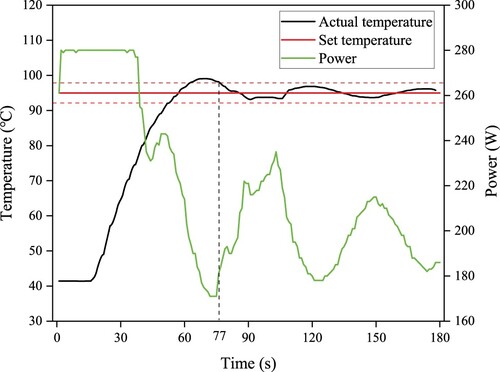
The epoxy ink was used to fabricate samples in a RWG microwave-assisted 3D printer. (a) schematically shows the main components in the printer while (b) shows the actual assembled setup. The operating frequency and maximum output power of the solid-state microwave generator are f = 2.45 GHz and 300 W, respectively. A general proportional–integral–derivative (PID) control system with temperature feedback from the infrared thermometer is adopted to adjust the microwave output power to achieve a stable ink temperature ranging from 45 to 200°C. shows the measured heating temperature and microwave output power when the temperature was set to 95°C. After 77 s, the actual temperature remained stable within ±3% of the target temperature. The inner diameter of the quartz tube is 4 mm, and this represents the dimension of the printing nozzle. The microwave-assisted 3D printing process was conducted at room temperature (25°C) and captured in a camera. After printing, the pre-cured samples were placed in an oven at 90°C for 1H to fully cure.
Figure 1. (a) Schematic of the RWG microwave-assisted 3D printer and (b) the actual assembled setup of the printer.
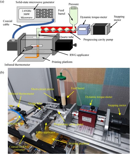
Figure 2. Measured temperature and microwave output power curves with the target temperature set to 95°C.
2.3. Characterisation
The viscosity of epoxy ink without curing agent was measured in an MCR 302 rheometer (Anton Paar, Austria) in the mode of controlled shear rate (0.1 s−1) within the temperature ranging from 25 to 105°C and a heating rate of 4°C/min. However, measurement of real-time rheological behaviour of the epoxy ink during the extrusion process under microwave radiation is a challenge. Microwave radiation causes variation in viscosity of the ink inside the tube, which increases the extrusion resistance. Therefore, another physical quantity, torque, was introduced to demonstrate the change in viscosity indirectly. As shown in (a), a dynamic torque-meter is installed between the stepping motor and the progressing cavity pump (PCP) to measure the torque during the ink extrusion within the temperature range from 50°C up to 105°C with a step of 5°C. The variation in torque represents an increase or decrease in the viscosity of the ink. The measured torque can be used to elucidate the effect of microwave radiation temperature on the fluid-gel state transition during 3D printing. The torque was measured when the microwave radiation temperature was stable, and three measurements were taken to obtain the average value at each temperature.
After microwave-assisted 3D printing, the extruded epoxy ink was quickly cooled in the refrigerator to stop the curing reaction. The reaction time with microwave radiation was estimated to be 9.8 s by dividing the waveguide radiation length (43.18 mm) with the flow velocity (4.4 mm/s). The rheological properties of the extruded epoxy ink samples were measured in the MCR 302 rheometer after the cooled ink returned to room temperature (25°C). A parallel plate-plate flow (a diameter of 60 mm and a gap of 1 mm) was used to measure the linear viscoelastic region (LVR), the storage modulus (G′) and loss modulus (G″) in the oscillatory mode at a frequency of 1 Hz under the applied shear stress from 0.1 to 1000 Pa. After the LVR was determined, the dynamical oscillatory frequency sweep tests were performed in the controlled strain mode. The angular frequency was decreased from 100 to 0.01 rad/s, and all measurements were taken at the strain value of 0.5% (within the LVR) to determine the variation of G′ and G″ with angular frequency.
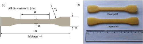
Tensile tests of dumbbell-shaped specimens ((a)) were performed in a universal testing machine Sans 3503. Two different types of specimens ((b)) were prepared by microwave-assisted 3D printing. The printing path direction of horizontal and longitudinal specimens is parallel and perpendicular to the tension direction, respectively. For comparison, casting specimens were prepared by silicone rubber moulds and then cured in a self-assembled multimode microwave heating cavity. Before tensile testing, the actual dimension of each specimen was measured with a calliper. During the tensile test, the specimen was loaded with a constant crosshead speed of 2 mm/min until it fractured. After testing, tensile strength and elastic modulus were extracted from the measured stress–strain curves. Three specimens were tested under the same conditions, and the average and standard deviation of tensile strength and elastic modulus were calculated.
Figure 3. (a) Geometric dimension of a tensile test specimen and (b) two different types of printed specimens for tensile testing.
2.4. Simulation of RWG applicator
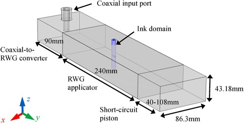
A multiphysics model of the RWG applicator was developed in the COMSOL Multiphysics software to simulate the electrical and magnetic fields and the heat transfer in the ink. shows the geometry of the model that includes a coaxial input port, a coaxial-to-RWG converter, an RWG applicator, a short-circuit piston and an ink domain. The transverse cross section of the RWG applicator is 86.3 mm wide and 43.18 mm high. The lengths of the converter and the RWG are 90 and 240 mm, respectively. The length of the short-circuit piston varies from 40 to 108 mm to find the optimal length. The distance of the coaxial input port from the converter boundary is 28.4 mm. The diameter of the ink domain is 4 mm. The velocity field of the ink is simplified to a uniform motion of −4.4 mm/s in the z-direction. The heat transfer in fluid and electromagnetic waves (frequency domain) analysis systems in the COMSOL software were used to perform this simulation. The governing equations of the physical fields are described below.
Figure 4. Geometrical model to simulate the rectangular waveguide (RWG) applicator.
Maxwell equations (EquationEq. (1)(1)
(1) ) were used to analyse the electric field distribution in the RWG microwave radiation system:
(1)
(1) where
is the electric field (V/m),
is the angular wave frequency (2πf, rad/s),
= 3 × 10⁸ m/s is the speed of light in vacuum,
= 0.92 is the relative permeability of the ink,
= 2.1 and
= 0.12 are the real and imaginary parts of the complex permittivity of the ink, respectively. The
,
and
of cured epoxy were directly measured using the transmission line coaxial method in an Agilent E5071C Keysight Vector Network Analyzer at the frequency of 2.45 GHz. The volumetric heat source through electric field and dielectric was calculated:
(2)
(2) where
is the electromagnetic heat generation term (W/m3),
is the electrical conductivity of the ink (S/m), and
= 8.854 × 10⁻¹² F/m is the free space permittivity. The heat transfer in the ink domain were determined by the following equation:
(3)
(3) where
= 1202 kg/m3 is the density of the ink,
= 4095 J/(kg·K) is the specific heat capacity at constant stress,
is the velocity vector (m/s),
= 0.577 W/(m·K) is the fluid thermal conductivity, and
is the absolute temperature (K). The following settings were applied: Coaxial for the type of input port and Dielectric loss for the electric displacement field. The initial temperature is 298.15 K. Electromagnetic heating elements were used to mesh the domain. The element size was Extra fine. The study was set as Sequential Frequency-Transient (frequencies = 2.45 GHz) with a time step of 0.5 s. Both the electric field norm and the magnetic field norm of the RWG domain were output. Both the electromagnetic power loss density and the temperature of the ink domain were also calculated.
3. Results and discussion
3.1. Determination of the critical structure parameters of the RWG applicator
This study proposed a microwave-assisted 3D printing head based on an RWG applicator ((b)). Ink can feed the quartz tube inside the RWG through the holes in the upper and lower walls. Curing reaction is induced by microwave radiation over a short part of the tube within the RWG. Two critical structure parameters of the RWG applicator were determined using the simulation: the length of the short-circuit piston and the ink extrusion position in the RWG applicator.
3.1.1. Determination of the short-circuit piston length
The length of short-circuit piston influences the reflection coefficient of the coaxial input port (S11) and the electromagnetic field distribution inside the RWG. S11 represents the proportion of energy reflected to the port and can be calculated from the ratio of reflection power (Pr) to input power (Pin) (EquationEq. (4)(4)
(4) ).
(4)
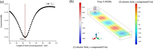
(4) A lower reflection coefficient (S11) suggests that better matching of the RWG applicator is achieved and more microwave energy is absorbed by the ink. The short-circuit piston length varied from 40 to 108 mm in the simulation. (a) shows the effect of the short-circuit piston length on the reflection coefficient. As the length of the short-circuit piston increases, the absolute value of S11 first increases and then decreases, reaching the peak at the length of 63 mm. With this length, the microwave energy reflected to the input port is minimised. Therefore, the optimal length of the short-circuit piston is determined to be 63 mm. (b) shows the electric field distribution inside the RWG applicator with the short-circuit piston length 63 mm. In the coaxial cable, the electric field is mainly radial, and the x component dominates. Standing waves are generated inside the RWG, and the sectional view shows that the electric field is dominated by the z component. The microwave is converted to the TE10 mode through the converter.
Figure 5. (a) Variation of S11 with the length of short-circuit piston and (b) electric field inside the RWG applicator with the short-circuit piston length 63 mm.
3.1.2. Determination of the ink extrusion position in the RWG applicator
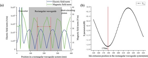
The ink extrusion position in the RWG applicator influences the heating uniformity of ink and the absorption efficiency of microwave. (a) shows the variation of the electric and magnetic fields along the centre line of the RWG applicator when the short-circuit piston length is 63 mm. Three groups of electric and magnetic field peaks occur in the RWG applicator with nearly the same peak values. The red line region indicated in (a) includes a group of electric and magnetic field peaks and is located in the middle of the RWG applicator, which is convenient for drilling holes to place the quartz tube. Therefore, the relationship between the ink extrusion position and S11 was investigated in this region ((b)). When the ink extrusion position is at 179 mm of the RWG applicator, the absolute value of S11 is the maximum of 1.68 dB. According to EquationEq. (4)(4)
(4) , this indicates the highest microwave energy absorption with an absorption rate of 32.08%. The maximum electric field occurs at this position (179 mm), which suggests that the epoxy ink used in this study is a dielectric loss material. The epoxy ink interacts with the strong electric field. The interaction generates induced currents and converts microwave energy into thermal energy. If the ink extrusion position is at 220 mm, where the magnetic field is the maximum, the ink exhibits the worst absorption of microwave energy, because the absolute value of S11 reaches the minimum absolute value of 0.06 dB, with an absorption rate of 1.37%, as shown in (b).
Figure 6. (a) Electric and magnetic field modes in the RWG applicator and (b) variation of S11 with the ink extrusion position in the RWG applicator.
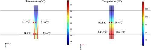
(a) shows the distribution of electromagnetic power loss density when the ink extrusion position (220 mm) is located at the maximum magnetic field. The electromagnetic power loss mainly concentrates on the tube wall, while there is minimal heating at the tube centre. During the microwave-assisted 3D printing process, if the temperature at the tube wall is too high, excessive curing tends to occur and leads to tube blockage. As shown in (b), when the ink extrusion position (179 mm) is located at the maximum electric field, the difference in electromagnetic power loss between the tube wall and centre is minimal. This precisely targeted heating of the ink facilitates stable temperature control and avoids microwave energy dissipation inside the cavity. shows the simulated temperature distribution of the ink inside the tube. When the ink extrusion position (179 mm) is located at the maximum electric field, the ink temperature increases rapidly due to the higher electromagnetic power loss density. The temperature is very similar along the entire length from the wall to the centre. The maximum temperature difference is 2.5°C at the RWG inlet. However, when the ink extrusion position (220 mm) is located at the maximum magnetic field, the electromagnetic power loss is lower, and the temperature rises slowly with the maximum temperature of only 38.4°C on the wall. The temperature difference along the entire length from the wall to the centre is significant with a maximum temperature difference of about 4.8°C. Therefore, the optimal extrusion location for epoxy ink is at the maximum electric field, where the temperature rises rapidly and distributes uniformly from the wall to the centre.
Figure 7. Electromagnetic power loss density of the ink when the ink extrusion position is located at: (a) the maximum magnetic field and (b) the maximum electric field.
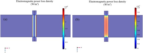
Figure 8. Simulation results of temperature distribution of the epoxy ink in the tube inside the RWG after microwave heating for 1 min when the ink extrusion position is located at the maximum magnetic field (left) and the maximum electric field (right).
The above analysis is only applicable to the pure epoxy ink used in this study. If the addition of other fillers leads to changes in the ink's dielectric properties, it is necessary to change the ink's position in the RWG. For example, if magnetic fillers such as carbonyl iron powder are added to the ink, the heating uniformity and efficiency will be better at the 220 mm position with the maximum magnetic field. Therefore, two waist-shape holes with a width of 10 mm were cut in the 160–230 mm section on the top and bottom walls of the RWG for the quartz tube to pass through ((a)). The section of 160–230 mm completely covers the position of the maximum electric and magnetic fields in order to achieve relatively uniform heating and curing for inks with different dielectric properties. In addition, to control temperature during the printing process, waist-shape holes with a width of 10 mm were cut at the same position on the front and rear walls of the RWG ((a)). In the experiments, an infrared thermometer was used to measure the internal temperature. A cover plate with a tube was added outside the waist-shaped hole of each wall to prevent microwave leakage, as shown in (b).
3.2. Microwave radiation temperature effect on extrusion behaviour
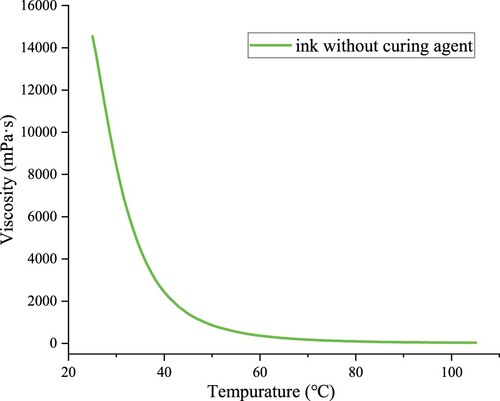
The temperature of epoxy ink increases under microwave radiation. The increase in temperature has both negative and positive effects on the printability of the ink. As shown in , the increase in temperature leads to a rapid decrease in viscosity of the epoxy ink, which causes deposited filaments to flow and spread. On the other hand, the increase in temperature induces the curing reaction of the epoxy ink with latent curing agents in 3D printing. When the reaction temperature and reaction time are reached, a network structure forms, which is beneficial for retaining the shape of printed structures [Citation12,Citation33–35]. Therefore, the process window of microwave radiation temperature is important to the printability of epoxy ink and was determined by the extrusion behaviour of ink.
Figure 9. Viscosity of epoxy ink without curing agent as a function of temperature.
shows the state of the extruded epoxy ink at different microwave radiation temperatures (T). The temperature has a significant impact on the apparent state of extruded inks. Five different states were observed at 13 temperatures in the experiment.
Figure 10. Images of the extruded epoxy ink at different microwave radiation temperatures. Red circles show the insufficiently cured liquid ink in single-layer epoxy ink samples deposited at 75°C.
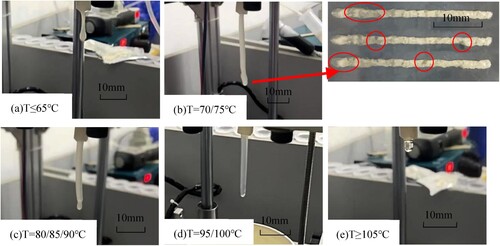
When T ≤ 65°C ((a)), the ink presents elongated droplets at the outlet of the tube. The ink has the same flow characteristic as the original ink cured without microwave assistance. It does not exhibit the shape retention ability.
From T = 70 to 75°C ((b)), the ink is extruded discontinuously in the form of a cylindrical state. The ink starts to have the shape retention ability. However, the extruded ink has the morphology of bamboo-like structures or even fractures. The deposited filaments contain insufficiently cured liquid ink, resulting in rough edges and non-uniform line width.
From T = 80 to 90°C ((c)), the ink initially presents a continuous cylindrical state. But after being extruded for about 10–15 mm, a long droplet occurs, and the ink's shape retention ability disappears.
From T = 95 to 100°C ((d)), the extruded ink exhibits a stable and continuous cylindrical state with a smooth and uniform surface morphology. A good shape retention of the extruded ink is achieved at this temperature range.
When T ≥ 105°C ((e)), the extruded ink exhibits lower viscosity, and small liquid droplets appear.
The effect of microwave assistance on the curing behaviour was investigated by measuring the torque changes during the extrusion of two types of inks (with and without curing agent addition) in the 3D printing, as shown in . The two curves of torque have decreasing trends from room temperature (25°C) to 60°C, which implies the decreased viscosity of the ink. At this temperature range, the microwave energy is insufficient to induce the curing reaction, and the epoxy resin maintains small monomers. It should be noted that the difference in torque between the two curves is due to the addition of 15% powdered curing agent.
Figure 11. Effect of microwave radiation temperature on the torque that represents the viscosity of extruded inks.
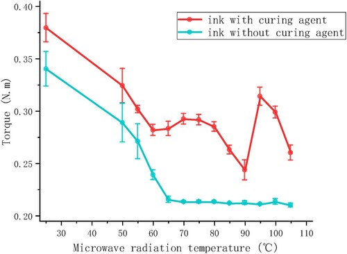
When the temperature exceeds 65°C, the torque of the ink without curing agent stabilises at 0.21 N·m (), which is required for ink transportation within the PCP. This indicates the low viscosity inside the tube and the negligible resistance. For the ink with curing agent, the required torque is notably different compared to the ink without curing agent. An increase in torque indicates the beginning of curing reaction. Between 70 and 80°C, the torque is almost stable (). It is analysed that the curing reaction is not intense enough to form a wholly macromolecule network structure between 70 and 80°C. Therefore, the extruded ink has surface defects.
As the temperature reaches 80–90°C, the torque of the ink with curing agent significantly decreases (). It is assumed that an intense curing reaction is accompanied by increased heat release, which results in the decreased viscosity.
At the temperatures of 95–100°C, the torque of the ink with curing agent significantly increases, reaching the peak at 95°C (). This indicates that the curing of the epoxy ink has reached the gel point at this temperature range. Consequently, the viscosity rapidly increases, and the macromolecule network structure becomes densified. This counteracts the viscosity-reduction due to increased temperature and results in a stable gelatinous state, which is suitable for printing.
When the temperature exceeds 105°C, the torque of the ink with curing agent again decreases significantly (). The curing reaction tends to stabilise, but the excessively high temperature causes the failure of the macromolecule network structure, leading to a lower viscosity.
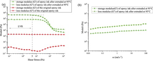
(a) shows the storage modulus (G′) and loss modulus (G″) of epoxy ink by microwave-assisted 3D printing. For comparison, the rheological properties of the original epoxy ink without microwave assistance were also measured. These measurements provide insight into the solid-like nature of the ink and reflect the ability of the ink to hold its shape after deposition [Citation36]. For the original epoxy ink, G″ is higher than G′ throughout the range of stresses, indicating that the epoxy ink exhibits the liquid-like behaviour. Therefore, the ink will spread and slump rapidly after extrusion and cannot be printed without microwave assistance. However, after the microwave-assisted 3D printing at 95°C, both the G′ and G″ of the ink increased, especially G′, by five orders of magnitude. The ink exhibits a shear yield stress of 120 Pa, below which the storage modulus is higher than the loss modulus. Based on the stress sweep test results, the corresponding stress value of the linear viscoelastic region (LVR) is 5 Pa for epoxy ink by microwave-assisted 3D printing. The LVR shows the range of shear stresses at which the ink structure is not altered. The frequency sweep test results in (b) show that the G′ and G″ values do not increase significantly throughout the entire frequency sweep range. The G′ is always higher than the G″ in the frequency range. This indicates high solid-like characteristics of the epoxy ink due to the strong colloidal structure, and a significant improvement in the shape retention and printability of the epoxy ink with microwave assistance.
Figure 12. Storage modulus (G′) and loss modulus (G″) of the epoxy ink after reaction for 9.8 s (a) in the stress sweep measurements from 0.1 to 1000 Pa and (b) in the frequency sweep measurements from 100 to 0.01 rad/s. For comparison, G′ and G″ of the original epoxy ink without microwave assistance are also shown.
Based on the above experiments, the processing window of microwave radiation temperature was determined to be 95°C ≤ T ≤ 100°C. To mitigate heating in the coaxial cable and RWG applicator, the microwave radiation temperature was controlled at 95°C during 3D printing in this study.
3.3. Microwave-assisted 3D printing performance
The microwave-assisted 3D printing performance was investigated by depositing a straight filament with a single pass length of 120 mm. The layer height was set to 2.6 mm. The quality of deposited filaments at different PCP rotary speeds is shown in (a). At the PCP rotary speed 40 rpm, the deposited filaments have a rough surface and uneven line width (widest 4.36 mm, narrowest 2.61 mm). At the PCP rotary speed within the range of 55–70 rpm, the filaments have a smooth surface texture and nearly uniform line width. The line width is 4.40 ± 0.04 and 5.23 ± 0.09 mm for the PCP rotary speed 55 and 70 rpm, respectively. When the PCP rotary speed increases to 85–100 rpm, an unstable macromolecule network structure forms in the extruded ink due to the shorter reaction time (microwave radiation time reduced by 2.3 and 3.6 s compared to 70 rpm, respectively), resulting in the spreading of the edges of the deposited filaments. The widest width reaches 8.72 and 8.99 mm, respectively. Therefore, a screw pump rotary speed of 70 rpm was chosen to maintain a stable line width while achieving high printing efficiency.
Figure 13. Quality of deposited filaments by microwave-assisted 3D printing at (a) different PCP rotary speeds and (b) different printing speeds.
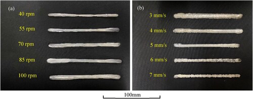
At the PCP rotary speed 70 rpm determined above, the effect of printing speed was investigated in the experiment. The quality of deposited filaments at different printing speeds is shown in (b). At the printing speed 3 mm/s, the platform moves relatively slowly. The extruded ink accumulates at the nozzle outlet and overflows to both sides, resulting in large and uneven line width (widest 8.71 mm, narrowest 7.16 mm). As the printing speed increases to 4 and 5 mm/s, the deposited filaments become continuous and uniform with the line width of 5.6 ± 0.07 and 5.04 ± 0.04 mm, respectively. When the printing speed increases to 6–7 mm/s, the extruded ink fails to be deposited entirely on the platform due to the fast motion of the platform, and instead the ink is dragged away, leading to rough or even fractured surface of the filaments. Based on the experiment, a printing speed of 5 mm/s was determined, as it offers high printing efficiency and a stable line width.
3.4. Printability of multiple layers
As demonstrated before, a single layer of epoxy ink can be printed with good quality using microwave-assisted 3D printing at a PCP rotary speed 70 rpm and printing speed 5 mm/s. However, the ink must also be able to support the weight of subsequent layers. Good printability of multiple layers is achieved if the solidified ink has sufficient strength and stiffness to resist yielding, buckling and excessive deformation under the weight of subsequent layers [Citation37]. To evaluate the layer support of epoxy ink with microwave assistance, a twelve-layer thin-walled sample with a single pass length of 160 mm was printed, and the layer height was set to 2.6 mm. The epoxy ink was deposited stably without spreading or layer slumping, as shown in (a). The filaments in each layer of the twelve-layer thin-walled sample sustained their initial shape throughout the length without gaps or voids, as shown in (b) and (c). The average width and average height of the twelve-layer thin-walled sample were 4.96 ± 0.11 and 31.15 ± 0.39 mm, respectively. So the aspect ratio of 6.28 is high. summarises and compares the aspect ratio of layer support samples achieved in the typical DIW processes and the microwave-assisted 3D printing in this work. With microwave radiation, the epoxy ink, which was initially neither printable nor stackable, reached the layer-supporting ability that other DIW processes have achieved. This research demonstrates the effectiveness of microwave radiation in improving the shape retention and printability of epoxy ink.
Figure 14. (a) Printing process of layer support and (b and c) large and small thin-walled samples printed by 4 mm and 1.5 mm nozzle, respectively.
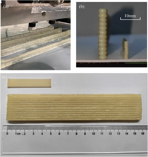
Table 1. Comparison of sample aspect ratio between the typical DIW processes and the microwave-assisted 3D printing in this study.
Microwave-assisted 3D printing of finer filaments was also attempted using a 1.5 mm nozzle (inner diameter of the quartz tube is 1.5 mm). A ten-layer thin-walled sample with a single pass length of 50 mm was successfully printed at a PCP rotary speed 37 rpm, printing speed 10 mm/s and microwave radiation temperature 95°C, as shown in (b) and (c). The layer height was set to 1 mm. The average width and average height of the ten-layer thin-walled sample were 1.91 ± 0.02 and 9.94 ± 0.04 mm, respectively. The aspect ratio is 5.20. The flatness of the lateral surface is significantly improved compared to the thin-walled sample printed with 4 mm diameter nozzle. Microwave-assisted 3D printing of fine filaments could provide an external surface finish with high resolution. Thick filament printing could achieve a larger printing scale, and it is possible to accelerate the time-consuming process of internal filling.
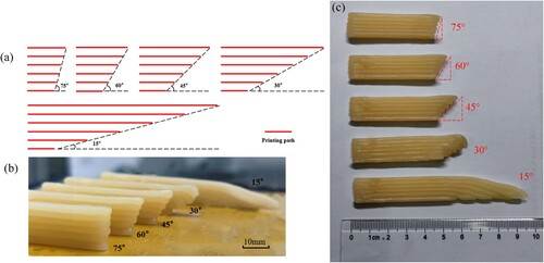
Six-layer single path suspended structures with different slope angles 15°, 30°, 45°, 60°, and 75° were designed to investigate the shape retention ability of extruded ink, as shown in (a). The samples were printed using a 4 mm nozzle and the layer height was set to 2.6 mm. The suspended parts at 75°, 60°, and 45° retained the shape and did not show any bending deformation. For the angles 30° or 15°, the parts cannot retain the long suspended lines, resulting in bending and collapse, as shown in (b) and (c). The maximum extension of each printed layer reached 2.6 mm at 45°. This indicates that the extruded epoxy ink can print limited-span structures.
Figure 15. (a) Schematic of printing path of the six-layer single path suspended structures with different slope angles; (b and c) printed suspended structures with different angles.
3.5. Mechanical properties
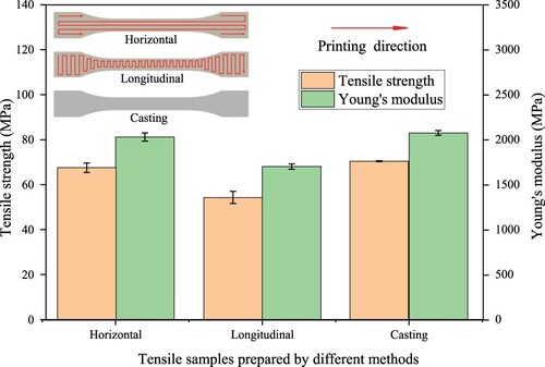
shows the tensile strength and Young's modulus of three types of specimens prepared by different methods: horizontal printed specimens, longitudinal printed specimens and casting specimens. The tensile strength (67.67 MPa) and Young's modulus (2029.26 MPa) of the horizontal specimens prepared by microwave-assisted 3D printing are higher than those of the longitudinal specimens (54.49 and 1701.89 MPa, respectively). The tensile properties of microwave-assisted 3D printing epoxy parts exhibit anisotropic effects. In addition, the tensile strength (70.57 MPa) and Young's modulus (2075.12 MPa) of the casting specimens were slightly higher than those of the horizontal specimens. This indicates that the microwave-assisted pre-curing process did not significantly reduce the mechanical properties of the epoxy ink.
Figure 16. The tensile strength and Young's modulus of dumbbell-shaped specimens prepared by 3D printing and casting.
4. Conclusion
In this work, a microwave-assisted 3D printer using the rectangular waveguide (RWG) was developed for epoxy resin. The printability and shape retention of epoxy ink were improved and verified through printing tests. The following conclusions can be obtained:
The critical parameters of the RWG applicator used in the developed microwave-assisted 3D printer were determined by the multiphysics simulation. The RWG applicator achieves optimal microwave system matching when the short-circuit piston length is 63 mm. The maximum microwave absorption and the uniform heating of epoxy ink appear when the ink extrusion position is located at 179 mm in the RWG applicator with maximum electric field.
In microwave-assisted 3D printing, the rheological behaviour of epoxy ink is highly sensitive to microwave radiation temperature. The microwave-induced curing reaction is beneficial to increase the viscosity of the ink, but higher temperature can decrease the viscosity. When the microwave radiation temperature is in the range of 95–100°C, the storage modulus of the extruded ink is significantly increased by five orders of magnitude, and the extruded ink exhibits a continuous and stable cylindrical morphology with a smooth and uniform surface. In this temperature range, the curing of epoxy ink reaches the gel point, and the macromolecule network structure becomes densified, achieving the ideal state of the extruded ink for 3D printing.
The feasibility of microwave-assisted 3D printing of epoxy ink is confirmed by the experimental results. Filaments of good quality can be deposited with stable line width at the microwave radiation temperature 95°C, the PCP rotary speed 70 rpm and the printing speed 5 mm/s. A high aspect ratio of 6.28 was achieved in the twelve-layer thin-walled sample. In addition, the tensile strength and Young's modulus of the epoxy specimens prepared by microwave-assisted 3D printing, especially printed along the tensile direction, were close to the mechanical properties of the cast specimens.
This study demonstrates that microwave-assisted 3D printing based on RWG is applicable for DIW of epoxy ink with the desirable shape retention and printability. This work can be applied to the DIW of microwave absorption structures with more precise geometric details in the future, such as the wood-pile structures [Citation43].
Disclosure statement
No potential conflict of interest was reported by the author(s).
Data availability statement
The authors confirm that the data supporting the findings of this study are available within the article.
Additional information
Funding
References
- Pascault J, Williams RJJ. Thermosetting polymers, in Handbook of Polymer Synthesis, Characterization, and Processing, 2013; pp. 519–533. doi: 10.1002/9781118480793.ch28
- Arun ND, et al. Nonplanar 3D printing of epoxy using freeform reversible embedding. Adv Mater Technol. 2023;8(7):2201542. doi: 10.1002/admt.202201542
- Lewis JA, Gratson GM. Direct writing in three dimensions. Mater Today. 2004;7(7–8):32–39. doi:10.1016/S1369-7021(04)00344-X
- Chi H, et al. Three-dimensional printing and recycling of multifunctional composite material based on commercial epoxy resin and graphene nanoplatelet. ACS Appl Mater Interfaces. 2022;14(11):13758–13767. doi: 10.1021/acsami.2c00910
- Marnot A, et al. Material extrusion additive manufacturing of high particle loaded suspensions: a review of materials, processes and challenges. Virtual Phys Prototyp. 2023;18(1):e2279149. doi: 10.1080/17452759.2023.2279149
- Zhao G, et al. Ti/β-tcp composite porous scaffolds fabricated by direct ink writing. Virtual Phys Prototyp. 2023;18(1):e2192703. doi: 10.1080/17452759.2023.2192703
- Kuang X, et al. High-speed 3D printing of high-performance thermosetting polymers via two-stage curing. Macromol Rapid Commun 2018;39(7):1700809. doi: 10.1002/marc.201700809
- Barki AM, Bocquet L, Stevenson A. Linking rheology and printability for dense and strong ceramics by direct ink writing. Sci Rep 2017;7(1):6017. doi: 10.1038/s41598-017-06115-0
- Weng Y, et al. Printability and fire performance of a developed 3D printable fibre reinforced cementitious composites under elevated temperatures. Virtual Phys Prototyp. 2019;14(3):284–292. doi: 10.1080/17452759.2018.1555046
- Zhong J, et al. 3D printing strong and conductive geo-polymer nanocomposite structures modified by graphene oxide. Carbon. 2017;117:421–426. doi: 10.1016/j.carbon.2017.02.102
- Compton BG, Lewis JA. 3D-printing of lightweight cellular composites. Adv Mater 2014;26(34):5930–5935. doi: 10.1002/adma.201401804
- Chen KJ, et al. Fabrication of tough epoxy with shape memory effects by UV-assisted direct-ink write printing. Soft Matter. 2018;14(10):1879–1886. doi: 10.1039/C7SM02362F
- Griffini G, et al. 3D-printable CFR polymer composites with dual-cure sequential IPNs. Polymer. 2016;91:174–179. doi: 10.1016/j.polymer.2016.03.048
- Zhu J, et al. 3D printing of multi-scalable structures via high penetration near-infrared photopolymerization. Nat Commun 2020;11(1):3462. doi: 10.1038/s41467-020-17251-z
- Sun Y, et al. 3D printing of thermosets with diverse rheological and functional applicabilities. Nat Commun 2023;14(1):245. doi: 10.1038/s41467-023-35929-y
- Liao H. Stereolithography using compositions containing ceramic powders. Canada: University of Toronto; 1997.
- Endruweit A, Johnson MS, Long AC. Curing of composite components by ultraviolet radiation: a review. Polym Compos 2006;27(2):119–128. doi: 10.1002/pc.20166
- Huang L, et al. Synthesis and optimization of a free-radical/cationic hybrid photosensitive UV curable resin using polyurethane acrylate and graphene oxide. Polymers (Basel). 2022;14(10):1959. doi: 10.3390/polym14101959
- Wang TB, Liu J. A review of microwave curing of polymeric materials. J Electron Manuf 2000;10(3):181–189. doi: 10.1142/S0960313100000162
- Mgbemena CO, et al. Accelerated microwave curing of fibre-reinforced thermoset polymer composites for structural applications: a review of scientific challenges.. Compos Part A Appl Sci Manuf 2018;115:88–103. doi: 10.1016/j.compositesa.2018.09.012
- Naik TP, Singh I, Sharma AK. Processing of polymer matrix composites using microwave energy: a review. Compos Part A Appl Sci Manuf 2022;156:106870. doi: 10.1016/j.compositesa.2022.106870
- Odom MGB, et al. Rapid curing and additive manufacturing of thermoset systems using scanning microwave heating of carbon nanotube/epoxy composites. Carbon. 2017;120:447–453. doi: 10.1016/j.carbon.2017.05.063
- Thostenson ET, Chou TW. Microwave processing: fundamentals and applications. Compos Part A Appl Sci Manuf 1999;30(9):1055–1071. doi: 10.1016/S1359-835X(99)00020-2
- Clark DE, Sutton WH. Microwave processing of materials. Annu Rev Mater Sci 1996;26:299–331. doi: 10.1146/annurev.ms.26.080196.001503
- Li K, et al. Quantitative evaluation of the non-thermal effect in microwave induced polymer curing. RSC Adv 2021;11(6):3740–3750. doi: 10.1039/D0RA08427A
- Bolasodun B. Microwave effects on the curing, structure properties and decomposition of epoxy resins. United Kingdom: University of Manchester; 2011.
- Shimamoto D, Tominaga Y, Hotta Y. Effect of microwave irradiation on carbon fiber/epoxy resin composite fabricated by vacuum assisted resin transfer molding. Adv Compos Mater 2016;25(sup1):71–79. doi:10.1080/09243046.2016.1178998
- Román Manso B, et al. Embedded 3D printing of architected ceramics via microwave-activated polymerization. Adv Mater 2023;35(15):2209270. doi: 10.1002/adma.202209270
- Li N, Link G, Jelonnek J. Rapid 3D microwave printing of continuous carbon fiber reinforced plastics. CIRP Ann. 2020;69(1):221–224. doi: 10.1016/j.cirp.2020.04.057
- Li N, et al. Microwave additive manufacturing of continuous carbon fibers reinforced thermoplastic composites: characterization, analysis, and properties. Addit Manuf. 2021;44:102035. doi: 10.1016/j.addma.2021.102035
- Zhao Z, et al. Synergistic effect of microwave 3D print and transglutaminase on the self-gelation of surimi during printing. Innov Food Sci Emerg Technol. 2021;67:102546. doi: 10.1016/j.ifset.2020.102546
- Yu X, et al. Effects of preheating-induced denaturation treatments on the printability and instant curing property of soy protein during microwave 3D printing. Food Chem 2022;397:133682. doi: 10.1016/j.foodchem.2022.133682
- Zhou Z, et al. An imidazolium-based supramolecular gelator enhancing interlayer adhesion in 3D printed dual network hydrogels. Mater Des 2021;206:109792. doi: 10.1016/j.matdes.2021.109792
- Deng K, Zhang C, Fu KK. Additive manufacturing of continuously reinforced thermally curable thermoset composites with rapid interlayer curing. Compos Pt B-Eng. 2023;257:110671. doi: 10.1016/j.compositesb.2023.110671
- Guan D, et al. Rheological study on the cure kinetics of two-component addition cured silicone rubber. Chin J Polym Sci 2016;34(10):1290–1300. doi: 10.1007/s10118-016-1847-8
- Compton BG, et al. Electrical and mechanical properties of 3D-printed graphene-reinforced epoxy. JOM. 2018;70(3):292–297. doi: 10.1007/s11837-017-2707-x
- Rau DA, Williams CB, Bortner MJ. Rheology and printability: a survey of critical relationships for direct ink write materials design. Prog Mater Sci 2023;140:101188. doi: 10.1016/j.pmatsci.2023.101188
- Romberg SK, et al. Linking thermoset ink rheology to the stability of 3D-printed structures. Addit Manuf. 2021;37:101621. doi: 10.1016/j.addma.2020.101621
- Costakis WJ, et al. Additive manufacturing of boron carbide via continuous filament direct ink writing of aqueous ceramic suspensions. J Eur Ceram Soc 2016;36(14):3249–3256. doi: 10.1016/j.jeurceramsoc.2016.06.002
- Rau DA, et al. A dual-cure approach for the ultraviolet-assisted material extrusion of highly loaded opaque suspensions. Addit Manuf. 2023;72:103616. doi: 10.1016/j.addma.2023.103616
- Kam D, et al. 3D printing of cellulose nanocrystal-loaded hydrogels through rapid fixation by photopolymerization. Langmuir. 2021;37(21):6451–6458. doi: 10.1021/acs.langmuir.1c00553
- Kopatz JW, et al. Compositional effects on cure kinetics, mechanical properties and printability of dual-cure epoxy/acrylate resins for DIW additive manufacturing. Addit Manuf. 2021;46:102159. doi: 10.1016/j.addma.2021.102159
- Zhang Z, et al. Ultra-broadband and wide-angle metamaterial absorber with carbon black/carbonyl iron composites fabricated by direct-ink-write 3D printing. Adv Eng Mater 2023;25(6):2201236. doi: 10.1002/adem.202201236