
 ?Mathematical formulae have been encoded as MathML and are displayed in this HTML version using MathJax in order to improve their display. Uncheck the box to turn MathJax off. This feature requires Javascript. Click on a formula to zoom.
ABSTRACT
The AlCoCrFeNi2.1 eutectic high-entropy alloys (EHEAs) were prepared using selective laser melting (SLM) to study the tribological properties at high temperatures, focusing on the complex mechanism of the friction process. The density of the SLM EHEAs is 99.70%. The lamellar and cellular structures are unevenly distributed at different locations. In situ XRD demonstrated the transition from BCC to FCC with increasing temperature. A large number of B2 particles are distributed in the BCC matrix. The fluctuation of the friction coefficient is closely related to the shape and size of the wear debris. The hardness of the alloy is ∼105 HV at 1000 °C. The wear rate first increases and then decreases with increasing temperature. The maximum thickness of the oxide film is 13.52 μm at 1000 °C and exhibits delamination. The combination of mechanical, materials and physicochemical effects during friction contributes to the excellent high temperature wear resistance.
1. Introduction
Eutectic high-entropy alloys (EHEAs) is a typical in-situ composite material with layer or rod-like eutectic structure, which combines the advantages of both eutectic alloys and high-entropy alloys [Citation1–3]. High-strength phases (e.g. Body-centered cubic (BCC) or hexagonal close-packed (HCP)) and high-plasticity phases (e.g. Face-centered cubic (FCC) phases) are eutectic grown to form EHEAs. Therefore, EHEAs can balance strength and ductility with superior overall performance compared with the traditional single-phase FCC or single-phase BCC HEAs [Citation4, Citation5]. The main contribution to the realisation of the combination of high strength and plasticity in the as-cast AlCoCrFeNi2.1 EHEAs comes from the combination of the two-level confinement effect and the self-generated microcracking inhibition of the fracture mechanism, with ultimate tensile strengths (UTS) of more than 1.1 GPa and ductility approaching 20% [Citation6], which results in a broad potential for applications.
Presently, high-entropy alloys and most metal parts still rely on traditional casting, forging and pressing methods of production, which will not only cause coarse structure and elemental segregation, further affecting the mechanical properties, but also lead to waste of material resources due to the later cutting process. However, components such as engine blades, turbine disks, and combustion chambers in aerospace, as well as liner plates, crushing hammerheads, crawler plates, and other wear-resistant parts under complex operating conditions place higher performance requirements and more resource-saving economic demands on materials that serve in extreme environments. Additive Manufacturing (AM) is the ideal solution to address these limitations.
AM is a process based on the 3D printing process of layer by layer processing, local melting, and rapid solidification, which is superior to traditional manufacturing methods in terms of manufacturing flexibility and reducing material waste [Citation7, Citation8]. Selective laser melting (SLM), an advanced additive manufacturing process, allows for the personalisation of metal parts that cannot be manufactured by traditional techniques such as casting, forging and rolling. Meanwhile, the rapid cooling rates (103-108K/s) characteristics of SLM inhibit grain growth and elemental segregation, promote the formation of supersaturated solid solutions and dispersed fine phases, giving the products excellent mechanical properties [Citation9, Citation10]. Wang et al. [Citation9] demonstrated that the hardness of SLM AlCoCrCuFeNi high-entropy alloy is as high as about 700 HV, which is much higher than that of cast alloy (500 HV) [Citation11], which is attributed to the inevitable high-density dislocation stacking and entanglement due to the fast solidification rate of SLM. Guo et al. [Citation12] used a mixture of AlCoCrFeNi pre-alloyed powder and high-purity Ni powder as the raw powder and successfully applied the SLM technique to prepare AlCoCrFeNi2.1 EHEAs with a maximum ultimate tensile strength (UTS) of 1480 MPa, which is significantly higher than that of 1100 MPa in the as-cast state [Citation13]. Tang et al. [Citation14] used AlCoCrFeNi2.1 pre-alloyed powder prepared by gas atomisation as raw material, and the UTS and yield strength (YS) of the SLM products were 1518 ± 12.5 MPa and 1235 ± 34.5 MPa, which were nearly 54% and 130% higher than those of the vacuum induction melting samples, respectively. Our previous work has measured the YS of SLM AlCoCrFeNi2.1 EHEAs up to 1071 MPa with an elongation of 11% [Citation15]. The heat-treated sample can maintain UTS = 1065 MPa while the elongation is increased to 21.97% [Citation4]. These excellent mechanical properties provide the alloy with a wide range of service environments.
In the service life of metallic materials, wear is one of the important factors leading to the failure of mechanical equipment and components [Citation16]. The large-scale equipment and aerospace components inevitably cause frictional wear at high temperature and extreme environments, and the requirement of wear resistance is an important evaluation index for their continued serviceability. Friction wear is a complex interfacial contact process, the mutual movement of the friction pair can cause alloy weight loss, chemical reactions, phase transitions, and even electrical properties of the complex interfacial system [Citation17, Citation18]. The higher hardness (650 HV) of the SLM AlCoCrFeNi2.1 EHEAs may also confer superior wear resistance [Citation2]. Xi et al. [Citation19] investigated the wear resistance of WC reinforced AlCoCrFeNi2.1 EHEAs prepared by SLM. The results showed that the increase in systematic wear resistance was due to interfacial load transfer strengthening of WC particles and solid solution strengthening of W and C atoms. Miao et al. [Citation20] also confirmed that EHEAs exhibits superior hardness, softening resistance and tribological properties over a wide temperature range. However, the protective effect and high-temperature frictional oxidation behaviour provided by the complex friction chemistry of SLM AlCoCrFeNi2.1EHEA during high-temperature friction on its self are not clear.
In this work, AlCoCrFeNi2.1 EHEAs were prepared by SLM technology, and the highest densities of molded products were obtained by tuning the SLM parameters to study their physical phase composition and microstructure. The complex mechanical, materials, and physicochemical effects of the alloys at high temperatures were analyzed through wear experiments and wear product detection, and the tribological behaviour and friction mechanism of SLM AlCoCrFeNi2.1 EHEAs were investigated.
2. Materials and methods
2.1. SLM processing
The sample was prepared by Hans-M100 SLM machine, equipped with a 500 W fibre laser. The working principle of SLM is shown in (a), and the schematic diagram of the scanning method of the SLM forming process is shown in (b). The scanning strategy of a single laser beam was abandoned during the preparation process, and a laser strip containing multiple laser beams with a width of 10 mm was used as the heat source. The diameter of the internal laser beam spot was 50 μm, and the lap width of the adjacent laser strip was 70 μm. This method significantly improves manufacturing efficiency compared to scanning with a single laser beam as the heat source. A scanning method with the same layer in the same direction and neighbouring layers rotated by 67° is used to build layer by layer, which not only improves the work efficiency but also reduces the thermal stress concentration. The optimised SLM printing parameters were selected as listed in . The AlCoCrFeNi2.1 EHEAs powder with the particle size range of 15-53μm produced by gas atomisation method was used as raw material. The good sphericity of the alloy powder is displayed in (c), the embedded text shows the powder particle size distribution. The internal microstructure of the powder is a typical eutectic lamellar structure, which is attributed to the melting of the metal raw material and the rapid solidification of the powder particles.
Figure 1. (a) SLM working principle; (b) The schematic diagram of the scanning method of the SLM forming process; (c) Powder morphology and particle size distribution; (d) Internal microstructure of the powder.
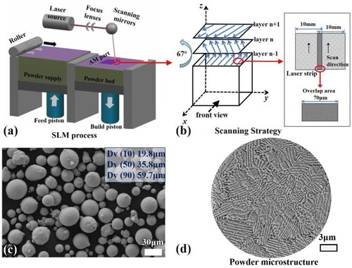
Table 1. SLM processing parameters for preparing the EHEAs samples.
2.2. High temperature friction and wear test
High temperature wear sample size is 20 × 10 × 8 mm3. High temperature friction and wear testing machine (MPT-3G, manufactured by Jinan Hengxu testing machine Technology Co., LTD, China) was used to perform wear tests at different temperatures (20°C, 200°C, 400°C, 600°C, 800°C, 1000°C). The temperature was recorded, employing the cromel-alumel thermocouples with the accuracy of ±1.5 percent. The friction pair is the hard Si3N4 ball (∼1500 HV) with a diameter of 5.5 mm. Under the normal load of 10 N (the average contact stress is about 1.086 GPa), the friction track diameter is set at 8 mm, the sliding speed is 200 r/min (0.084 m/s), and the test cycle time is 3600 s. The coefficient of friction was recorded during cyclic friction using a load cell. A three-dimensional (3D) surface profiler based on scanning white light interferometry extracted the morphology of the wear tracks, and the volume loss of the alloy was calculated by measuring the depth and width of the wear scars. The volume loss is defined as [Citation16]:
(1)
(1) where
is the volumetric loss, L is the perimeter of the wear ring, h and b are the depth and width of the wear scars respectively.
2.3. Characterise
Optical microscopy (OM, OLYMPUS, BX53M) is used to observe the internal morphology and porosity of polished SLM printed specimens. X-ray computed tomography (XCT, Seamaster PRO-DT) technology was used to measure the relative density (RD) of SLM samples. High-temperature wear specimens are SLM specimens gradually heated to the required temperature, to identify more accurately the type and content of phases during wear tests, in-situ X-ray diffractometer (XRD, Bruker D8, Advance) with Co Kα radiation is used for the inspection. The scanning range was from 20° to 105° in 2θ at a scanning rate of 4°/min, the heating rate was 10°C/min. The macroscopic morphology, microstructure of the samples and morphology of the wear scar surface and wear debris were observed with a scanning electron microscope (SEM, Gemini 300). The texture information, grain boundaries, and kernel-averaged orientation error (KAM) were analyzed by electron back-scatter diffraction (EBSD, Oxford C-swift) (step size of measurement is 0.2 μm). Boundary angles less than 15° are characterised as low-angle grain boundaries (LAGB), and those greater than 15° are characterised as high-angle grain boundaries (HAGB). The morphology of samples thinned by a dual jet polishing machine with a mixture of 30% nitric acid and 70% methanol at – 12°C and 15 V was observed under the transmission electron microscope (TEM, JEOL 2010). TEM examination samples were selected from SLM printed original specimens. The X-ray photoelectron spectroscopy analysis (XPS, ESCALAB250) was employed to determine the chemical compounds of the worn surface tested at 1000°C. The high temperature hardness was tested by HL-X7 high temperature Vickers hardness tester with diamond indenter. The heating rate is 20°C/min, which is close to the heating rate of high-temperature friction test process. Holding for 5 min after reaching the target temperature, and the high temperature hardness test is carried out at room temperature, 200°C, 400°C, 600°C, 800°C and 1000°C respectively. Holding at 1000 g load for 15s. The wear rate is defined as follows [Citation21]:
(2)
(2) where Wr is the wear rate,
is the volumetric loss of the specimen after sliding, S is the sliding distance, and P is the load.
3. Results
3.1. SLM forming sample
The macroscopic morphology of the SLM sample is shown in (a). There are a large number of fine unmelted (or incompletely melted) alloy powders on the surface parallel to the building direction, reflecting a large roughness. This can be attributed to the larger mobility and dynamic viscosity of the melt after absorbing the laser energy and during solidification, which can drag the powder at the front end of the edge melt pool into the melt pool [Citation22]. While the surface perpendicular to the building direction exhibits smoother laser melting channels. Meanwhile, the strong transient non-equilibrium interaction between the high-energy laser beam and the powder particles inevitably resulted in the internal pores, as shown in (b).
Figure 2. (a) SEM image of the macroscopic morphology of the SLM printed sample.; (b) OM image of internal morphology and defects of samples; (c) Micro-CT detection spectrum of SLM sample.
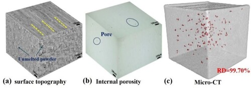
The relative density (RD) of the sample is 99.70% (as shown in (c), with red markers indicating the location and morphology of the internal pore defects), which is close to the full density, as detected by XCT. This was used as an original sample for friction wear.
3.2. Phase analysis and microstructure
The XRD pattern (a) shows that the SLM AlCoCrFeNi2.1 EHEAs are composed of FCC and BCC(B2) phases, which is in agreement with previous studies [Citation1, Citation13]. The localised magnification of XRD at 42.75°−45° shows that the FCC (111) and BCC(B2) (110) diffraction peaks of the SLM EHEAs are shifted to lower diffraction angles with increasing temperature, suggesting that similar lattice distortions are occurring in the two phases. The lattice parameters of the FCC and BCC (B2) phases of the samples at different temperatures were calculated according to the Rietveld refinement method, as shown in (d). As the temperature increases, the lattice parameter of the BCC (B2) phase increases, while the lattice parameter of the FCC phase exhibits complex changes. In this alloy system, the atomic radius of Al is the largest, and the change of lattice parameters may be related to the content of Al element in the matrix phase. During the heating process, the secondary phase precipitates in the BCC matrix, causing changes in the lattice parameter, which has been confirmed by previous studies [Citation23]. During the heating process, the release and generation of macroscopic residual stresses are inevitably induced, which causes anisotropic lattice contraction and lattice distortion, leading to a slight shift in the position of the XRD peaks [Citation24].
Figure 3. (a) In-situ XRD patterns of SLM AlCoCrFeNi2.1 EHEAs at different temperature, (b) XRD local magnification pattern at 42.75°−45.5°, (c) Relative phase content calculated from XRD and (d) lattice parameters of the FCC and BCC(B2) phases
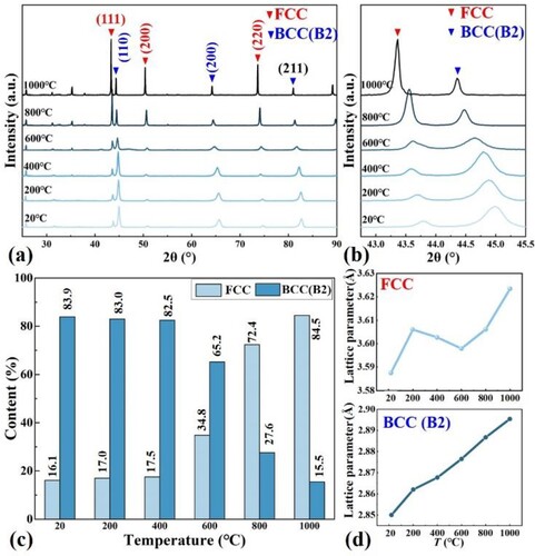
The phase content distribution of the alloy at room temperature is 16.1% FCC and 83.9% BCC(B2). Compared with single laser beam scanning and melting methods, the 10 mm wide laser heat source can reduce the number of scanning cycles. The fast solidification rate and reduced heat reinput result in different phase distribution results from other studies [Citation25, Citation26]. The relative content of the phase changes with increasing temperature, and the FCC content is 84.5% at 1000°C, while the BCC (B2) content is 15.5%. This confirms the transition of BCC(B2) phase to FCC phase. This is attributed to the fact that the Gibbs free energy () of the FCC phase is lower at relatively higher temperatures and is relatively stable compared to BCC(B2) [Citation9]. As the temperature increases, the fluctuation and diffusion of component concentrations intensify, promoting the combination of elemental Al with more Ni. The Ni3Al phase (one kind of FCC phase) is easier to crystallize and nucleate than NiAl (one kind of BCC(B2) phase) in the same temperature interval, leading to an increase in the content of the FCC phase [Citation19].
The inverse pole figure (IPF) (a) and pole figure (PF) (b) of SLM samples analyzed by EBSD detection observed epitaxially grown columnar crystal orientations parallel to the melt pool temperature gradient and perpendicular to the melt pool boundary. The non-uniform nucleation region at the melt pool boundary provides a substrate for subsequent metal solidification, and the major axis perpendicular to the melt pool boundary is the direction with faster growth rate for priority growth, whereas the other directions inhibit the lateral growth of crystals due to the lack of a unique heat transfer direction [Citation27]. However, the cross-growth of column crystals is hindered by the rotation of the scanning direction between layers, resulting in the column crystal growth orientation being altered by the laser scanning of the next layer [Citation28].
Figure 4. EBSD analysis of SLM AlCoCrFeNi2.1 EHEAs. (a) inverse pole figure (IPF) colouring maps; (b) pole figure (PF) maps; (c) grain boundaries (GBs) map; (d) kernel average misorientation (KAM) map.
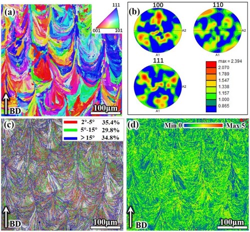
As can be seen in (c), 65.2% of LAGBs (marked by red and green lines) are mostly distributed inside the melt pool, and 35.8% of HAGBs are mainly distributed at the melt pool boundary (marked by blue lines). The length of LAGBs is associated with high residual stress and dislocation density. It is well known that the unique thermal history of SLM usually leads to high thermal stress accumulation in as-built samples, which further contributes to the high dislocation density in the microstructure [Citation29]. Subsequent thermal cycling of SLM may promote dislocation movement and rearrangement, but it is not sufficient to eliminate the dislocations or the dislocation cell structure transitioning to high-angle grain boundaries, and thus a large number of low-angle grain boundaries are retained [Citation30]. Short-term remelting and high-temperature heat transfer classes at the melt pool boundary can be considered as annealing, leading to recrystallization, resulting in the gradual transformation of previously formed LAGBs into HAGBs. The high residual stress accumulation in the SLM specimens is reflected in the KAM profile (from blue to red colour indicates the change of KAM value from small to large, which also indicates the change of residual stress from small to large).
shows the microstructure of the melt pool at different locations parallel to the building direction. Different temperature gradients (G) and solidification rates (R) at different locations of the melt pool lead to the diversity and complexity of microstructures. From the bottom to the top of the melt pool, the solidification rate decreases gradually. As shown in (b), the two types of eutectic layer structures are noted near the melt pool boundary. The average eutectic layer spacing inside the melt pool close to the melt pool boundary line is only 171.5 ± 25 nm (Type 1), which is much lower than that of the layer spacing of the cast AlCoCrFeNi2.1 EHEAs (∼2 μm) [Citation31]. This is the reason for the grain refinement caused by the high solidification rate. The eutectic lamellar structure near the melt pool boundary becomes wider (Type 2), which is due to the reheating remelting of the solidified areas. This process is equivalent to a short period of high temperature heat treatment, the grains grow by engulfing each other, leading to the widening of the lamellar structure of about 350 nm. The columnar structures in the direction of the thermal gradient can be observed inside the melt pool ((c)). In the upper part of the melt pool, the temperature gradient decreases and supercooling induces the formation of isometric crystals with cellular structure ((d)).
Figure 5. Microstructure at different locations (a) Melt pool morphology; (b) at the boundary of the melt pool; (c) inside the melt pool; and (d) top of the melt pool; (e) STEM bright-field (BF) images; (f)TEM image of the dashed rectangle marked area in (e);(g) inverse fast Fourier transform (IFFT) of the B2 particles. (h) SAED patterns of the FCC (h1), BCC (h2) phases, (i) elemental distribution.
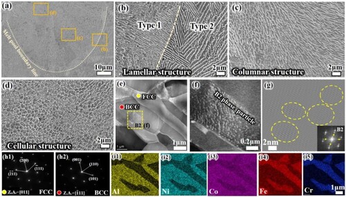
(e) shows the TEM bright-field (BF) images of SLM AlCoCrFeNi2.1 EHEA lamellar structure. According to the selected area electron diffraction (SAED) (Figure h1, h2), it can be determined that the regions marked in red and yellow are BCC and FCC phases, respectively. As shown in (f), a large number of particles in the BCC matrix are B2-phase particles (locally enlarged in e), the nano-scale B2 particle precipitated within the grains identified by inverse fast Fourier transform (IFFT), as shown in (g). In addition, it is consistent with previous reports that the BCC phase is rich in Al and Ni, while the FCC phase has more Cr and Fe, as reflected in (i1)-(i5).
3.3. Mechanical properties and wear performance
3.3.1. Hardness
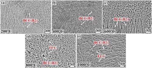
demonstrates the microstructure morphology of the alloy after wear experiments. The bright areas are FCC phase and the dark areas are BCC (B2) phase. For 200 and 400 °C, the area fraction of the dark areas is much larger than that of the bright areas, and the grain size is smaller, which is close to the structure morphology of SLM EHEAs (). The FCC areas gradually increase with increasing temperature. This is the same as the change in phase content as tested by XRD.
Figure 6. Microstructure of the alloy after high temperature wear testing (a) 200°C, (b) 400°C, (c) 600°C, (d) 800°C, (e)1000°C.
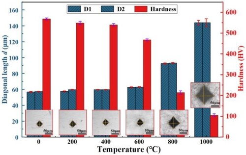
The diagonal lengths of Vickers hardness indentations and calculated hardness values of SLM print specimens at different temperatures are shown in . Below 400°C, the microstructure within this temperature range does not change dramatically, the hardness decreases slowly as the temperature increases, from 568.8HV at 20 °C to 540.3HV at 400 °C. In the later heating stage, the hardness drops seriously, from 468.3HV at 600°C to 105HV at 1000°C. The main reasons are (i) the high temperature softening effect, (ii) the transition of hard BCC to soft FCC phase promoted by high temperature, (iii) incomplete densification of SLM pattern leads to oxygen infiltration along pore and crack defects, leading to the destruction of the internal structure and impairment of the properties [Citation32].
Figure 7. The diagonal length of indentation (D1, D2) and Vickers hardness values at different temperatures
3.3.2. Friction coefficient
The coefficient of friction (COF) is one of the most fundamental properties of material contact mechanics and is one of the main factors affecting the shear strength of particulate materials. The relative motion of the friction pair leads to a temperature rise and a transformation of the surface properties of the material, which affects the COF. An increase in environmental temperature causes a phase transition in the metal and changes the crystal structure, which in turn affects the COF [Citation33].
(a1)-(f1) show the COF at different temperatures and the corresponding collected wear debris ((a2)-(f2)). The results reflected that the magnitude of COF fluctuation is related to the wear debris size. In addition, frictional heat leads to oxidation of the friction surface. The fluctuation of the COF curve is caused by changes in the sliding surface interface during friction, such as removal of material defects, plastic deformation of the substrate, disruption and re-formation of the oxide layer, as well as accumulation and removal of debris from the friction surface [Citation34]. The periodic cyclic loading acting on the wear surface promotes shear plastic deformation and accumulation of the surface metal, and the maximum shear deformation occurs at a certain depth within the surface layer [Citation35]. As friction proceeds, cracks and holes form at the maximum shear deformation. The normal stress in the plane promotes crack extension in the direction of the plane until the material between the crack and the surface flakes off in the form of flake fragments [Citation18]. From (a2) – (c2), the size of the flake-like wear debris gradually increases, and these debris are inevitably retained on the surface of the wear scar, increasing the surface roughness and leading to an increase in the magnitude of fluctuations in the COF, as reflected in (a1)-(c1). During sliding friction, the coefficient of friction at the sliding interface increases with the inclusion of large amounts of wear debris, leading to increased friction. Generally, the smoother the contact surface, the smaller the COF, the gradual increase of COF from 20°C-400°C in the stable stage proves this conclusion. At lower temperatures, the EHEAs is a complex morphology microstructure dominated by BCC (B2) phase, and under repeated cyclic shear stress, the wear surface and subsurface are easily produced by stress concentration. The flake-like wear debris is more easily flake off from the hard matrix with uncoordinated deformation and enter the wear track, which increases the COF fluctuation.
Figure 8. Friction coefficient (COF) acquisition and wear debris morphology: (a1)(a2) 20°C; (b1)(b2) 200°C; (c1)(c2) 400 °C; (d1)(d2) 600 °C; (e1)(e2) 800 °C; (f1)(f2) 1000 °C. The average COF for the stabilisation phase has been marked in the figure.
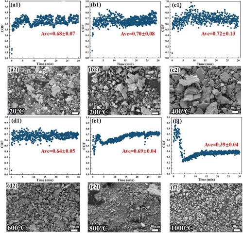
Between 600°C-800°C, the size of the flake-like debris decreases with increasing temperature and gradually transforms into particle debris. In this high-temperature stage, the FCC phase content increases, the grain size increases, the matrix ductility increases, and the wear debris is easily crushed by the cyclic load and then enters the wear track, reducing the COF fluctuation. However, it is worth noting that the debris in (e2) is a complex mixture of fragments and particles, so the increase in COF at 800 °C may be due to more severe friction between the complex mixed debris as the third body and the rough surface, as reflected in (e1).
The friction debris at 1000°C has been transformed into particles, and the fine particles are not enough to cause the sensor to vibrate violently, which is reflected in the slight fluctuation of the coefficient of friction, as shown in (f2). Most of these micron-sized particles are circular, which means that many balls are added between the friction pairs. The presence of balls transforms sliding friction into rolling friction on a microscopic scale, reducing COF, as depicted in (f1).
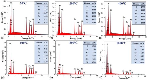
The chemical composition of the debris is examined using EDS, as summarised in for the relative elemental content, and it is found that the debris gradually suffered from severe oxidation as the temperature increased, especially after 400°C, when the oxidation rate increased dramatically. During subsequent friction, these oxidised particles continue to participate in the relative motion, compacting them under cyclic loading. This repeated plastic deformation leads to work-hardening of the material and the formation of an oxide layer with a homogeneous composition on the wear surface, which will be described in detail below.
Figure 9. The EDS analysis of the highlighted wear debris in at.%. (a) 20°C; (b) 200°C; (c) 400 °C; (d) 600 °C; (e) 800 °C; (f) 1000 °C
3.3.3. Worn surface and wear mechanism
shows the wear scar surfaces of SLM HEAs at different temperatures. From 20°C-600°C, the grooves parallel to the sliding direction and a large amount of particle debris are typical features of abrasive wear. In particular, in (b) and (c), the abrasive scratched grooves are deeper and wider, which is consistent with the results of higher COF caused by large-sized debris in (b)(c), indicating the occurrence of more severe abrasive wear. Meanwhile, the heavily oxidised flaked debris as reflected by can be determined as the abrasive wear of oxidised particles. In addition, loose particles and areas of plastic deformation on the wear surface reveal the characteristics of adhesive wear. Fine powdery wear debris, mainly caused by micro-cutting of hard abrasives, can be taken as clear evidence of abrasive wear [Citation36].
Figure 10. Wear morphologies of SLM EHEAs at different temperatures: (a1)(a2) 20 °C; (b1) (b2) 200 °C; (c1) (c2) 400 °C; (d1) (d2) 600 °C; (e1) (e2) 800 °C; (f1) (f2) 1000 °C
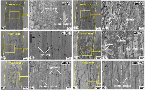
At room temperature, due to the absence of high-temperature softening effect, the surface hardness of the material is higher and the elastic deformation of the friction-pair contact is smaller, which leads to a smaller contact area and an increase in the contact pressure of the friction pair. It is easier to form bonding points at the contact interface, and the characteristics of adhesive wear are more prominent [Citation37], so adhesive wear is most serious at room temperature. The decrease in the area of dark areas and the number of particles with increasing temperature indicates a decrease in the degree of adhesive wear.
The distribution of elements on the wear surface at different temperatures is listed in , during frictional wear, the O content gradually increases with increasing temperature. The O concentration on the wear surface reaches to increase from 4.73 at.% at 20°C to 60.45 at.% at 1000°C, which indicates the generation of oxidised wear.
Table 2. Distribution of elements on the surface of wear scar at different temperatures (at.%).
A severe delamination fracture is detected in (e), which is caused by brittle fracture of the oxide layer. Friction is an energy-consuming process. In addition to frictional heat, the formation of wear debris is also a manifestation of energy consumption [Citation38]. Fracture of brittle materials is caused by normal stress. The hard and brittle oxide film is destroyed cyclically, and when the accumulated energy exceeds a critical value, flakes are produced or even peeled off, thus forming a layered structure and leading to delamination wear. The surface morphology is smoother as the temperature increases to 1000°C ((f)), and the high-temperature softened debris is compacted and coated on the wear surface, reflecting the characteristic of delamination wear.
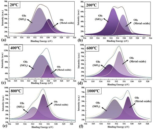
The XPS of elemental O within the wear surface of EHEAs at 20–1000 °C is shown in . Based on the fitting analysis of the assay results, there are two structural forms of elemental O, metal oxide and SiO2. The presence of the SiO2 peak is due to the transfer of Si3N4 to the surface of the material and friction chemistry during severe dry friction [Citation17]. The peak intensity of metal oxides increases with increasing temperature, and conversely, the peak of SiO2 gradually decreases, which also indicates that the higher the temperature, the more severe the oxidation. In the process of transferring hard SiO2 to the friction part, the surface of the material is inevitably scratched, aggravating the wear of the wear mark surface. Wear debris adhering to the SiO2 surface further grinds the material surface, causing grooves, which is one of the reasons why the abrasive wear mechanism arises. The formation of the oxide film prevents the transfer of SiO2, further reducing its damage to the surface of the abrasive scars, and to a certain extent reduces the effect of abrasive wear.
Figure 11. XPS of oxygen element on the wear surface at different temperatures.
3.3.4. Wear rate
Wear rate is an important indicator for evaluating the wear resistance of materials. The classical Archard's law [Citation32] assumes that the wear resistance of a material is directly proportional to its hardness, however, the experimental results here do not apply, as illustrated in and , which can be attributed to the complex mechanical, materials and physicochemical effects of the wear surface on the high-temperature frictional.
Figure 12. Wear rate of EHEAs at different temperatures.
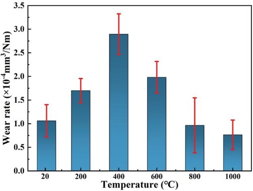
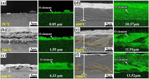
The wear rate first increases and then decreases with increasing temperature, with a turnaround at 400°C. The oxide film thickness of the cross-section of the wear track is detected as shown in . At room temperature, the thickness of the oxide film on the wear surface is only 0.85 μm, and with the increase of temperature, and the growth rate of the oxide film slows down as the temperature increases, eventually reaching a thickness of about 13.52 μm at 1000°C. Under the action of cyclic loading, the oxide fragments are compacted into the wear surface, which is conducive to the thickening of the oxide layer. However, at present, the density of the oxide layer is not enough, the removal of the oxide film flaking rate is greater than the generation rate, the wear rate gradually increases. In addition, the O increment may lead to the brittleness of the material surface, called oxygen embrittlement [Citation39]. Due to Al and Cr in EHEAs are strong oxide forming elements, O absorption is higher and oxygen embrittlement is stronger [Citation40]. As a result, microcracks and localised brittle fractures (as shown in ) tend to form on thinner oxide films with increasing contact stresses, causing to a certain degree higher COF and wear rates.
Figure 13. SEM and EDS mapping of the oxide layers in the cross-sections of the wear tracks of EHEAs at different temperatures: (a) 20°C; (b) 200 °C; (c) 400 °C; (d) 600 °C; (e) 800 °C; (f) 1000 °C. The average thickness values of oxide film are marked in the figures.
The temperature is increased to above 600°C, and the agglomerated particles remaining on the friction surface are subjected to more significant thermoelastic stress and compaction during cyclic friction. At the same time, the debris is more easily sintered together, and the sintering rate of the particles increases with increasing temperature. The rate of oxidation of the residual metal in the particles increases, and the oxide fragments destroyed by high temperature and high pressure are formed again and recompacted onto the smooth surface to form stronger and smoother solid layers [Citation18, Citation41], which provide long-lasting protection and reduce the wear rate. Further, as the friction partner is being exposed to the atmosphere, the oxygen adsorption layer is always present on the surface of the alloy [Citation42]. During dry sliding friction, plastic deformation of the wear scar surface accelerates the diffusion of oxygen into the metal, favouring the thickening of the oxide film.
Thus, the compacted debris particles and the oxide layer formed by the diffusion of high temperature oxygen coexist on the sliding surface, and the higher coverage, thicker and denser oxide layer produced at high temperatures can better protect the material surface and reduce the wear rate [Citation43].
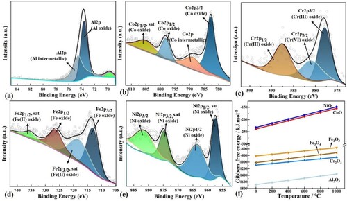
In order to determine the material composition of the oxide layer, the chemical states of Al, Co, Ni, Fe, and Cr in the wear track were determined by fitting and separating the XPS results into different oxidation states (). The XPS spectra indicates that the metal elements on the wear surface are predominantly in the form of oxides, but with different chemical bonding states, suggesting the production of multiple types of metal oxides. The XPS spectral fitting of Fe 2p detected Fe3+ (2p3/2 at 719.3 eV and 2p1/2 at 735.8 eV) and Fe2+ (2p3/2 at 713.5 eV and 2p1/2 at 726.5 eV), this means that doped Fe is comprised of a mixed valence of Fe2+/Fe3+.
Figure 14. XPS analysis of the worn surface of SLM EHEAs at 1000°C: (a) Al element; (b) Co element; (c) Cr element; (d) Fe element; (e) Ni element; (f) The Gibbers free energy of various simple oxides at different temperatures
Combining the Richardson-Ellington diagram [Citation44] and the work of other scholars [Citation45, Citation46], the possible oxidation reactions and corresponding Gibbs free energy (ΔGΘ, kJ·mol−1) of each solute element are as follows (thermochemical equation(3)-(8)), the ΔGΘ of the individual simple oxides as a function of temperature is shown in (f).
(3)
(3)
(4)
(4)
(5)
(5)
(6)
(6)
(7)
(7)
(8)
(8)
According to the relatively negative standard ΔGΘ in the relevant metal oxides, Al2O3, Cr2O3 would form in large numbers firstly during the sliding process. At different temperatures, dense Al2O3 and Cr2O3 were first formed on the surface of the wear scar. Based on the elemental distribution on the surface of the abrasion marks and the XPS peak intensity of SiO2, it can be predicted that the main components of the oxide film on the surface of the wear scar at 20°C are FeO, SiO2, and the oxides of Al and Cr. As the temperature increases, the SiO2 content gradually decreases, the oxides of Fe are gradually transformed into Fe2O3. It was previously reported that Fe3O4 has no satellite peaks [Citation47], and based on the lower ΔGΘ of Fe3O4, it can be hypothesised that a large amount of Fe3O4 is produced during the higher temperature friction process. In addition, it has been shown that some oxides are only produced above specific temperatures, for example, Co is oxidised to CoO when heated above 300 °C [Citation48].
The variation of x-values in NixAl affects the composition and content of the FCC and BCC(B2) phases. Qu et al. [Citation49] studied the micro-dynamic oxidation behaviour of Ni-Al alloys using ReaxFF molecular dynamics. According to the conclusions of the studies and the thermochemical reaction equations (3,7), O atoms tend to form Al-containing oxides at the positions of Al atoms on the alloy surface. Al atoms tend to detach from the alloy surface, leading to a variety of structural defects associated with the type of Al-containing, including atomic ring defects, tetrahedral distortions, and coordination defects. These defects become active sites for oxidation, which leads mainly to the formation of oxide nuclei near Al atoms and rarely to the formation of Ni-bearing oxides. At low temperatures, new oxides accumulate near the Al-containing oxides. For SLM AlCoCrFeNi2.1 EHEAs, the Al element is more inclined to be enriched in the BCC phase as shown in , so the oxidation rate is considered to be higher for BCC(B2) than FCC at lower temperatures. In addition, the poorer plasticity BCC phase at lower temperatures is more easily to produce microcracks under the cyclic loading of the friction process, which promotes the internal diffusion of O atoms and accelerates the oxidation rate.
Alloy oxidation is extremely sensitive to temperature. During the rapid oxidation phase, oxygen interacts with the surface, creating more active sites and leading to a rapid increase in the rate of oxidation. Atoms are more reactive at higher temperatures, which weakens atomic bonds, promotes the formation of cracks in the oxide film, releases oxygen into the interior of the alloy, and leads to the creation of new oxides. O atomic vibrations continue to increase with temperature, while Ni and Co atoms participate in the oxidation reaction at high temperatures [Citation50]. Moreover, Moreover, High temperature accelerates the diffusion of O atoms into the interior [Citation51]. As a result, the oxidation rates of both FCC and BCC phases are significantly increased at high temperatures, which is conducive to the formation of thicker oxide films.
As shown in , for all sliding cases, the raised oxide layer on the surface of the wear scar mostly shows a ruptured island-like distribution, while no friction cracks were identified to be produced in the alloy matrix at the bottom. Similarly, no microcracking features were detected in the alloy matrix under the oxide film in , which is attributed to the intrinsic eutectic microstructure of AlCoCrFENi2.1 EHEAs. Gao et al. [Citation13] using HRTEM have demonstrated that the eutectic phase interface in AlCoCrFeNi2.1 EHEA is semi-eutectic, which confers it with superior strength-ductility combination. The ductile FCC phase inhibits brittle fracture from cyclic loading, while the hard BCC (B2) phase leads to improved wear resistance of the EHEAs.
4. Discussion
4.1. Structure and growth behaviour of high temperature wear oxide film
Alloys in the high temperature oxidation process, the oxide film products to meet the thermodynamic formation conditions simultaneously, the environment and the oxide film/gas interface must exist at a certain oxygen partial pressure so that the reaction can occur. Oxygen partial pressure is also an important criterion for whether the solute elements can be oxidised. The partial pressure of oxygen required for the reaction to reach equilibrium is shown in formula (9) [Citation52].
(9)
(9) where a is the chemical potential of the alloying group element,
is the partial pressure of oxygen when the reaction reaches equilibrium,
is the standard ΔGΘ of the oxidation reaction, R is the Boltzmann constant, and T is the absolute temperature. Assuming that the chemical potential
of each reaction alloying element is equal to the corresponding atomic percentage of the alloying element, and the chemical potential
of the corresponding oxide of the solute element is approximately equal to 1, the standard ΔGΘ of each reaction at different temperatures can be obtained from EquationEq. (3)
(3)
(3) -(8).
After calculation, the Al element has better binding energy to O than other solute elements (Ni, Cr, Fe, Co), and Al reacts preferentially with O to form Al2O3. On the other hand, the lower the partial pressure of oxygen, the fewer solute elements are allowed to participate in the oxidation reaction of the alloy [Citation52].
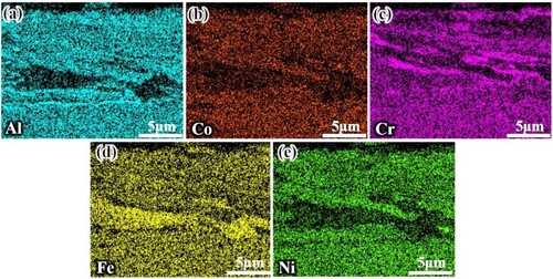
During wear, cyclic loading exposes fresh metal surfaces to high temperatures, and alloying elements undergo high-temperature oxidation. Due to the non-uniform distribution of oxygen partial pressure and elements at different locations and times on the surface of the wear scar, while the generated oxide film undergoes plastic deformation and removal/compaction effects under normal and tangential pressures, which contributes to the delamination of the oxide film, as reflected in .
Figure 15. EDS mapping of elemental distribution in the oxide film at 1000°C wear trace cross-section (a) Al; (b) Co; (c) Cr; (d) Fe; (e) Ni.
It is generally accepted that the formation of complex oxides tends to be generated by solid-state phase transitions of simple oxides. As the oxidation time proceeds, when two simple oxides are formed simultaneously and in adjacent positions after satisfying the thermodynamic formation conditions, the oxidation process is possible. For example, friction will further promote the reaction between NiO and Al2O3 to form NiAl2O4. Thermochemical Equations (10)-(13) summarise some of the complex metal oxidation reactions and the corresponding ΔGΘ, which also correspond to the multiple valence forms of the elements present in the XPS detection of wear scar [Citation52–54]. As the temperature increases to 600-1000°C, the SLM AlCoCrFeNi2.1EHEAs exhibit increasingly superior wear resistance, which is mainly due to the synergistic effect of the intrinsic eutectic microstructure and the formation of dense bimetallic oxide layers. During wear tests above 600°C, the single oxides further react with each other under force-heat coupling to form dense Ni-Cr, Co-Cr, Al-Co, and Ni-Al bimetallic oxide layers. As the temperature increases, the oxide layer gradually thickens, and the complex oxides and simple oxides form a more protective glaze layer, reducing the wear rate. The different physicochemical parameters and high-temperature softening effects of various oxidation products lead to differences in the distribution of oxides, which further accelerates the results of oxide film delamination.
(10)
(10)
(11)
(11)
(12)
(12)
(13)
(13)
4.2. Synergistic effect of mechanical, materials, and physical–chemical effects on high-temperature friction process
The friction process can change the kinetics of the chemical reaction between the friction parts, reducing the activation energy required for the reaction. Meanwhile, friction can initiate some chemical reactions at lower temperatures that require higher temperatures. This reaction caused by frictional energy is called friction chemical reaction, and the wear controlled by this reaction is called friction chemical wear [Citation17, Citation55]. The synergy of mechanical, materials and physicochemical effects of the friction process can effectively accelerate the surface modification of the friction interface. summarises the complex mechanisms involved in the friction process.
Figure 16. Schematic representation of mechanical, materials, and physicochemical effects on high-temperature friction behaviour.
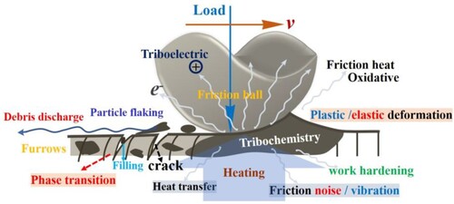
Frictional heat is a fundamental property of the friction process. When the surfaces of two bodies slide against each other, metal atoms and oxide molecules are constantly touching, hitting, and moving, and this thermal movement is transferred to other locations. In addition, the molecules between the friction pairs may be deformed, causing vibrations and distortions of the molecules, which leads to energy transfer and loss. The increased thermal motion of molecules, energy transfer, and loss all lead to an increase in material temperature [Citation56].
During wear tests at higher temperatures, different simple oxides further react with each other under thermal-force coupling to form a dense bimetallic oxide layer, such as preferentially generated CoCr2O4 and NiCr2O4, which undergoes a solid-state phase transition [Citation57]. The crystal structure of the bimetallic oxides contains many stacked defects, which lead to plastic deformation during wear tests and act as a lubricating phase to further improve the high-temperature wear resistance.
Microscopic irregular vibrations of friction contact surfaces are one of the fundamental reasons for friction noise. At the microscopic level, many bumps and depressions are caused by tiny wear debris on the friction track surface (reflected in and 10). When the three-body friction between the friction pair squeezes or slides against each other, the irregularities of the bumps and depressions cause subtle stress and displacement changes, resulting in friction noise, which is also one of the forms of energy dissipation [Citation58].
Surface physical–chemical refers to the physicochemical effects of chemical bonding and chemical combination on the surface of the materials, which can be changed with the friction on the surface of the materials, thus leading to friction damage [Citation56]. For example, at lower temperatures, the oxide film on thin surfaces is easily damaged (the thickness of the oxide film on wear surfaces at 20-400°C is less than 5μm), leading to increased oxidation reactions and thus accelerated corrosion and damage to the metal.
When the friction pair slides against each other, the binding capacity of the atomic nuclei of different objects to the electrons outside the nucleus is different, thus resulting in the loss and transfer of electrons.
5. Conclusion
In this work, AlCoCrFeNi2.1 EHEAs were prepared using selective laser melting. The microstructure of the SLM EHEAs, as well as the effect of temperature on the coefficient of friction, wear rate, and friction mechanism for different specimens were investigated, and finally, the complex effects of the friction process were summarised. The following conclusions were drawn:
The maximum density of the SLM EHEAs was 99.70%, which was close to fully dense.
The lamellar and cellular structures are unevenly distributed at different locations within the melt pool, and the grain size changes. In situ XRD demonstrated that the SLM alloy consists of FCC and BCC duplex phases. As the temperature increases, BCC transforms to FCC.
The hardness of the alloy decreases slowly until 400 °C and then rapidly. At 1000°C, the hardness of the alloy can be maintained at about 105 HV. The size and amount of debris on the surface of the wear scar leads to an overall trend of increasing and then decreasing friction coefficient. The wear rate increases and then decreases with increasing temperature, which is attributed to the weighting and thickening of the oxide film.
The oxide film thickness increased with increasing temperature, and the maximum thickness of the oxide film was 13.52 μm at 1000 °C, and it showed the phenomenon of delamination, which was caused by the partial pressure of oxygen and the thermodynamic factors of oxide generation. The surface of the wear scar consists of a combination of simple and complex metal oxides. The combination of mechanical, materials and physicochemical effects during friction contributes to the excellent high temperature wear resistance of the alloy.
Data availability statement
The raw/processed data required to reproduce these findings cannot be shared at this time as the data also forms part of an ongoing study.
Disclosure statement
No potential conflict of interest was reported by the author(s).
Additional information
Funding
References
- Lu Y, Gao X, Jiang L, et al. Directly cast bulk eutectic and near-eutectic high entropy alloys with balanced strength and ductility in a wide temperature range. Acta Mater. 2017;124:143–150. doi:10.1016/j.actamat.2016.11.016
- Lan L, Wang W, Cui Z, et al. Anisotropy study of the microstructure and properties of AlCoCrFeNi2.1 eutectic high entropy alloy additively manufactured by selective laser melting. J Mater Sci Technol. 2022;129:228–239. doi:10.1016/j.jmst.2022.04.020
- Yeh JW, Chen SK, Lin SJ, et al. Nanostructured high-entropy alloys with multiple principal elements: novel alloy design concepts and outcomes. Adv Eng Mater. 2004;6(5):299–303. doi:10.1002/adem.200300567
- Lan L, Zhang H, Yang Z, et al. Significant transitions of microstructure and mechanical properties in laser additive manufacturing AlCoCrFeNi2.1 eutectic high-entropy alloy under heat treatment. J Mater Res Technol. 2023;25:6250–6262. doi:10.1016/j.jmrt.2023.07.077
- Jiang L, Lu Y, Wu W, et al. Microstructure and mechanical properties of a CoFeNi2V0.5Nb0.75 eutectic high entropy alloy in As-cast and heat-treated conditions. J Mater Sci Technol. 2016;32(3):245–250. doi:10.1016/j.jmst.2015.08.006
- Shi P, Ren W, Zheng T, et al. Double-slit photoelectron interference in strong-field ionization of the neon dimer. Nat Commun. 2019;10(1):1–8. doi:10.1038/s41467-018-07882-8
- Zhang J, Song B, Wei Q, et al. A review of selective laser melting of aluminum alloys: processing, microstructure, property and developing trends. J Mater Sci Technol. 2019;35(2):270–284. doi:10.1016/j.jmst.2018.09.004
- Herzog D, Seyda V, Wycisk E, et al. Additive manufacturing of metals. Acta Mater. 2016;117:371–392. doi:10.1016/j.actamat.2016.07.019
- Wang Y, Li R, Niu P, et al. Microstructures and properties of equimolar AlCoCrCuFeNi high-entropy alloy additively manufactured by selective laser melting. Intermetallics. 2020;120:106746, doi:10.1016/j.intermet.2020.106746
- Guo M, Gu D, Xi L, et al. Formation of scanning tracks during selective laser melting (SLM) of pure tungsten powder: Morphology, geometric features and forming mechanisms. Int J Refract Met Hard Mater. 2019;79:37–46. doi:10.1016/j.ijrmhm.2018.11.003
- Singh S, Wanderka N, Murty B, et al. Decomposition in multi-component AlCoCrCuFeNi high-entropy alloy. Acta Mater. 2011;59(1):182–190. doi:10.1016/j.actamat.2010.09.023
- Guo Y, Su H, Zhou H, et al. Unique strength-ductility balance of AlCoCrFeNi2.1 eutectic high entropy alloy with ultra-fine duplex microstructure prepared by selective laser melting. J Mater Sci Technol. 2022;111:298–306. doi:10.1016/j.jmst.2021.10.013
- Gao X, Lu Y, Zhang B, et al. Microstructural origins of high strength and high ductility in an AlCoCrFeNi2.1 eutectic high-entropy alloy. Acta Mater. 2017;141:59–66. doi:10.1016/j.actamat.2017.07.041
- Tang X, Zhang H, Zhu Z, et al. Dual-phase synergistic deformation characteristics and strengthening mechanism of AlCoCrFeNi2.1 eutectic high entropy alloy fabricated by laser powder bed fusion. J Mater Sci Technol. 2023;150:75–85. doi:10.1016/j.jmst.2022.11.045
- Lan L, Wang W, Cui Z, et al. Unique duplex microstructure and porosity effect on mechanical properties of AlCoCrFeNi2.1 eutectic high-entropy alloys processed by selective laser melting. Acta Metallurgica Sinica (English Letters). 2023;36(9):1465–1481. doi:10.1007/s40195-023-01551-6
- Wang Y, Yang Y, Yang H, et al. Microstructure and wear properties of nitrided AlCoCrFeNi high-entropy alloy. Mater Chem Phys. 2018;210:233–239. doi:10.1016/j.matchemphys.2017.05.029
- Fischer TE, Anderson MP, Jahanmir S, et al. Friction and wear of tough and brittle zirconia in nitrogen, air, water, hexadecane and hexadecane containing stearic acid. Wear. 1988;124(2):133–148. doi:10.1016/0043-1648(88)90240-2
- Stott F. High-temperature sliding wear of metals. Tribol Int. 2002;35(8):489–495. doi:10.1016/S0301-679X(02)00041-5
- Xi S, Chen H, Zhou J, et al. Microstructure evolution and wear resistance of a novel ceramic particle-reinforced high-entropy alloy prepared by laser powder bed fusion. Ceram Int. 2024;50(4):5962–5973. doi:10.1016/j.ceramint.2023.11.162
- Miao J, Liang H, Zhang A, et al. Tribological behavior of an AlCoCrFeNi2.1 eutectic high entropy alloy sliding against different counterfaces. Tribol Int. 2021;153:106599, doi:10.1016/j.triboint.2020.106599
- Lan L, Wang X, Guo R, et al. Effect of environments and normal loads on tribological properties of nitrided Ni45(FeCoCr)40(AlTi)15 high-entropy alloys. J Mater Sci Technol. 2020;42:85–96. doi:10.1016/j.jmst.2019.08.051
- Meng G, Gua D, Xia L, et al. Formation of scanning tracks during Selective Laser Melting (SLM) of pure tungsten powder: Morphology, geometric features and forming mechanisms. Int J Refract Met Hard Mater. 2018;79.
- Guo Y, Su H, Yang P, et al. New insight into tailorable eutectic high entropy alloys with remarkable strength–ductility synergy and ample shaping freedom fabricated using laser powder bed fusion. Additive Manufacturing. 2022;60:103257, doi:10.1016/j.addma.2022.103257
- Niu S, Kou H, Guo T, et al. Strengthening of nanoprecipitations in an annealed Al0.5CoCrFeNi high entropy alloy. Mater Sci Eng A. 2016;671:82–86. doi:10.1016/j.msea.2016.06.040
- He L, Wu S, Dong A, et al. Selective laser melting of dense and crack-free AlCoCrFeNi2.1 eutectic high entropy alloy: Synergizing strength and ductility. J Mater Sci Technol. 2022;117:133–145. doi:10.1016/j.jmst.2021.11.049
- Lu Y, Dong Y, Guo S, et al. A promising new class of high-temperature alloys: eutectic high-entropy alloys. Sci Rep. 2014;4(1):6200, doi:10.1038/srep06200
- Li R, Shi Y, Liu J, et al. Effects of processing parameters on the temperature field of selective laser melting metal powder. Powder Metall Met Ceram. 2009;48(3-4):186–195. doi:10.1007/s11106-009-9113-z
- Bhardwaj T, Shukla M. Effect of laser scanning strategies on texture, physical and mechanical properties of laser sintered maraging steel. Mater Sci Eng. 2018;734(SEP.12):102–109. doi:10.1016/j.msea.2018.07.089
- Blackford B, Zak G, Kim IY. The effect of scan path on thermal gradient during selective laser melting. Int J Adv. Manuf Technol. 2020;110:1261–1274. doi:10.1007/s00170-020-05899-2
- Humphreys FJ, Hatherly M. Recrystallization and related annealing phenomena. Kidlington, Oxford, UK: Elsevier; 2012.
- Lu Y, Dong Y, Guo S, et al. A promising new class of high-temperature alloys: eutectic high-entropy alloys. Sci Rep. 2014;4(1):1–5.
- Bardal E. Corrosion and protection. Springer-Verlag London Limited; 2004.
- Guo P, Su X. Shear strength, interparticle locking, and dilatancy of granular materials. Can Geotech J. 2007;44(5):579–591. doi:10.1139/t07-010
- Nguyen C, Tieu AK, Deng G, et al. Tribological performance of a cost-effective CrFeNiAl0.3Ti0.3 high entropy alloy based self-lubricating composite in a wide temperature range. Tribol Int. 2022;174:107743, doi:10.1016/j.triboint.2022.107743
- Savkoor A, Briggs G. The effect of tangential force on the contact of elastic solids in adhesion. Proc R Soc London, Ser A Math Phys Sci. 1977;356(1684):103–114.
- Aung NN, Zhou W, Lim LE. Wear behaviour of AZ91D alloy at low sliding speeds. Wear. 2008;265(5-6):780–786. doi:10.1016/j.wear.2008.01.012
- Hou J, Zhang M, Yang H, et al. Surface strengthening in Al0.25CoCrFeNi high-entropy alloy by boronizing. Mater Lett. 2019;238:258–260. doi:10.1016/j.matlet.2018.12.029
- Yang R, Guo X, Yang H, et al. Tribological behavior of boronized Fe40Mn20Cr20Ni20 high-entropy alloys in high temperature. Surf Coat Technol. 2023;464:129572, doi:10.1016/j.surfcoat.2023.129572
- Woodford D, Bricknell R. Environmental embrittlement of high temperature alloys by oxygen. Treatise Mater Sci Technol. 1983;25:157–199. doi:10.1016/B978-0-12-341825-8.50011-8
- Stoloff NS, Liu C. Environmental embrittlement of iron aluminides. Intermetallics. 1994;2(2):75–87. doi:10.1016/0966-9795(94)90001-9
- Pauschitz A, Roy M, Franek F. Mechanisms of sliding wear of metals and alloys at elevated temperatures. Tribol Int. 2008;41(7):584–602. doi:10.1016/j.triboint.2007.10.003
- Li J, Lu Y, Zhang H, et al. Effect of grain size and hardness on fretting wear behavior of Inconel 600 alloys. Tribol Int. 2015;81:215–222. doi:10.1016/j.triboint.2014.08.005
- Hsieh T, Hsu C, Wu C, et al. Effects of deposition parameters on the structure and mechanical properties of high-entropy alloy nitride films. Curr Appl Phys. 2018;18(5):512–518. doi:10.1016/j.cap.2018.02.015
- Seetharaman S. Treatise on process metallurgy, volume 3: industrial processes. Amsterdam: Elsevier; 2013.
- Ren W, Ouyang F, Ding B, et al. The influence of CrTaO4 layer on the oxidation behavior of a directionally-solidified nickel-based superalloy at 850–900 °C. J Alloys Compd. 2017;724:565–574. doi:10.1016/j.jallcom.2017.07.066
- Qin L, Pei Y, Li S, et al. Role of volatilization of molybdenum oxides during the cyclic oxidation of high-Mo containing Ni-based single crystal superalloys. Corros Sci. 2017;129:192–204. doi:10.1016/j.corsci.2017.08.025
- Yamashita T, Hayes P. Analysis of XPS spectra of Fe2+ and Fe3+ ions in oxide materials. Appl Surf Sci. 2008;254(8):2441–2449. doi:10.1016/j.apsusc.2007.09.063
- Hu Y, Cheng C, Zhang L, et al. Microstructural evolution of oxidation film on a single crystal nickel-based superalloy at 980 °C. Oxid Met. 2018;89:303–317. doi:10.1007/s11085-017-9787-4
- Qu D, Lei C, Zheng M, et al. A ReaxFF molecular dynamics study of the micro-dynamic oxidation behavior of Ni-Al alloys. Mater Today Commun. 2024: 108756, doi:10.1016/j.mtcomm.2024.108756
- Sankaranarayanan SK, Ramanathan S. Molecular dynamics simulation study of nanoscale passive oxide growth on Ni-Al alloy surfaces at low temperatures. Physical Review b. 2008;78(8):085420, doi:10.1103/PhysRevB.78.085420
- Limarga AM, Wilkinson DSJAM. Modeling the interaction between creep deformation and scale growth process. Acta Mater. 2007;55(1):189–201. doi:10.1016/j.actamat.2006.07.030
- Birks N, Meier GH, Pettit FS. Introduction to the high temperature oxidation of metals. Cambridge, UK: Cambridge University Press; 2006.
- Barin I, Knacke O, Kubaschewski O. Thermochemical properties of inorganic substances: supplement. Springer Science & Business Media; 2013.
- Young DJ. High temperature oxidation and corrosion of metals. Cambridge, MA, USA: Elsevier; 2008.
- Egami T, Waseda Y. Atomic size effect on the formability of metallic glasses. J Non Cryst Solids. 1984;64(1-2):113–134. doi:10.1016/0022-3093(84)90210-2
- Bhushan B, Ko PL. Introduction to tribology. Appl Mech Rev 2003;56(1):B6–B7. doi:10.1115/1.1523360
- Roy A, Munagala VNV, Patel P, et al. Friction and wear behavior of suspension plasma sprayed tantalum oxide coatings at elevated temperatures. Surf Coat Technol. 2023;452:129097, doi:10.1016/j.surfcoat.2022.129097
- Mo J, Wang Z, Chen G, et al. The effect of groove-textured surface on friction and wear and friction-induced vibration and noise. Wear. 2013;301(1-2):671–681. doi:10.1016/j.wear.2013.01.082