
ABSTRACT
Additive manufacturing (AM) has become a popular technique for producing metal parts due to its design flexibility, shorter lead time and lower material consumption. However, the higher surface roughness of printed parts limits their direct industrial use. Over the years, many post-processing techniques have been developed, such as laser polishing, chemical and electrochemical polishing, mechanical polishing, electro- discharge techniques, conventional machining and so on. Plasma electrolytic polishing (PEP) is a relatively new and popular method for post-processing AM parts. This comprehensive review highlights the potential of PEP to achieve shiny surfaces in an efficient and environmentally friendly way and to overcome the challenge of surface finishing in AM. This article examines the research developments in PEP for metal AM parts, materials studied, impact on material properties, application to unique AM features such as lattice structures and up-skin/down-skin properties and the challenges and limitations of the process. In addition, this article discusses the future prospects of PEP, including opportunities for automation, standardization and numerical modelling to expand and explore the impact of PEP on AM parts. Furthermore, this study demonstrates the importance of PEP in improving AM parts in various industries and providing a sustainable solution for better surface quality.
1. Introduction
Additive manufacturing (AM) or 3D printing is one of the fast-growing manufacturing technologies due to its versatility, flexibility and shorter lead time. AM is a layer-by-layer manufacturing technique that offers design freedom and enables the easy production of complex parts directly from computer-aided design models, which would be difficult and time-consuming with traditional manufacturing technologies. Increased interest in AM from the research community has contributed to greater industry acceptance of the technology.
AM technology development initiated with Charles W. Hull introducing Stereolithography (SLA) process for fabricating 3D parts from liquid polymer that hardens upon curing with laser beams [Citation1]. According to standard ISO ASTM 52900-2022, this technology is denoted as vat photopolymerisation (VPP). Over the years, various AM techniques have evolved to process a wider range of materials and realise parts of extreme complexity, size and shape, namely powder bed fusion (PBF), direct energy deposition (DED), material extrusion (MEX),Footnote1 material (MJT), binder jetting (BJT) and sheet lamination (SHL) processes capable of fabricating wide range of materials [Citation2].
AM started as a tool for rapid prototyping, but now emerged to become an important manufacturing process producing, structural and functional parts for extensive list of industries including automotive [Citation3–6], aerospace [Citation3,Citation7–10], medical [Citation11–15], construction [Citation16–18], electronics [Citation19,Citation20], defence [Citation21,Citation22], marine [Citation23–26], fashion [Citation27–30], etc.
Materials usable by AM have grown extensively with advancements in technology and research. Metal alloys, polymers, composites and ceramics are some of the broader classes of materials widely being associated with AM [Citation2]. AM of metal alloys has become very popular and is one of the main focuses of this study. PBF and DED are the main AM techniques used to print the metal samples with laser, electron beam and electric arc as energy source [Citation31]. The enormous potential of AM technology has attracted research in both academia and industry to explore the metal alloys covering high-entropy alloys, magnetic alloys, amorphous metals, high strength metals and functionally graded materials [Citation31].
Although AM is an advanced technology, there are several factors that keep the printed parts away from direct application in industry. Poor surface quality is one of the main reasons for this challenge. Inferior surface quality of AM parts is due to balling defect, partially melted powder particle sticking to the surface, stair stepping effect due to geometrical approximation, surface microcracks and surface marks from support structures [Citation32]. These surface quality issues can be tackled to an extend by using a applying post-processing steps, which have become an integral part of the AM workflow to replace traditionally manufactured components from real-world applications. Hence, the prospect of additional functional and economic benefits of AM opened the doors for extensive research in the field of post-processing.
Over time, various conventional and non-conventional post-processing techniques have been developed to polish AM metal parts. Laser polishing, chemical and electrochemical polishing, mechanical polishing, conventional machining, electro-erosion polishing, PEP and some hybrid polishing techniques are already being used to improve the surface quality of 3D-printed metal parts.
PEP is a relatively new surface treatment process [Citation33] that can produce a glossy surface in a relatively short time. The material removal in the PEP process is achieved by a combination of electrochemical and plasma reactions. PEP process offers higher productivity and better surface properties compared to normal electrochemical techniques using aqueous electrolytes with a low concentration of neutral salts, which are environmentally friendly and less expensive [Citation34]. As it is an immersion-based polishing process, it is very suitable for complex parts [Citation35–38]. Along with all the attractive features, PEP also has some challenges, namely the part size is limited by the available source power, polishing time and effectiveness dependent on the initial surface qualities, uniform polishing of intricate internal channels is limited by Faraday cage effect, the material portfolio in comparatively less explored in terms of AM metal alloys, etc. Intensive research is being conducted in this field and researchers are trying to overcome the challenges and expand the material portfolio of this innovative post-processing technology.
There have been numerous reviews giving overall outlook of different surface finishing techniques for AM metal parts [Citation32,Citation39–45]. PEP being relatively new technique in the AM field, there is a lack of resources that extensively address the impact of PEP technology in AM. This review paper attempts to understand the research in the field of polishing AM metal parts with PEP and explore the advancements of PEP in post-processing AM parts of different materials, methods, functions and applications in various industries due to its versatility. In addition, prospects, and new avenues of research in the field of PEP of AM parts are presented.
2. Existing post-processing techniques and their distinctive attributes for AM metallic parts
In the field of AM, the improvement of metallic components goes beyond initial production. This section focuses on existing methods for improving these components, each with unique properties that increase their overall strength and function.
Laser polishing, along with mechanical polishing, was one of the first techniques used to process printed parts. The first attempts to polish AM parts were made using a robotic arm to selectively laser sintered parts [Citation46]. Laser technologies have been researched and used for AM parts for decades [Citation47]. Laser polishing techniques have evolved over time, introducing laser remelting [Citation48–52], oscillating beam method [Citation53], laser wobbling [Citation54], pulsed-laser polishing [Citation55–58], etc. A schematic representation of the laser remelting process can be found in . Laser polishing can achieve a good surface finish but requires a high level of investment. In addition, manoeuvring the laser head to polish complex parts is difficult.
Figure 1. Schematic diagram showing laser remelting technique [Citation52].
![Figure 1. Schematic diagram showing laser remelting technique [Citation52].](/cms/asset/6de1fe49-8a2e-4844-8e9a-2bfcd06f528b/nvpp_a_2364222_f0001_oc.jpg)
Abrasive polishing techniques have become increasingly popular due to their ability to handle complex structures, internal cavities, and slits and holes in the printed parts. Abrasive flow machining () [Citation59–63], abrasive fluidised bed [Citation64], magnetic abrasive finishing [Citation65,Citation66], ultrasonic cavitation abrasive finishing [Citation67,Citation68] and hydrodynamic cavitation abrasive finishing [Citation69–71] are some of the abrasive polishing methods used in practice. The challenges associated with this technique include the entrapment of abrasive particles inside the polished part, the blunting of the sharp edges and an extremely long machining time [Citation64]. The introduction of new methods in abrasive polishing shows the potential and the possibilities to be explored.
Figure 2. Schematic diagram showing an abrasive flow machining setup [Citation63].
![Figure 2. Schematic diagram showing an abrasive flow machining setup [Citation63].](/cms/asset/7f345aa3-38e4-482c-8e28-048e5003bdeb/nvpp_a_2364222_f0002_ob.jpg)
Surface treatments such as barrel finishing, shot peening, ultrasonic-shot peening, ultrasonic impact treatment, surface mechanical abrasion treatment and so on [Citation72–74] can also be under mechanical polishing techniques. Schematic of some mechanical treatments is shown in . These techniques have become popular due to their versatility on complex parts compared to very traditional machining. However, the uncontrollability and non-uniformity have meant that they can only be used as a primary polishing step to remove all partially molten and loosely adhered particles on the printed samples.
Figure 3. Schematics of (a) barrel finishing, (b) shot peening, (c) ultrasonic-shot peening and (d) ultrasonic impact treatment [Citation72].
![Figure 3. Schematics of (a) barrel finishing, (b) shot peening, (c) ultrasonic-shot peening and (d) ultrasonic impact treatment [Citation72].](/cms/asset/0254dc39-30df-4d84-835a-e6e66e7bdfba/nvpp_a_2364222_f0003_oc.jpg)
Conventional polishing techniques such as milling, turning and grinding were among the first and most used post-treatment methods as they can achieve a very fine surface finish [Citation75–77]. However, the parts that can be polished or machined are limited to the accessibility of the tools and, in the case of special alloys, are prone to higher tool wear.
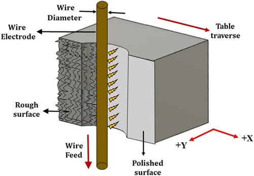
Electrical discharge machining processes are also used to improve the surface properties of printed parts. shows schematic diagram of wire electrical discharge polishing process. The studies on the AM alloys titanium [Citation78–80], aluminium [Citation81] and steel [Citation82] alloys show promising results (75–90% improvement in surface roughness). Electric discharge processes are a more cost-effective solution for machining high hardness materials with excellent end results but are also limited by the accessibility of the electrodes used.
Figure 4. Schematic showing polishing using wire electric.
Chemical and electrochemical polishing are extensively studied methods for polishing AM samples. In chemical polishing, the material is removed by the chemical reaction on the workpiece surface with a polishing medium. In electrochemical polishing, the material is removed by anodic dissolution [Citation83]. shows the results of a comparative study on the effects of chemical and electrochemical polishing on 3D-printed metal parts with different part geometries. Much research has already been done in this field to investigate the possibilities of chemical polishing [Citation84,Citation85] and electrochemical polishing [Citation86–88] and their combinations [Citation85,Citation89] with different electrolytes, materials and processing conditions. Chemical and electrochemical polishing are good tools to achieve better surface quality. However, the toxic chemicals used in this process are harmful. Chemical polishing does not provide much control over the uniformity of material removal [Citation84] and electrochemical polishing has its limitations due to the difficulty of polishing internal cavities and complex features of the printed samples.
Figure 5. Images of AM part showing (a) outer surface and (b) internal surface after electrochemical and chemical polishing, (c) electrochemical polished internal cavity of a part using counter electrode and (d) electrochemical polished internal surface of AM part [Citation83].
![Figure 5. Images of AM part showing (a) outer surface and (b) internal surface after electrochemical and chemical polishing, (c) electrochemical polished internal cavity of a part using counter electrode and (d) electrochemical polished internal surface of AM part [Citation83].](/cms/asset/c9137e22-1057-406a-bfa7-86a45dcf0aed/nvpp_a_2364222_f0005_oc.jpg)
PEP is a special case of electrochemical polishing. Although this technique has been used for surface modification for several decades, PEP has only recently attracted the attention of the AM industry. Due to the excellent bright surface finish that can be achieved with relatively less polishing time and the environmental benefits, PEP is one of the promising post-treatment techniques for AM metal parts. These characteristics of PEP have helped to explore the feasibility of PEP for parts of different materials, shapes, functions and properties.
shows the feasibility of different post-processing techniques for parts with different geometric properties. The methods are tagged feasible, not feasible and neutral for different geometric features. Neutral stands for the possibility to polish such features but with great difficulty or cost or with some limitations. also shows a range of surface roughness values achieved with mentioned post-processing methods from the existing studies. The values are scattered around a range because they are very subjective to the initial surface roughness of the polished sample and duration of polishing, etc. The overall picture from shows that PEP has good potential for most design features and thus can be a good tool for polishing AM metal parts.
Table 1. Comparative analysis of polishing techniques on workpiece geometry across various attributes.
3. PEP: mechanism and machinery
PEP is a special case of anodic dissolution in which both chemical and plasma reactions lead to the levelling of the workpiece surface [Citation33]. There are several interpretations of the mechanisms of material removal that have been explained and illustrated by researchers over the years and are still controversial [Citation92].
PEP is a combination of classical electrolysis and plasma electrolysis. Classical electrolysis involves anodic dissolution and oxidation together with a cathodic reduction process. In plasma electrolysis, a distinction is made between cataphoresis, plasma chemical reactions, diffusion and heating [Citation33]. It is the combination of all these interactions that leads to material removal and produces a high-gloss surface.
A standard setup for PEP is shown in . The workpiece to be polished is anodically polarised and immersed in a suitable aqueous electrolyte solution. A cathode electrode is used in the form of container walls of electrolytic bath or inserted inside the electrolyte. Even if the cathode electrode does not have to correspond to the geometry of the workpiece, the surface ratio between anode and cathode must be greater than 1:10 to ensure the formation of a plasma layer on the polishing sample.
Figure 6. Schematic diagram of PEP setup [Citation93].
![Figure 6. Schematic diagram of PEP setup [Citation93].](/cms/asset/646149e0-dc2d-4c86-baf9-0ff1060f56af/nvpp_a_2364222_f0006_ob.jpg)
The voltage, current density and electrolyte conductance differ for each material–electrolyte combination. When the suitable conditions are met, a vapour gas layer develops around the workpiece in the electrolyte, as shown in , creating a region of the highest resistance and forming a plasma layer [Citation93]. Hence, a virtual cathode is formed at the interface between the vapour gas layer and the electrolyte, and a rapid removal of surface peaks occurs on the anode sample resulting in a smooth surface.
Figure 7. Vapour gas envelope formation during PEP process [Citation93].
![Figure 7. Vapour gas envelope formation during PEP process [Citation93].](/cms/asset/532d3a02-d99c-4bcd-b6b3-fbcd28aff505/nvpp_a_2364222_f0007_ob.jpg)
The PEP machine consists of an energy source unit with transformers, rectifier modules, voltage regulators, an electrolyte interface with heating unit, circulation pump systems and drives for parts handling, as well as safety loops and sensors that enable smooth operation and control (). A 400-litre electrolyte bath system with an 80-kW power module could be approximately 2 m × 1.5 m × 2 m in size and cost around €150k–200k.
4. PEP for metal parts fabricated using AM
PEP, with its ability to create a shiny surface and its greater flexibility in finishing parts with complex designs compared to conventional methods, is proving to be a good polishing technique for AM parts. This section provides an overview of the current research landscape and the impact of PEP on AM parts, as well as the specifics of the research conducted.
4.1 Timeline
Polishing of AM metal parts using PEP has been used initially to process stainless steel X2CrNiMo17-12-2 (AISI: 316L) samples back in 2013 [Citation94]. Since then, many researchers have studied the possibility of PEP as polishing method for metal AM samples for different alloys.
In this section, a brief outlook on the development of the PEP process for AM metal samples is given based on the research contributions. shows a graphical layout that illustrates the path in this research area over the years. It can be seen from the chronology diagram that research interest in this area has increased in recent years. This is mainly due to the increasing popularity of AM and its integration into the manufacturing process chain in many industries. The graphical representation also shows the main area of research and gives aspiring researchers a first impression of the possibilities and focus of the research area. Most of the work has been carried out on stainless steel samples in the early stages of introducing PEP technology into the AM domain. This may be since the composition of the electrolyte is well known. This also helps in the initial feasibility study by comparing the results with other polishing methods as well as with PEP-processed conventional samples. The field of research has recently diversified as authors have investigated the influence of PEP on metal parts produced using different techniques, materials, functions, etc. [Citation95]. Efforts have also been made to investigate the feasibility of modified PEP processes such as jet PEP [Citation96–99] and ultrasonic-assisted PEP [Citation100,Citation101] to overcome the challenges and improve the efficiency of the process. shows a summary of PEP conditions and surface roughness improvement for various metal alloys produced using the AM technique.
Figure 8. Sequential arrangement of research contribution in PEP of AM metal parts.
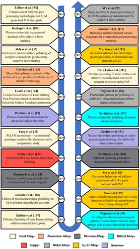
Table 2. Summary of PEP processing conditions and result achieved for different AM metal alloys.
4.2 Enhancing surface finish: PEP in metal AM alloys
shows the summary of surface roughness values represented in roughness average, Ra (arithmetic average of absolute values of roughness along the sampling length [ISO 4287:1997]) and in some cases Sa (arithmetic average of absolute values of roughness over a surface [ISO 25178]) obtained with PEP and PEP in combination with other surface treatment methods for AM metal alloys.
Figure 9. Overview of surface roughness values reported in studies involving PEP of AM samples.
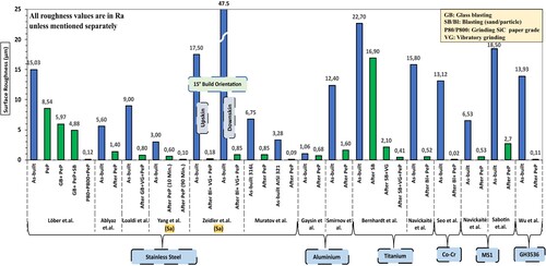
Most of the studies were performed on steel alloys, with a focus on stainless steel. Ti–6Al–4 V, AlSi10Mg, Co–Cr, Copper and nickel alloys have also been investigated by some researchers. The alloy SS316L is one of the most widely used materials in metal AM as it is used in general engineering. It is mainly used in corrosive environments and in the medical field. Hence SS316L is one of the most studied alloys in terms of its properties after different polishing processes.
Löber et al. investigated the influence of PEP on SS316L samples, providing the first major contribution to the PEP of AM samples [Citation94]. The samples were treated with PEP and in combination with other mechanical polishing methods such as grinding and blasting. The results showed that the PEP method in combination with grinding with two different grits gave the highest quality surface with a roughness of almost Ra = 0.12 µm compared to the initial value of Ra = 15.03 µm. The tests were carried out on flat samples and were only possible with such a uniform flat surface. PEP of a complex AISI 316L sample using an electrolyte jet with a pressure of 0.02–0.05 MPa showed a uniform improvement of the inner and outer surface roughness from Ra = 5.6 to 1.4 µm [Citation35]. A final surface roughness of Ra = 0.8 µm compared to the initial value of Ra = 9 µm was achieved by successively applying several processing techniques such as glass blasting, vibratory grinding and plasma polishing [Citation104]. Yang et al. introduced plasma additive layer manufacturing smoothing technology, which is based on the same principle as PEP and provides additional flake filtering and condition monitoring functions to facilitate the polishing of AM parts with high surface roughness [Citation38]. The results show that the initial surface roughness of SS316L samples could be reduced by a factor of 5 within 10 min of polishing (), with no negative impact on surface properties. The study also demonstrated the ability to apply physical vapour deposition coatings to parts polished using above technique. The effect of the PEP process in combination with powder blasting and vibratory grinding to prove that the efficient design of the finishing process chain based on the material removal mechanism can achieve better surface quality in less time than the application of separate machining techniques [Citation107]. The study resulted in a final surface roughness of Sa = 0.18 µm on the top surface and Sa = 0.85 µm on the bottom surface for 316L samples built in 15° orientation with an initial roughness of Sa = 17.5 µm.
Figure 10. SEM images of additively manufactured 316L sample (a) before and (b) after polishing using plasma additive layer manufacturing smoothing technology and (c) surface roughness improvement before and after polishing [Citation38].
![Figure 10. SEM images of additively manufactured 316L sample (a) before and (b) after polishing using plasma additive layer manufacturing smoothing technology and (c) surface roughness improvement before and after polishing [Citation38].](/cms/asset/517a61d9-855a-401d-ae31-5f201e2c8ba7/nvpp_a_2364222_f0010_oc.jpg)
Maraging steel is another steel alloy commonly produced with AM. Ability to incorporate conformal cooling channels, which in turn reduces cycle time, increases productivity, and shortens lead time, has brought AM to the attention of the tooling industry [Citation114]. Maraging steel is widely used, primarily due to its superior strength and high ductility [Citation115]. The investigation of the effect of PEP on laser-printed microfluidic platforms of maraging steel samples with micro features aligned along the X, Y and Z directions showed an improvement in surface finish of approximately 85% within 10 min of processing [Citation106]. The improvement in surface quality with a very short processing time shows the potential of the polishing method. However, as the results of the PEP process are strongly influenced by the initial surface roughness, the combination of PEP with some primary finishing techniques could lead to much better results. This needs to be investigated and quantified in further research. PEP of the inner surface of maraging steel inserts for polymer extrusion with an additional nozzle to improve the electrolyte flow through the insert gap within the electrolyte bath resulted in a reduction of the surface roughness from a maximum of Ra = 6.53 µm to a minimum of Ra = 0.53 µm [Citation116].
AlSi10Mg is the most used material for heat transfer applications due to its high thermal conductivity [Citation117]. It is also used for lightweight applications in the aerospace and automotive industries [Citation118]. Studies on the effect of PEP on AlSi10Mg samples showed an 87% improvement in surface finish from Ra = 12.4 µm in as-built condition to Ra = 1.6 µm after polishing [Citation113].
AM titanium alloys are mainly used in the aerospace, marine, chemical and medical industries due to their excellent mechanical properties, good corrosion resistance and low specific weight [Citation119,Citation120]. Comparative studies on the effect of PEP and a combination of powder blasting and PEP on the surface roughness of printed Ti–6AL–4 V samples [Citation110] showed up to 96.7% reduction in surface roughness after polishing with PEP or a combination of powder blasting and PEP (Ra = 15.7 µm to Ra = 0.6 µm). In another study investigating AM samples of Ti–6Al–4 V polished with various combinations of sandblasting, vibratory grinding and plasma polishing produced samples with final roughness Ra < 0.5 µm () and wettability suitable for medical implants [Citation105].
Figure 11. SEM images and surface topographies of Titanium alloy at different stages of polishing: (a) As-built, (b) Sand blasted, (c) Sand Blasted + PEP, (d) Sand blasted + Vibratory Grounded + PEP [Citation105].
![Figure 11. SEM images and surface topographies of Titanium alloy at different stages of polishing: (a) As-built, (b) Sand blasted, (c) Sand Blasted + PEP, (d) Sand blasted + Vibratory Grounded + PEP [Citation105].](/cms/asset/974f451d-0cda-4f08-b0b4-abd1ad898830/nvpp_a_2364222_f0011_oc.jpg)
Co–Cr alloys are one of the most popular metallic biocompatible materials due to their good corrosion and wear properties [Citation121]. Seo et al. [Citation109] investigated the influence of PEP on Co–Cr alloy sample manufactured using AM. The as-built samples with surface roughness Ra = 13.12 µm were blasted to bring the roughness to 3 µm. These samples were further polished with PEP for 8 min to produce roughness, Ra = 0.015 µm. Blasted samples were also mechanically polished using SiC papers of grit size 400–2400 to achieve similar roughness around Ra = 0.02 µm. Even with similar surface roughness values, mechanically polished samples showed surface morphology with scratches aligned to polishing directions and PEP surface produced smooth surface with numerous microscopic vertically aligned pillars as shown in . Authors also noted that PEP-treated samples showed better corrosion resistance than the mechanically polished samples.
Figure 12. Surface profilometer images of (a) as built and (b) blasted Co–Cr alloys and atomic force microscopy images showing the reduced surface roughness by (c) the mechanically polished and (d) plasma electrolytic polished Co-Cr alloys [Citation109].
![Figure 12. Surface profilometer images of (a) as built and (b) blasted Co–Cr alloys and atomic force microscopy images showing the reduced surface roughness by (c) the mechanically polished and (d) plasma electrolytic polished Co-Cr alloys [Citation109].](/cms/asset/5cf29e2f-99de-4d74-a24e-3ece02d54437/nvpp_a_2364222_f0012_oc.jpg)
Nickel–titanium alloys, also known as nitinol, are shape memory alloys that are difficult to produce conventionally. Nitinol is mainly used in aerospace and medical applications due to its shape memory effect, superelasticity behaviour, low stiffness, biocompatibility and excellent corrosion resistance [Citation122]. AM has enabled the production of complex nitinol parts and thus expanded the application potential in relevant areas.
PEP studies on AM nitinol springs showed the partially molten powder particles adhering to the spring surface were removed by polishing for 10 min and further smoothed by longer polishing () [Citation36]. Navickaite et al. performed PEP on porous nitinol structures like the trabecular bone profiles (). The study aimed to investigate the depth of polishing, the effects on the chemical composition and the influence on the transition temperature of 50% porous nitinol cubes of size 20 mm3 [Citation37]. Results showed PEP could only penetrate very little into the part core and is largely dependent on the free passage for electrolyte flow and formed vapour to escape. No influence on transition temperature or chemical composition of the part was observed.
Figure 13. SEM images of nitinol spring lateral surface in (a) as built, (b) after 10 min. PEP and (c) after 20 min. PEP [Citation36].
![Figure 13. SEM images of nitinol spring lateral surface in (a) as built, (b) after 10 min. PEP and (c) after 20 min. PEP [Citation36].](/cms/asset/4f0a301a-b258-40ab-8a5e-6db76918a6aa/nvpp_a_2364222_f0013_oc.jpg)
Wu et al. used the spray electrolyte plasma polishing technique to process the AM high-temperature nickel superalloy GH3536, which is used in aircraft engine combustion chambers and other high-temperature applications [Citation97]. shows the equipment used for polishing. The spray electrolyte plasma polishing system uses a spray head as a cathode, which replaces the traditional electrolyte bath in PEP. The spray head is connected to a six-joint robot and directs its outlet onto the surface of the workpiece. By applying a voltage, a strong electric field is generated for localised polishing, limiting the current to less than 50 A. Precise control of the robot and turntable enables efficient polishing of large and complex workpieces by focusing on small areas at a time. The results show that the surface roughness could be reduced from an initial value of Ra = 13.93 µm to Ra = 0.107 µm, resulting in a shiny surface without machining marks.
Figure 14. Spray electrolyte plasma polishing setup [Citation97].
![Figure 14. Spray electrolyte plasma polishing setup [Citation97].](/cms/asset/56672971-2f90-44c3-97bb-128c635369d8/nvpp_a_2364222_f0014_oc.jpg)
Copper and its alloys are widely used in industry due to their excellent thermal and electrical conductivity. The AM of copper is not as popular as that AM of other metal alloys due to its high reflectivity of near-infrared radiation [Citation123]. However, researchers have developed various methods to mitigate the problems and are now catching up with other metal alloys. PEP on AM copper parts is not yet well researched. Zeidler et al. investigated the influence of electrolyte flow under ultrasonic vibrations in cavities of different sizes (0.8–1.9 mm gap and 10 × 10 mm2 cross-section) prepared on an AM copper part [Citation124]. The study showed differences in material removal depending on the direction of electrolyte flow. A longer polishing time (4 min) under ultrasonic vibrations had a positive effect on the cavities, and PEP of gaps with a size of 1.3 mm is successful when that is sufficient electrolyte exchange.
The use of PEP on AM parts is often combined with other finishing techniques due to the high surface roughness that is present on AM parts. Therefore, a post-processing method with higher material removal rate and subsequent PEP to obtain a bright finish would be an ideal sequence of post-processing steps to improve the surface quality of AM parts [Citation107].
Extensive research in this area is introducing process conditions for polishing new materials and new functional parts that expand the portfolio of polishable metals for PEP. This broader applicability is helping PEP to become more widely recognised as a post-processing solution for additively manufactured metal materials.
4.3 Influence of PEP on material properties.
Significant number of studies are concentrated on the surface quality enhancement capabilities of PEP. As the parts during polishing are not heated up beyond the boiling point of electrolyte (which is predominantly water) [Citation33,Citation125], the material properties of part being polished are expected to be un-altered. Only a few studies explore the influence of PEP on some material properties of various metal parts fabricated using AM.
Yang et al. [Citation38] and Wu et al. [Citation97] studied the influence of PEP on micro hardness of steel and nickel alloys respectively. Yang et al. observed slight improvement in the surface micro hardness and speculates the reason to be due to the presence of enriched chromium contentment observed in XRD analysis on the surface due its lower susceptibility to electro dissolution than iron. Wu et al. performed Rockwell hardness test with 150 kgfFootnote2 on GH3536 duper alloy and noticed lower inconsistent values before plasma polishing and approximately consistent values around 30 HRc after polishing due to smooth and flat surface.
Another interesting observation regarding spring rate after PEP polishing is reported [Citation36]. Nitinol spring polished using PEP showed considerable reduction in spring rate as it is related to the diameter. The spring rate was reduced by 22% in the initial 10 min of polishing and around 40% at the end of 20 min of polishing. The material removal must be considered in case of such functional parts and the authors propose the scaling of the part to accommodate this reduction in diameter based on the MRR studies conducted.
Fatigue properties of AM Ti–6Al–4 V part was compared after particle blasting and PEP in combination with particle blasting [Citation110]. The use of particle blasting before PEP reduced the PEP time by 8 min to achieve the same surface roughness, but at the expense of lower fatigue properties than with only PEP. The samples were cyclically loaded with the constant amplitude of R = 0.1 with peak load of 11.793 kN. The results showed an improvement in fatigue resistance of 2.4 times after PEP and 1.9 times after a combination of blasting and PEP.
Corrosion resistance studies on Co–Cr samples manufactured by AM and polished using PEP showed better corrosion resistance than the mechanically polished samples [Citation109]. A comparative study on Co–Cr samples polished mechanically and PEP were performed as discussed in Section 4.2. TEM images of the sample surface show continuous oxide layer formed after PEP () which is beneficial for strengthening the corrosion resistance. The high-quality oxide film formed during the PEP process was verified based on its stable open circuit potential, higher oxide resistance and charge transfer resistance.
Figure 15. TEM images showing the formation of the oxide film on the CoCr alloy polished with (a) mechanical polishing and (b) plasma electrolytic polishing [Citation109].
![Figure 15. TEM images showing the formation of the oxide film on the CoCr alloy polished with (a) mechanical polishing and (b) plasma electrolytic polishing [Citation109].](/cms/asset/cc9523b9-d88b-46b9-b69c-409443043eee/nvpp_a_2364222_f0015_oc.jpg)
The biocompatibility of parts polished with PEP is investigated to assess their applicability in the medical field. The studies on conventional samples after PEP show no adverse effects on cell life [Citation126,Citation127]. However, Bernhardt et al. found cytotoxic effects on AM Ti–6Al–4 V samples polished with PEP [Citation105] due to the increased presence of vanadium on the PEP-treated surface. The authors hypothesise that these potentially cytotoxic elements can be removed by washing steps prior to application, as the vanadium content in the cell culture medium was significantly reduced during prolonged cultivation, which is an ultimate prerequisite for application as customised medical devices.
4.4 AM peculiarities addressed in the PEP studies
The metal AM process facilitates the fabrication of components characterised by exceptional intricacy, owing to its distinctive manufacturing methodologies. This complexity is often accompanied by difficulties in post-processing or polishing the printed parts. This section summarises various features of an AM part that have been explored using the PEP method.
The surface roughness of a 3D-printed metal part is influenced by many factors, such as the layer thickness, powder quality, laser power, scanning speed, build orientation and shape of the part and so on. The final surface roughness of the part is often affected by adjusting parameters to increase productivity and reduce costs. A well-designed post-processing chain could solve this problem and bring the surface quality to the desired level.
Ablyaz et al. investigated the influence of PEP on a complex SLM printed part [Citation35]. Both the immersion of the workpiece in the electrolyte and the spraying of the electrolyte onto the workpiece were tested. The results showed that the immersion-based technique only produced a good surface finish on the outer surface, while the spraying technique with a pressure of 0.02–0.05 MPa provided a stable and uniform polish of the inner and outer surfaces. A final surface finish of Ra = 1.4 μm was achieved, compared to the initial surface roughness Ra = 5.6 μm.
The production of parts with lattice structures is one of the main specialties of AM technology. This enables fabrication of parts with a lower weight while maintaining the required rigidity. Lattice structures are quite complex geometries that cannot be polished using conventional methods. The lattice structures of an AlSi10Mg and a porous Nitinol sample produced using laser powder bed fusion technology, as shown in , were investigated for the effectiveness of PEP [Citation37,Citation103]. The study on the AlSi10Mg part with a hexagonal lattice region [Citation103] showed a considerable improvement in surface qualities by removing partially melted powder particles and creating clean, sharp surface profiles, as shown in .
Figure 16. AM samples with lattice structures made of (a) AlSi10Mg and (b) Nitinol [Citation37,Citation103].
![Figure 16. AM samples with lattice structures made of (a) AlSi10Mg and (b) Nitinol [Citation37,Citation103].](/cms/asset/ae69da08-895a-4563-957f-226930ca1b30/nvpp_a_2364222_f0016_oc.jpg)
Porous nitinol cubes of size 20 mm × 20 mm × 20 mm with a porosity of 50% and a knot diameter of 300 µm were polished at 330 V and 60–240 s polishing time [Citation37].
The results showed that PEP can peripherally polish such samples and has no effect after a certain depth. The polishing depth depends on the orientation of the part in the electrolytic bath and the electrolyte flow inside the part. This indicates that PEP can only reach the inner regions of lattice structures to a limited extent when the filling density is very high or the space between the branches/struts is very narrow ().
Figure 17. SEM images showing surface of AlSi10Mg part (a, b) before and (c, d) after PEP [Citation103].
![Figure 17. SEM images showing surface of AlSi10Mg part (a, b) before and (c, d) after PEP [Citation103].](/cms/asset/cfb62257-9b57-45ed-9d3b-f69299efba56/nvpp_a_2364222_f0017_ob.jpg)
The up-skin and down-skin properties of a printed pattern are special features that can only be seen in AM. On the up-skin, heat conduction occurs mainly through the previously solidified printed layer, whereas on the down-skin it occurs through the powder. This difference in heat conduction is one of the main reasons for the higher surface roughness on the undersides, which leads to an uneven surface quality [Citation128]. Investigations on Nitinol springs, in which the surface was divided into up-skin, lateral and down-skin areas [Citation36], showed that the quality of the polished surface in the down-skin area is inadequate (). It was concluded that a clean mechanical removal of the support structures before the PEP is necessary for a uniform surface quality.
Figure 18. SEM images of detailed surface features on the (a) lateral, (b) up- and (c) down-skin of the nitinol spring after10 min of PEP [Citation36].
![Figure 18. SEM images of detailed surface features on the (a) lateral, (b) up- and (c) down-skin of the nitinol spring after10 min of PEP [Citation36].](/cms/asset/5dd86c79-1fea-4f9a-8017-6ad28bfc5df2/nvpp_a_2364222_f0018_ob.jpg)
Zeidler et al. studied the influence of post-processing techniques on the up-skin and down-skin surface qualities of additively manufactured 316L samples. The samples were fabricated in different orientations from 0° to 90°. Three different processing methods, particle blasting, vibratory grinding and PeP were used to find the best combination producing most roughness reduction. A combination of particle blasting (2 min), vibratory finishing (180 min) and PEP (10 min) [Citation107] showed the most significant reduction (Sa < 1μm) of surface roughness on the up-skin and down-skin region of samples printed with 15°, 45° and 90° orientations. However, the inherent difference in surface roughness of the up-skin and down-skin properties persisted until the finishing step and could only achieve a uniform surface finish with prolonged polishing. Microscopic waviness presents especially on the down-skin surfaces of the propeller blades polished using the combinations of particle blasting, vibratory grinding and PeP is shown in .
Figure 19. Microscopic waviness of propeller blades after processing with combination of particle blasting, vibratory grinding and PEP [Citation107].
![Figure 19. Microscopic waviness of propeller blades after processing with combination of particle blasting, vibratory grinding and PEP [Citation107].](/cms/asset/be92ab11-05e8-40b3-be04-52c9967c1600/nvpp_a_2364222_f0019_oc.jpg)
These studies demonstrate the opportunities and challenges of the PEP process in addressing the unique surface and geometry characteristics of parts manufactured with AM. The results also indicate the potential of the process in selectively overcoming the challenges and the scope for improvement through further systematic research.
4.5 Challenges and limitations of PEP in polishing AM parts
PEP is relatively new to the field of AM compared to other existing surface finishing techniques and therefore research is underway to adapt the process to AM parts to maximise its potential.
PEP is not sufficient to reduce the higher surface roughness of AM parts. PEP should be used as the final process to achieve extremely smooth surfaces. Using PEP alone would take much more time than combining it with a suitable post-processing technique to reduce the initial high roughness.
Another factor to consider when using PEP is the size of the sample. A larger surface area of the sample means that a high-power supply is required to initiate the PEP process. A machine power of 80 kW could process parts with a surface area of about 2000 cm2 when applying voltage of 400 V. The parts with larger surface area polished in several steps, thus avoiding immersing the sample completely, but polish the entire surface gradually. Jet PEP systems are another alternative to effectively increase the size of polishable parts with energy systems like those used in immersion technology [Citation96–99]. However, this system is comparatively much more complex than the immersion-based system and requires more study to determine the operating parameters for different materials to be used robustly.
AM parts are often produced with integrating design for additive manufacturing features [Citation129]. This helps to exploit the full potential of the technology while minimising material consumption and improving functionality. Features such as conformal cooling channels [Citation130–132], micro- and macro channels [Citation133–135] are being widely explored for heat transfer and chemical applications. In the simpler immersion methods, PEP is limited in its ability to reach complicated cavities due to the Faraday cage effects and restrictions in effective removal of vapour formed [Citation37]. This would mean adaptation of modifications like forced electrolyte flow [Citation116] and ultrasonic-assisted PEP [Citation100,Citation101,Citation124].
The lack of established electrolyte combinations for all AM metal alloys poses a further challenge. Increased research interest could potentially improve the material portfolio. However, optimisation of process parameters would require the polishing window for special alloys used for AM to be definitively established.
Existing PEP investigations for AM metal parts are only on the parts manufactured by PBF technique. This is mainly because parts produced using DED techniques have a much higher surface waviness [Citation136,Citation137] than PBF methods. Material removal with PEP is very low and is mainly used for finishing. PEP polishing can effectively impart a shiny surface to parts produced by the DED method and leave the waviness behind. PEP can therefore not be used directly after the manufacturing process, as the parts often still need to be machined to give them their exact shape [Citation137–139]. PEP can be used as a sequential finishing process to achieve the final smooth surface.
5. Prospects and possibilities in PEP research
The need for post-processing of AM metal parts is increasing enormously with the widespread acceptance and application of the technology. This growing market for AM will support the development of PEP technology as it is an environmentally friendly polishing process that has enormous potential to solve various problems.
The industry is always looking to optimise machines and simplify the manual interactions required to achieve the result. With the advanced technologies at our disposal, we can use robotic arms to change the orientation of a part in the electrolyte bath in a predetermined sequence based on the intricate features of the workpiece to ensure uniform polishing with minimum idle time and maximum productivity. In addition, the PEP process window is defined with a specific electrolyte temperature range that provides the best results [Citation140]. PEP is performed in steps of a few seconds or minutes to maintain the electrolyte temperature range as the temperature rises during the PEP process. A suitable recirculation system for cooling or a reserve tank system that provides cool electrolytes triggered by the thermocouple readings could extend the polishing time without having to shorten the polishing steps to cool the electrolyte before the next polishing step.
The PEP method swiftly imparts glossiness to smooth surfaces, requiring less than 30 s of polishing. It serves as potential alternative for parts currently subjected to buffing, electroplating, and deposition techniques for achieving a shiny finish. Depending on power capacity, multiple parts can undergo processing simultaneously, provided the total surface area remains within prescribed limits. Alternatively, the part-handling system may be enhanced to accommodate multiple parts successively, eliminating the need for reloading after each piece is polished. This helps in scaling up the processing capacity of PEP and improve the overall productivity.
When the initial surface conditions vary, the uniformity of surface roughness after PEP depends on the duration of polishing. In these cases, prolonged polishing will result in excessive material removal and a significant change in the dimensions of the workpiece or feature. Experimental data on the material removal and final surface quality achieved under different polishing conditions can be used to standardise the rescaling factor for part features for specific materials. This helps in modifying the CAD model to achieve the desired surface quality after PEP without violating dimensional tolerance constraints.
As explained in Sections 4.2 and 4.3, the difference in surface quality of the upper and lower skin is an important factor for PEP. Since this polishing method is affected by the bubble formation and its movement along the surface of the workpiece, investigating the influence of the orientation of the printed samples to overcome this challenge by utilising the inherent phenomenon in the electrolysis bath would save a lot of design time to avoid the uneven surface roughness of the polishing samples.
There is a lack of simulation models to predict the behaviour of polished samples under different polishing conditions. Developing an analytical model that mimics the polishing process could help in predicting the effects of different polishing conditions and fine-tuning before validation with the experimental results.
During the PEP process, the bubbles that form near the surface of the workpiece migrate upwards and merge into larger bubbles. As a result, the vapour gas envelope remains thinnest in the lower area, which leads to a higher removal rate. This affects the uniform polishing along the surface. Ultrasonic-assisted PEP showed possible improvement in narrow channels by facilitating sufficient electrolyte exchange [Citation124]. Similar forced electrolyte flow across the polishing sample could influence the quick removal of bubbles formed and achieve a more uniform polishing throughout. A simulation-based approach to investigate the influence of an external electrolyte motion under different conditions will help us to explore PEP setups to cope with the structural complexities of the printed samples.
There are only a few studies investigating the jet PEP process in AM [Citation96,Citation97]. AM, known for its flexibility in producing parts with complex geometries, could be best combined with the jet PEP process, which offers more control over local polishing and increases the machinable surface area of the part. The level of automation of such systems is higher as the simultaneous movement of the parts and the polishing head could overcome the limitations that exist with immersion-based PEP processes.
PEP is not yet as popular as similar surface treatment methods for AM metal parts. This is because the field is comparatively new as a potential alternative. There are very few research institutions around the world actively contributing to the field of PEP for AM parts. Active collaboration with industry could provide the opportunity to introduce the true potential of PEP to a wider audience and generate more research interest in this topic. More research into interesting material alloys that are widely used in the additive industry and how to overcome the unique challenges of AM metal parts could potentially accelerate the progress of PEP in this field.
6. Conclusion
PEP as a post-processing technique for metals and alloys has already been established for several decades. However, the application of PEP for the polishing of AM metal parts is a relatively new field of research, and the intensive research in this area can be seen from the considerable increase in publications in recent years. As AM is mainly used to produce parts with complex shapes and features to maximise the flexibility of the process, there are challenges in terms of surface quality after finishing due to the nature of the process mechanisms. The PEP process is an environmentally friendly solution to achieve a fine glossy surface and is considered one of the best alternatives to current practices in this field. The available studies highlight experimental and theoretical opportunities to explore the process to improve the material portfolio and the ability to overcome the various challenges faced by complex parts produced using metal AM techniques. Given the increasing popularity and use of AM components, conducting additional research and investigation into the effects of PEP on the post-processing properties of printed parts can play a critical role in addressing current challenges. Furthermore, such studies can open new opportunities for the integration of metal AM parts into a wider range of industries and applications.
Acknowledgement
The authors acknowledge the support of the European Research Executive Agency under the Horizon Europe: Widening participation and spreading excellence (SEAMAC, 101079481) and the Slovenian Research Agency in the frame of Research program Innovative production systems and processes, Grant P2-0248.
Data availability
The data that support the findings of this study are openly available in the repository managed by Zenodo at https://zenodo.org/doi/ 10.5281/zenodo.10781367
.Disclosure statement
No potential conflict of interest was reported by the author(s).
Additional information
Funding
Notes
1 In the provided paper, the term ‘fused deposition modelling’ was used, but here we used a term according to the standard ISO ASTM 52900-2022.
2 Equal to 1471 N.
References
- Hull CW. Apparatus for production of three-dimensional objects by stereolithography, 1986.
- Ngo TD, Kashani A, Imbalzano G, et al. Additive manufacturing (3D printing): a review of materials, methods, applications and challenges. Compos B Eng. 2018;143:172–196. doi:10.1016/j.compositesb.2018.02.012
- Omiyale BO, Olugbade TO, Abioye TE, et al. Wire arc additive manufacturing of aluminium alloys for aerospace and automotive applications: a review. Mater Sci Technol. 2022;38:391–408. doi:10.1080/02670836.2022.2045549
- Vasco JC. Additive manufacturing for the automotive industry. Addit Manuf. 2021: 505–530. doi:10.1016/B978-0-12-818411-0.00010-0
- Zhao N, Parthasarathy M, Patil S, et al. Direct additive manufacturing of metal parts for automotive applications. J Manuf Syst. 2023;68:368–375. doi:10.1016/j.jmsy.2023.04.008
- Veeman D, Mahesh VS, Madabushi SS, et al. Additive manufacturing and its need, role, applications in the automotive industry. 2021: pp. 358–367. https://doi.org/10.4018/978-1-7998-4939-1.ch017
- Blakey-Milner BA, Gradl PR, Snedden GC, et al. Metal additive manufacturing in aerospace: a review. Mater Des. 2021;209:110008. https://api.semanticscholar.org/CorpusID:237670030.
- Najmon JC, Raeisi S, Tovar A. Review of additive manufacturing technologies and applications in the aerospace industry. Addit Manuf Aerospace Ind. 2019. https://api.semanticscholar.org/CorpusID:115292453.
- Liu R, Wang Z, Sparks T, et al. Aerospace applications of laser additive manufacturing. 2017. https://api.semanticscholar.org/CorpusID:113601331
- Uriondo A, Esperon-Miguez M, Perinpanayagam S. The present and future of additive manufacturing in the aerospace sector: a review of important aspects. Proc Inst Mech Eng G J Aerosp Eng. 2015;229:2132–2147. https://api.semanticscholar.org/CorpusID:137549412
- Javaid M, Haleem A. Additive manufacturing applications in medical cases: a literature based review. Alexandria J Med. 2018;54:411–422. doi:10.1016/j.ajme.2017.09.003
- Lakkala P, Munnangi SR, Bandari S, et al. Additive manufacturing technologies with emphasis on stereolithography 3D printing in pharmaceutical and medical applications: a review. Int J Pharm. 2023;5. https://api.semanticscholar.org/CorpusID:255566499
- Youssef A, Hollister SJ, Dalton PD. Additive manufacturing of polymer melts for implantable medical devices and scaffolds. Biofabrication. 2017;9. https://api.semanticscholar.org/CorpusID:52835412
- Culmone C, Smit G, Breedveld P. Additive manufacturing of medical instruments: a state-of-the-art review. Addit Manuf. 2019. https://api.semanticscholar.org/CorpusID:164598350
- Salmi M. Additive Manufacturing Processes in Medical Applications. Materials (Basel). 2021;14. https://api.semanticscholar.org/CorpusID:230784658
- Tay YWD, Panda B, Leong KF. 3D printing trends in building and construction industry: a review. Virtual Phys Prototyp. 2017;12:261–276. doi:10.1080/17452759.2017.1326724
- Camacho DD, Clayton P, O’brien WJ, et al. Applications of additive manufacturing in the construction industry – a forward-looking review. Autom Constr. 2018;89:110–119. https://api.semanticscholar.org/CorpusID:117365755
- Bos FP, Wolfs R, Ahmed ZY, et al. Additive manufacturing of concrete in construction: potentials and challenges of 3D concrete printing. Virtual Phys Prototyp. 2016;11:209–225. https://api.semanticscholar.org/CorpusID:114225843
- Paul AA, Aladese AD, Marks RS. Additive manufacturing applications in biosensors technologies. Biosensors (Basel). 2024;14:60. doi:10.3390/bios14020060
- Tan TTHW, Chua CK. A review of printed passive electronic components through fully additive manufacturing methods. Virtual Phys Prototyp. 2016;11:271–288. doi:10.1080/17452759.2016.1217586
- Ficzere P. Additive manufacturing in the military and defence industry. Design of Machines and Structures. 2022. https://api.semanticscholar.org/CorpusID:253614005
- Segonds F. Design by additive manufacturing: an application in aeronautics and defence. Virtual Phys Prototyp. 2018;13:237–245. doi:10.1080/17452759.2018.1498660
- Gonzaga E, Tuazon BJ, Garcia JAV, et al. Additive manufacturing applications in maritime education. Diffusion Found Mater Appl. 2023;32:19–26. doi:10.4028/p-kt7n60
- Rouway M, Tarfaoui M, Chakhchaoui N, et al. Additive manufacturing and composite materials for marine energy: case of tidal turbine., 3D Print. Addit Manuf. 2021;10(6):1309–1319. https://api.semanticscholar.org/CorpusID:266372695.
- Marchese SS, Epasto G, Crupi V, et al. Tensile response of fibre-reinforced plastics produced by additive manufacturing for marine applications. J Mar Sci Eng. 2023. https://api.semanticscholar.org/CorpusID:256651826
- Vishnukumar M, Pramod R, Kannan AR. Wire arc additive manufacturing for repairing aluminium structures in marine applications. Mater Lett. 2021;299:130112. https://api.semanticscholar.org/CorpusID:236396094
- Saheb SH, Kumar JV. A comprehensive review on additive manufacturing applications, in: 2020: p. 020024. https://doi.org/10.1063/5.0026202
- Milewski JO. Additive manufacturing of metals: from fundamental technology to rocket nozzles, medical implants, and custom jewelry. Addit Manuf Metals. 2017. https://api.semanticscholar.org/CorpusID:136050727
- Di̇lek E, Yıldırım M, Uzun M. Additive manufacturing (3D printing) in technical fashion industry applications, in: 2021. https://api.semanticscholar.org/CorpusID:237346095
- Akhoundi B. A mini-review of using additive manufacturing in the fashion & textile industry? Trends Textile Eng Fashion Technol. 2023. https://api.semanticscholar.org/CorpusID:259806315
- DebRoy T, Wei HL, Zuback JS, et al. Additive manufacturing of metallic components – process, structure and properties. Prog Mater Sci. 2018;92:112–224. doi:10.1016/j.pmatsci.2017.10.001
- Boban J, Ahmed A, Jithinraj EK, et al. Polishing of additive manufactured metallic components: retrospect on existing methods and future prospects. Int J Adv Manuf Technol. 2022;121:83–125. doi:10.1007/s00170-022-09382-y
- Nestler K, Böttger-Hiller F, Adamitzki W, et al. Plasma electrolytic polishing – an overview of applied technologies and current challenges to extend the polishable material range. Proc CIRP. 2016;42:503–507. doi:10.1016/j.procir.2016.02.240
- Chen HL, Zhang YX. Eco-friendly oxalic acid and citric acid mixed electrolytes using for plasma electrolytic polishing 304 stainless steel. J Phys Conf Ser. 2022;2345:012029. doi:10.1088/1742-6596/2345/1/012029
- Ablyaz TR, Muratov KR, Radkevich MM, et al. Electrolytic plasma surface polishing of complex components produced by selective laser melting. Russ Eng Res. 2018;38:491–492. doi:10.3103/S1068798X18060035
- Stepputat VN, Zeidler H, Safranchik D, et al. Investigation of post-processing of additively manufactured nitinol smart springs with plasma-electrolytic polishing. Materials (Basel). 2021;14:4093. doi:10.3390/ma14154093
- Navickaitė K, Roßmann K, Nestler K, et al. Plasma electrolytic polishing of porous nitinol structures. Plasma. 2022;5:555–568. doi:10.3390/plasma5040039
- Yang L, Laugel N, Housden J, et al. Plasma additive layer manufacture smoothing (PALMS) technology – an industrial prototype machine development and a comparative study on both additive manufactured and conventional machined AISI 316 stainless steel. Addit Manuf. 2020;34:101204. doi:10.1016/j.addma.2020.101204
- Jian-Yuan Lee APN, Yeo SH. A review on the state-of-the-art of surface finishing processes and related ISO/ASTM standards for metal additive manufactured components. Virtual Phys Prototyp. 2021;16:68–96. doi:10.1080/17452759.2020.1830346
- Hashmi AW, Mali HS, Kunkel ME. Surface characteristics improvement methods for metal additively manufactured parts: a review. Adv Mater Process Technol. 2022;8:4524–4563. doi:10.1080/2374068X.2022.2077535
- Ye C, Zhang C, Zhao J, et al. Effects of post-processing on the surface finish, porosity, residual stresses, and fatigue performance of additive manufactured metals: a review. J Mater Eng Perform. 2021;30:6407–6425. https://api.semanticscholar.org/CorpusID:236438140
- Peng X, Kong LB, Fuh JYH, et al. A review of post-processing technologies in additive manufacturing. in: 2021. https://api.semanticscholar.org/CorpusID:234847569
- Khan HM, Karabulut Y, Kitay O, et al. Influence of the post-processing operations on surface integrity of metal components produced by laser powder bed fusion additive manufacturing: a review. Mach Sci Technol. 2020;25:118–176. https://api.semanticscholar.org/CorpusID:231741715
- Kumbhar NN, Mulay AV. Post processing methods used to improve surface finish of products which are manufactured by additive manufacturing technologies: a review. J Instit Eng India Ser C. 2018;99:481–487. https://api.semanticscholar.org/CorpusID:115005424
- Demisse W, Xu J, Rice L, et al. Review of internal and external surface finishing technologies for additively manufactured metallic alloys components and new frontiers. Progr Addit Manuf. 2023;8:1433–1453. doi:10.1007/s40964-023-00412-z
- Shi D, Gibson I. Improving surface quality of selective laser sintered rapid prototype parts using robotic finishing. Proc Inst Mech Eng B J Eng Manuf. 2000;214:197–203. doi:10.1243/0954405001517586
- Ramos-Grez JA, Bourell DL. Reducing surface roughness of metallic freeform-fabricated parts using non-tactile finishing methods. Int J Mater Prod Technol. 2004;21:297. doi:10.1504/IJMPT.2004.004944
- Alrbaey K, Wimpenny D, Tosi R, et al. On optimization of surface roughness of selective laser melted stainless steel parts: a statistical study. J Mater Eng Perform. 2014;23:2139–2148. doi:10.1007/s11665-014-0993-9
- Vaithilingam J, Goodridge RD, Hague RJM, et al. The effect of laser remelting on the surface chemistry of Ti6al4V components fabricated by selective laser melting. J Mater Process Technol. 2016;232:1–8. doi:10.1016/j.jmatprotec.2016.01.022
- Yasa E, Deckers J, Kruth J. The investigation of the influence of laser re-melting on density, surface quality and microstructure of selective laser melting parts. Rapid Prototyp J. 2011;17:312–327. doi:10.1108/13552541111156450
- Morgan RH, Papworth AJ, Sutcliffe C, et al. High density net shape components by direct laser re-melting of single-phase powders. J Mater Sci. 2002;37:3093–3100. doi:10.1023/A:1016185606642.
- Simoni F, Huxol A, Villmer F-J. Improving surface quality in selective laser melting based tool making. J Intell Manuf. 2021;32:1927–1938. doi:10.1007/s10845-021-01744-9
- Schanz J, Hofele M, Hitzler L, et al. Erratum to: Laser polishing of additive manufactured AlSi10Mg parts with an oscillating laser beam. in: 2016: pp. E3–E3. https://doi.org/10.1007/978-981-10-1082-8_19
- Alfieri V, Argenio P, Caiazzo F, et al. Reduction of surface roughness by means of laser processing over additive manufacturing metal parts. Materials (Basel). 2016;10:30. doi:10.3390/ma10010030
- Ma CP, Guan YC, Zhou W. Laser polishing of additive manufactured Ti alloys. Opt Lasers Eng. 2017;93:171–177. doi:10.1016/j.optlaseng.2017.02.005
- Zhihao F, Libin L, Longfei C, et al. Laser polishing of additive manufactured superalloy. Proc CIRP. 2018;71:150–154. doi:10.1016/j.procir.2018.05.088
- Worts N, Jones J, Squier J. Surface structure modification of additively manufactured titanium components via femtosecond laser micromachining. Opt Commun. 2019;430:352–357. doi:10.1016/j.optcom.2018.08.055
- Bhaduri D, Ghara T, Penchev P, et al. Pulsed laser polishing of selective laser melted aluminium alloy parts. Appl Surf Sci. 2021;558:149887. doi:10.1016/j.apsusc.2021.149887
- Han S, Salvatore F, Rech J, et al. Abrasive flow machining (AFM) finishing of conformal cooling channels created by selective laser melting (SLM). Precis Eng. 2020;64:20–33. doi:10.1016/j.precisioneng.2020.03.006
- Bouland C, Urlea V, Beaubier K, et al. Abrasive flow machining of laser powder bed-fused parts: numerical modeling and experimental validation. J Mater Process Technol. 2019;273:116262. doi:10.1016/j.jmatprotec.2019.116262
- Peng C, Fu Y, Wei H, et al. Study on improvement of surface roughness and induced residual stress for additively manufactured metal parts by abrasive flow machining. Proc CIRP. 2018;71:386–389. doi:10.1016/j.procir.2018.05.046
- Duval-Chaneac MS, Han S, Claudin C, et al. Characterization of maraging steel 300 internal surface created by selective laser melting (SLM) after abrasive flow machining (AFM). Procedia CIRP. 2018;77:359–362. doi:10.1016/j.procir.2018.09.035
- Sehijpal Singh HSS, Kumar P. Experimental studies on mechanism of material removal in abrasive flow machining process. Mater Manuf Process. 2008;23:714–718. doi:10.1080/10426910802317110
- Atzeni E, Barletta M, Calignano F, et al. Abrasive fluidized bed (AFB) finishing of AlSi10Mg substrates manufactured by direct metal laser sintering (DMLS). Addit Manuf. 2016;10:15–23. doi:10.1016/j.addma.2016.01.005
- Karakurt I, Ho KY, Ledford C, et al. Development of a magnetically driven abrasive polishing process for additively manufactured copper structures. Proc Manuf. 2018;26:798–805. doi:10.1016/j.promfg.2018.07.097
- Zhang J, Chaudhari A, Wang H. Surface quality and material removal in magnetic abrasive finishing of selective laser melted 316L stainless steel. J Manuf Process. 2019;45:710–719. doi:10.1016/j.jmapro.2019.07.044
- Tan KL, Yeo SH. Surface modification of additive manufactured components by ultrasonic cavitation abrasive finishing. Wear. 2017;378–379:90–95. doi:10.1016/j.wear.2017.02.030.
- Liu X, Wang J, Zhu J, et al. Ultrasonic abrasive polishing of additive manufactured parts: an experimental study on the effects of process parameters on polishing performance. Adv Product Eng Manage. 2022. https://api.semanticscholar.org/CorpusID:252443008
- Nagalingam AP, Yeo SH. Controlled hydrodynamic cavitation erosion with abrasive particles for internal surface modification of additive manufactured components. Wear. 2018;414–415:89–100. doi:10.1016/j.wear.2018.08.006.
- Prasanth AS, Thiruchelvam C, Yuvaraj HK, et al. Effect of internal surface finishing using hydrodynamic cavitation abrasive finishing (HCAF) process on the mechanical properties of additively manufactured components. in: 2019. https://api.semanticscholar.org/CorpusID:226212332.
- Nagalingam AP, Yuvaraj HK, Yeo SH. Synergistic effects in hydrodynamic cavitation abrasive finishing for internal surface-finish enhancement of additive-manufactured components. Addit Manuf. 2020;33:101110. https://api.semanticscholar.org/CorpusID:213878864.
- Lesyk DA, Martinez S, Mordyuk BN, et al. Post-processing of the Inconel 718 alloy parts fabricated by selective laser melting: effects of mechanical surface treatments on surface topography, porosity, hardness and residual stress. Surf Coat Technol. 2020;381:125136. doi:10.1016/j.surfcoat.2019.125136
- Sun Y, Bailey R, Moroz A. Surface finish and properties enhancement of selective laser melted 316L stainless steel by surface mechanical attrition treatment. Surf Coat Technol. 2019;378:124993. doi:10.1016/j.surfcoat.2019.124993
- Portella Q, Chemkhi M, Retraint D. Influence of surface mechanical attrition treatment (SMAT) post-treatment on microstructural, mechanical and tensile behaviour of additive manufactured AISI 316L. Mater Charact. 2020;167:110463. doi:10.1016/j.matchar.2020.110463
- Bai Y, Zhao C, Yang J, et al. Microstructure and machinability of selective laser melted high-strength maraging steel with heat treatment. J Mater Process Technol. 2021;288:116906. doi:10.1016/j.jmatprotec.2020.116906
- Kaynak Y, Kitay O. The effect of post-processing operations on surface characteristics of 316L stainless steel produced by selective laser melting. Addit Manuf. 2019;26:84–93. doi:10.1016/j.addma.2018.12.021
- Bagehorn S, Wehr J, Maier HJ. Application of mechanical surface finishing processes for roughness reduction and fatigue improvement of additively manufactured Ti–6Al–4V parts. Int J Fatigue. 2017;102:135–142. doi:10.1016/j.ijfatigue.2017.05.008
- Hassanin H, Modica F, El-Sayed MA, et al. Manufacturing of Ti–6Al–4V micro-implantable parts using hybrid selective laser melting and micro-electrical discharge machining. Adv Eng Mater. 2016;18:1544–1549. doi:10.1002/adem.201600172
- Chan KS, Koike M, Mason RL, et al. Fatigue life of titanium alloys fabricated by additive layer manufacturing techniques for dental implants. Metall Mater Trans A. 2013;44:1010–1022. doi:10.1007/s11661-012-1470-4
- Sofu MM, Taylan F, Ermergen T. Genetic evolutionary approach for surface roughness prediction of laser sintered Ti–6Al–4V in EDM. Zeitschr Naturforsch A. 2021;76:253–263. doi:10.1515/zna-2020-0267
- Jithinraj EK, Ahmed A, Boban J. Improving the surface integrity of additively manufactured curved and inclined metallic surfaces using thermo-electric energy assisted polishing. Surf Coat Technol. 2022;446:128803. doi:10.1016/j.surfcoat.2022.128803
- Boban J, Ahmed A. Improving the surface integrity and mechanical properties of additive manufactured stainless steel components by wire electrical discharge polishing. J Mater Process Technol. 2021;291:117013. doi:10.1016/j.jmatprotec.2020.117013
- Basha MM, Basha SM, Jain VK, et al. State of the art on chemical and electrochemical based finishing processes for additive manufactured features. Addit Manuf. 2022;58:103028. doi:10.1016/j.addma.2022.103028
- Bezuidenhout M, Ter Haar G, Becker T, et al. The effect of HF-HNO3 chemical polishing on the surface roughness and fatigue life of laser powder bed fusion produced Ti6Al4V. Mater Today Commun. 2020;25:101396. doi:10.1016/j.mtcomm.2020.101396
- Tyagi P, Goulet T, Riso C, et al. Reducing the roughness of internal surface of an additive manufacturing produced 316 steel component by chempolishing and electropolishing. Addit Manuf. 2019;25:32–38. doi:10.1016/j.addma.2018.11.001
- Jain S, Corliss M, Tai B, et al. Electrochemical polishing of selective laser melted Inconel 718. Proc Manuf. 2019;34:239–246. doi:10.1016/j.promfg.2019.06.145
- Alrbaey K, Wimpenny DI, Al-Barzinjy AA, et al. Electropolishing of re-melted SLM stainless steel 316L parts using deep eutectic solvents: 3 × 3 full factorial design. J Mater Eng Perform. 2016;25:2836–2846. doi:10.1007/s11665-016-2140-2
- Baicheng Z, Xiaohua L, Jiaming B, et al. Study of selective laser melting (SLM) Inconel 718 part surface improvement by electrochemical polishing. Mater Des. 2017;116:531–537. doi:10.1016/j.matdes.2016.11.103
- Pyka G, Burakowski A, Kerckhofs G, et al. Surface modification of Ti6Al4V open porous structures produced by additive manufacturing. Adv Eng Mater. 2012;14:363–370. doi:10.1002/adem.201100344
- Ermergen T, Taylan F. Review on surface quality improvement of additively manufactured metals by laser polishing. Arab J Sci Eng. 2021;46:7125–7141. doi:10.1007/s13369-021-05658-9
- Boban J, Ahmed A. Electric discharge assisted post-processing performance of high strength-to-weight ratio alloys fabricated using metal additive manufacturing. CIRP J Manuf Sci Technol. 2022;39:159–174. doi:10.1016/j.cirpj.2022.08.002
- Belkin PN, Kusmanov SA, Parfenov EV. Mechanism and technological opportunity of plasma electrolytic polishing of metals and alloys surfaces. Appl Surf Sci Adv. 2020;1. doi:10.1016/j.apsadv.2020.100016
- Zeidler H, Böttger-Hiller F. Plasma-electrolytic polishing as a post-processing technology for additively manufactured parts. Chem Ing Tech. 2022;94:1024–1029. doi:10.1002/cite.202200043.
- Löber L, Flache C, Petters R, et al. Comparison of different post processing technologies for SLM generated 316 l steel parts. Rapid Prototyp J. 2013;19:173–179. doi:10.1108/13552541311312166
- Parfenov EV, Mukaeva VR, Farrakhov RG, et al. Plasma electrolytic treatments for advanced surface finishing technologies Электролитно-плазменные технологии для перспективной финишной обработки материалов, 2019.
- Yu Nagulin K, Terent’ev AA, Belov MD, et al. Electrolytic-plasma jet polishing of additively manufactured gas turbine engine components. Russian Aeronaut. 2022;65:822–830. doi:10.3103/S1068799822040237.
- Wu Y, Wang L, Zhao J, et al. Spray electrolyte plasma polishing of GH3536 superalloy manufactured by selective laser melting. Int J Adv Manuf Technol. 2022;123:2669–2678. doi:10.1007/s00170-022-10283-3
- Quitzke S, Martin A, Schubert A. Localized surface functionalization of steel by jet-plasma electrolytic polishing, n.d. www.euspen.eu.
- Kranhold C, Kröning O, Schulze H-P, et al. Investigation of stable boundary conditions for the Jet-electrolytic plasma polishing (Jet-ePP). Procedia CIRP. 2020;95:987–992. doi:10.1016/j.procir.2020.02.294
- B H, Zeidler HF. Ultrasonic-assisted plasma-electrolytic polishing. In: Proceedings of the 15th international symposium on electro-chemical machining technology, Saarbrucken. 2019.
- Chen Y, Yi J, Wang Z, et al. Experimental study on ultrasonic-assisted electrolyte plasma polishing of SUS304 stainless steel. Int J Adv Manufac Technol. 2023;124:2835–2846. doi:10.1007/s00170-022-10646-w.
- Kashapov LN, Kashapov NF, Kashapov RN, et al. Plasma electrolytic treatment of products after selective laser melting. J Phys Conf Ser. 2016;669:12029. doi:10.1088/1742-6596/669/1/012029
- Gaysin AF, Gil’mutdinov AK, Mirkhanov DN. Electrolytic-plasma treatment of the surface of a part produced with the use of additive technology. Met Sci Heat Treat. 2018;60:128–132. doi:10.1007/S11041-018-0250-1/TABLES/1
- Loaldi D, Kain M, Haahr-Lillevang L, et al. (2019). Comparison of Selective Laser Melting Post-Processes based on Amplitude and Functional Surface Roughness parameters. Abstract from Joint Special Interest Group meeting between euspen and ASPE Advancing Precision in Additive Manufacturing, Nantes, France.
- Bernhardt A, Schneider J, Schroeder A, et al. Surface conditioning of additively manufactured titanium implants and its influence on materials properties and in vitro biocompatibility. Mater Sci Eng C. 2021;119:111631. doi:10.1016/j.msec.2020.111631.
- Sabotin I, Jerman M, Lebar A, et al. Effects of plasma electrolytic polishing on SLM printed microfluidic platform. Adv Technol Mater. 2022;47:19–23. doi:10.24867/ATM-2022-1-004
- Zeidler H, Aliyev R, Gindorf F. Efficient finishing of laser beam melting additive manufactured parts. J Manuf Mater Process. 2021;5:106. doi:10.3390/jmmp5040106
- Seo B, Park H-K, Park KB, et al. Effect of hydrogen peroxide on Cr oxide formation of additive manufactured CoCr alloys during plasma electrolytic polishing. Mater Lett. 2021;294:129736. doi:10.1016/j.matlet.2021.129736
- Seo B, Park H-K, Kim HG, et al. Corrosion behavior of additive manufactured CoCr parts polished with plasma electrolytic polishing. Surf Coat Technol. 2021;406:126640. doi:10.1016/j.surfcoat.2020.126640
- Navickaitė K, Nestler K, Böttger-Hiller F, et al. Efficient polishing of additive manufactured titanium alloys. Proc CIRP. 2022;108:346–351. doi:10.1016/j.procir.2022.03.057
- Navickaite K, Nestler K, Kain M, et al. Effective polishing of inner surfaces of additive manufactured inserts for polymer extrusion using Plasma Electrolytic Polishing, in: 2022.
- Muratov KR, Gashev EA, Ablyaz TR. Recommendations for electrolytic plasma polishing of chromium and titanium alloys. Russ Eng Res. 2022;42:829–831. doi:10.3103/S1068798X22080172
- Smirnov AS, Galinovsky AL, Martysyuk DA. Reducing additive product surface roughness by electrochemical processing methods, proceedings of higher educational institutions. Маchine Build. 2022: 16–23. doi:10.18698/0536-1044-2022-7-16-23
- Feng S, Kamat AM, Pei Y. Design and fabrication of conformal cooling channels in molds: review and progress updates. Int J Heat Mass Transf. 2021;171:121082. doi:10.1016/j.ijheatmasstransfer.2021.121082
- Tan C, Zhou K, Ma W, et al. Microstructural evolution, nanoprecipitation behavior and mechanical properties of selective laser melted high-performance grade 300 Maraging steel. Mater Des. 2017;134:23–34. doi:10.1016/j.matdes.2017.08.026
- Navickaitė K. Effective polishing of inner surfaces of additive manufactured inserts for polymer extrusion using Plasma Electrolytic Polishing, 2022.
- Wong K, Ho JY, Wong TN. Fabrication of heat sinks by Selective Laser Melting for convective heat transfer applications. Virtual Phys Prototyp. 2016;11:159–165. doi:10.1080/17452759.2016.1211849
- Trevisan F, Calignano F, Lorusso M, et al. On the selective laser melting (SLM) of the AlSi10Mg alloy: process, microstructure, and mechanical properties. Materials (Basel). 2017;10. doi:10.3390/ma10010076
- C M, Zhang L-C, Attar H, et al. Review on manufacture by selective laser melting and properties of titanium based materials for biomedical applications. Mater Technol. 2016;31:66–76. doi:10.1179/1753555715Y.0000000076
- Singla AK, Banerjee M, Sharma A, et al. Selective laser melting of Ti6Al4 V alloy: process parameters, defects and post-treatments. J Manuf Process. 2021;64:161–187. doi:10.1016/j.jmapro.2021.01.009
- Acharya S, Soni R, Suwas S, et al. Additive manufacturing of Co–Cr alloys for biomedical applications: a concise review. J Mater Res. 2021;36:3746–3760. doi:10.1557/s43578-021-00244-z
- Elahinia M, Shayesteh Moghaddam N, Taheri Andani M, et al. Fabrication of NiTi through additive manufacturing: a review. Prog Mater Sci. 2016;83:630–663. doi:10.1016/j.pmatsci.2016.08.001
- Vahedi Nemani A, Ghaffari M, Sabet Bokati K, et al. Advancements in additive manufacturing for copper-based alloys and composites: a comprehensive review. J Manuf Mater Process. 2024;8. doi:10.3390/jmmp8020054
- Zeidler H, Böttger-Hiller F, Penzel M, et al. Electrolyte flow in plasma-electrolytic polishing. In: 16th International symposium on electrochemical machining technology INSECT 2020. 2020.
- Zeidler H, Böttger-Hiller F, Penzel M, et al. Workpiece temperature during plasma-electrolytic polishing, n.d.
- Zeidler H, Boettger-Hiller F, Edelmann J, et al. Surface finish machining of medical parts using plasma electrolytic polishing. Proc CIRP. 2016;49:83–87. doi:10.1016/j.procir.2015.07.038
- Korolyov A, Bubulis A, Vėžys J, et al. Electrolytic plasma polishing of NiTi alloy. Math Model Eng. 2021;7:70–80. doi:10.21595/mme.2021.22351
- Tian Y, Tomus D, Rometsch P, et al. Influences of processing parameters on surface roughness of Hastelloy X produced by selective laser melting. Addit Manuf. 2017;13:103–112. doi:10.1016/j.addma.2016.10.010
- Alfaify A, Saleh M, Abdullah FM, et al. Design for additive manufacturing: a systematic review. Sustainability. 2020;12. doi:10.3390/su12197936
- Kanbur BB, Zhou Y, Shen S, et al. Metal Additive manufacturing of plastic injection molds with conformal cooling channels. Polymers (Basel). 2022;14. doi:10.3390/polym14030424
- Shinde MS, Ashtankar KM. Additive manufacturing–assisted conformal cooling channels in mold manufacturing processes. Adv Mech Eng. 2017;9:1687814017699764. doi:10.1177/1687814017699764
- Tan C, Wang D, Ma W, et al. Design and additive manufacturing of novel conformal cooling molds. Mater Des. 2020;196:109147. doi:10.1016/j.matdes.2020.109147
- Szabó L. Additive manufacturing of cooling systems used in power electronics. A brief survey. In: 2022 29th International workshop on electric drives: advances in power electronics for electric drives (IWED). 2022. p. 1–8. https://doi.org/10.1109/IWED54598.2022.9722580.
- Alimi OA, Meijboom R. Current and future trends of additive manufacturing for chemistry applications: a review. J Mater Sci. 2021;56:16824–16850. doi:10.1007/s10853-021-06362-7
- Kaur I, Singh P. State-of-the-art in heat exchanger additive manufacturing. Int J Heat Mass Transf. 2021;178:121600. doi:10.1016/j.ijheatmasstransfer.2021.121600
- Dominguez LA, Xu F, Shokrani A, et al. Guidelines when considering pre & post processing of large metal additive manufactured parts. Proc Manuf. 2020;51:684–691. doi:10.1016/j.promfg.2020.10.096
- Svetlizky D, Das M, Zheng B, et al. Directed energy deposition (DED) additive manufacturing: physical characteristics, defects, challenges and applications. Mater Today. 2021;49:271–295. doi:10.1016/j.mattod.2021.03.020
- Childerhouse T, Jackson M. Near net shape manufacture of titanium alloy components from powder and wire: a review of state-of-the-art process routes. Metals (Basel). 2019;9. doi:10.3390/met9060689
- Shamir M, Zhang X, Syed AK, et al. Predicting the effect of surface waviness on fatigue life of a wire + arc additive manufactured Ti–6Al–4V alloy. Materials (Basel). 2023;16. doi:10.3390/ma16155355
- Zeidler H, Böttger-Hiller F, Penzel M, et al. Workpiece temperature during plasma-electrolytic polishing. In: 16th International Symposium on Electrochemical Machining Technology INSECT. 2020.