
 ?Mathematical formulae have been encoded as MathML and are displayed in this HTML version using MathJax in order to improve their display. Uncheck the box to turn MathJax off. This feature requires Javascript. Click on a formula to zoom.
ABSTRACT
Porous materials with excellent load-bearing capacity are essential for aerospace, shipbuilding, and biomedical devices where lightweight structures are required. In this study, a design strategy of mechanical metamaterials with a shell-based structure is proposed. By re-filling curved surfaces in the tetrahedral wireframe, closed cavities inside the structure are eliminated and the manufacturability is improved. The modified tetrahedron is mirrored, cut with specific proportions (25%, 50%, and 75%), and arrayed to form different structures. The compression performance of the structure is investigated using stereolithographic specimens and numerical methods. Compared with the mechanical metamaterials based on triply periodic minimal surfaces (TPMS) and strut-based structures, the new shell-based structures exhibit excellent strength and stiffness. The compressive strength and Young’s modulus of the structure with 50% cutting proportion are increased by 65% and 80%, respectively, compared with the Gyroid structure. This study offers a new design strategy for mechanical metamaterials with excellent compression-resistant capability.
Introduction
Lightweight design, which aims at the maintenance of superior mechanical properties of components with the minimum weight, is considered one of the most important research areas [Citation1, Citation2]. Currently, one of the popular methods to achieve lightweight is using high-performance porous structures. For example, bamboo possesses a hollow porous structure with a high specific strength, thus having considerable load-bearing capacity [Citation3]. The term mechanical metamaterials refers to materials with certain mechanical properties that are determined by their geometry instead of composition [Citation4]. In recent years, the development of additive manufacturing (AM) technologies has made it possible to fabricate ordered porous structures [Citation5–8]. Through the microarchitectural design of three-dimensional (3D) metamaterials, porous materials built with AM can achieve mechanical properties that are tough to obtain using traditional solid materials. For example, the honeycomb structure fabricated by selective laser melting (SLM) had strong energy absorption characteristics when it was compressed perpendicular to the openings [Citation9]. By adjusting the unit topology, porous materials manufactured by electron beam melting (EBM) showed mechanical properties similar to that of human bone and had the potential to be used as implants [Citation10–12]. Some mechanical metamaterials achieved a large ratio of shear modulus to compression modulus through structural design, showing the characteristics of meta-fluid [Citation13]. Other remarkable properties such as negative Poisson’s ratio [Citation14], ultra-lightness [Citation15, Citation16], ultra-stiffness [Citation17], shape recoverability [Citation18, Citation19, Citation74], and large specific surface areas [Citation20–22] have also been implemented through structural design. Some metamaterials are even programmable to tailor parameters such as the Poisson's ratio and coefficient of thermal expansion [Citation23, Citation24]. Mechanical metamaterials have been classified into three categories based on constituent units, namely the strut-based, shell-based, and triply periodic minimal surfaces (TPMS)-based unit cells [Citation25].
Ordered porous materials have attracted intensive attention due to their excellent performance. However, when the relative densities decrease, the strength and stiffness of porous materials may drop rapidly, which is because their mechanical properties (M, e.g. Young’s modulus and yield strength) and relative density (ρ) follow the numerical relationship of M∝n, where n is a parameter determined by the structure [Citation26]. For example, the stiffness of the structure with parallel straight walls followed E∝
3.2, which meant that when its relative density was reduced by half, Young's modulus sharply reduced to 0.53.2-fold (i.e. 0.1088) of the original value [Citation27]. The theory was derived from the mathematical model of the ideal open-hole foam body, which has been widely proved by experiments [Citation28–30]. The formula states that it is impossible to reduce the mass without sacrificing mechanical properties for a certain structure, the loss of mechanical properties can only be minimised through effective design [Citation31]. Although the n value of well-designed structures can approach 1 theoretically, this value is often between 2 and 3 due to various factors in practice [Citation16]. Since the large exponent remarkably magnifies the speed at which the mechanical properties decrease with relative density, reducing the exponent values is considered essential in the research field of mechanical metamaterials.
Previous studies have shown that TPMS- and shell-based structures reveal greater load-bearing capacity than strut-based structures with the same relative density [Citation28, Citation32]. TPMS-based structures have been extensively studied due to their large surface area-to-volume ratio and superior strength, and used in biomedical applications [Citation33–36] and manufacturing of heat exchangers [Citation37, Citation68]. Through finite element method (FEM) and experiments, researchers have obtained a comprehensive understanding of compression properties of TPMS-based structures with different configurations [Citation38, Citation39]. At present, the load-bearing capacities of TPMS structures have been reinforced by modifying structural parameters and manufacturing processes. Chen et al. [30] improved the uniaxial compression performance of the TPMS structure by adjusting its mass distribution. Gao et al. [Citation70] proposed a periodic hybrid method for the TPMS-based structures by combining the implicit function and transition function of the TPMS governing equation, through which the elastic properties of the hybridizations could be tailored quantitatively. In their follow-up research, homogeneous multi-level deformation under heterogeneity was achieved via manipulating the relative density of different TPMS components, and new materials with capabilities of shock absorption and noise reduction were developed Gao et al. [Citation40, Citation69]. In recent years, researchers have explored functional grading strategies to enhance the mechanical properties of TPMS-based metamaterials, which has proven very successful. Plocher and Panesar [41] constituted the investigation on the combination of graded strut- and surface-based lattices with fiber-reinforced AM, which increased the performance-to-weight ratio. Al-Ketan et al. [42] investigated mechanical properties of metallic lattices with relative density grading, cell size grading, and multi-morphology (lattice type grading), the results of the study showed that adapting a sheet-networks approach instead of a solid-networks approach resulted in higher mechanical properties and less difference in properties when tested parallel or perpendicular to grading direction. Ejeh et al. [43] found that the combination of relative density and periodicity gradation led to more desirable deformation behaviour while enhancing the overall compressive properties of the metamaterial. However, limited improvements have been observed regarding structural stiffness and strength.
Plate-based structure is an important branch of the shell-based structure category, unlike TPMS, the large amount of closed internal pores brings difficulties to manufacturing, which limits its application. Berger, Wadley, and McMeeking [17] have identified a material geometry that achieved the Hashin-Shtrikman upper bounds on isotropic elastic stiffness. However, the units had to be connected by bonding and were difficult to manufacture by AM or computer numerical control (CNC) machining. Tancogne-Dejean et al. [44] punched holes in the walls of closed cavities to solve the problem that powders could not be discharged from the models fabricated by SLM. However, this method brought harmful stress concentration. For instance, Yang et al. [45] analysed the compression characteristics of the cuttlefish bone through numerical methods and found that layered structures were efficient in avoiding catastrophic failure. Gao et al. [Citation71] designed a layered honeycomb microstructure that could effectively absorb energy and reduce weight.
However, TPMSs made up of complex surfaces regularly exhibited bending-dominated deformation [Citation29], which limited the improvements of structural stiffness and strength. In addition, the current research on shell-based structure was primarily focused on combinations of different plates, which made it difficult to achieve superior mechanical properties and manufacturability at the same time. To the best of our knowledge, compression-resistant mechanical metamaterials with reliable manufacturability that could effectively improve strength and stiffness have rarely been reported. In this study, we proposed a novel design strategy for shell-based mechanical metamaterials based on the modified tetrahedron, which aimed at improving the load-bearing capacity and eliminating the closed internal cavities. By improving the stress transformation mechanism of the structure, its deformation and destruction exhibited compression/stretching-dominated characteristics. Stereolithographic (SLA) samples and FEM were established to study the differences concerning compression deformation, strength, and stiffness of structures made up of different units. The study showed that compared with the existing structures, the proposed structures exhibited superior strength and stiffness, along with higher material utilisation.
Materials and methods
The design strategy of the lattice
To improve the strength and stiffness of structures, the lattice was designed to avoid bending deformation under mechanical loading as much as possible. It is impractical to make all parts of the structure undergo tensile and compressive deformation during loading. Therefore, it is ideal to use the most material of the structure to bear tensile and compressive stress while as few materials as possible to prevent buckling deformation of the overall structure. Another major consideration of lattice design is to ensure the manufacturability of the structure. The excess materials cannot be removed from a tetrahedron after the AM process as its interior is a closed space. To address this issue, a new strategy for the formation of the lattice structure was proposed in this study.
Structures were redesigned based on tetrahedrons, where all edges of the tetrahedron were retained and the four flat surfaces were replaced by a curved surface inside the edges with a certain thickness ((a–c)). This design not only retained the deformation resistance of the structure but also eliminated the internal cavity, making it possible to be fabricated by AM processes. Edges #1 and #3 were opposite edges of the tetrahedron, which were perpendicular to each other ((b)). Edges #2 and #4 were connecting lines of endpoints of edges #1 and #3. These four edges generated a quadrangle that was filled by a curved surface defined using the following equation:
(1)
(1) where u and t are constants of the parametric equation, and a is the distance between two perpendicular opposite sides of the tetrahedron. After the surface was generated ((d1)), it was mirrored with respect to the YZ plane to obtain the modified tetrahedron ((d2)). The modified tetrahedron was further mirrored with respect to the XY plane to create the initial unit for further design steps ((d3)).
Figure 1. Construction method of the lattice structure. (a–c) Different views of the curved surface used to refill the tetrahedral wireframe, where I-IV represented the endpoints and 1-4 represented the edges of the tetrahedron. (d) Design method of the initial unit. (e) Schematic diagram of the cutting method. (f) Unit models for variable cutting proportions. (g) Single-layered structures that were obtained by arraying the units.
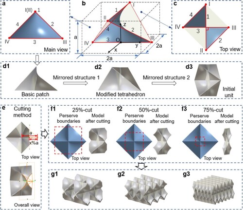
To ensure stable connections between the units, a connecting surface was created by cutting off the four edges of the initial unit in a certain proportion, where the cut-off width was expressed as a percentage of the length a (x%a, (e)). As shown in (f), the cutting directions were parallel to the XZ and YZ planes, and materials within the boundaries (red dash lines) were retained. In different designs, materials were cut in proportions of 25%, 50% and 75% to generate lattice units ((f1–f3), referred to as 25%-, 50%- and 75%-cut models hereafter), which were arrayed in the Cartesian coordinate to form the single-layered structures, respectively ((g1–g3)). Herein, the single layer referred to the layer that can be copied and stacked to make up the entire bulk structure. In this study, all the samples were modeled with the default isotropic material.
Materials and fabrication process
In this study, single-layered structures with three cutting proportions (25%, 50%, and 75%) were fabricated to study the deformation of units and the relationship between the mechanical property and relative density. For every cutting proportion, structures with different wall thickness ranging from 600 to 1400 μm were prepared in identical sizes (22.522.5
16 mm3). The single-layered structures included two modified tetrahedrons symmetrical up and down, which could show not only the internal deformation of the modified tetrahedron but also the deformation between the tetrahedron layers. To simulate the constraint at the edges of constructs in actual working conditions, plates were added at the upper and lower ends of all single-layered models, which also facilitated the clamping of samples on the testing machine. All the above models had identical unit dimensions before cutting (15
15
15 mm3 in size) and overall dimensions after assembling.
In addition, to compare the mechanical properties of the designed structures (25%-, 50%- and 75%-cut models) and several reported structures (octet-truss lattice [Citation46], Kelvin foam [Citation47], TPMS-Gyroid [Citation48] and TPMS-Primitive [Citation49]), bulk samples with the identical relative density (30%) and size (4545
45 mm3) were fabricated for analysis. Reinforcing plates in the upper and lower platens were not added in all the bulk samples, including the proposed and existing structures, to ensure that the comparison was not biased. The relative density of samples was controlled by adjusting the wall thickness of the curved surface during modeling.
Samples were manufactured using an SLA machine (SL800, ZRapid Tech, China) with acrylonitrile butadiene styrene (ABS)-like resin (BESTY-5, Kings 3D printing, China). As per the manufacturer’s instruction, the cured photosensitive resin had a density of 1.2 g/cm3, Young's modulus of 2000MPa, and Poisson's ratio of 0.4. All samples were fabricated using the same printing parameters and the same batch of base materials. After printing, the size and weight of the samples were measured using a Vernier caliper and a precision balance respectively (Figure S1). To ensure the reliability of wall thickness measurement, three different points were measured for each sample and the average value was taken.
Compression test
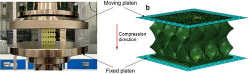
A quasi-static compression experiment was performed using a mechanical testing machine (AllroundLine Z100 SN, ZwickRoell, Germany). The specimens were fixed by two flat rigid platens, and compressed at a strain rate of 110−3s−1 ((a)). Due to the anisotropy of constructs induced by the AM process, the compression direction was consistent with the printing direction.
Figure 2. Specimens under quasi-static compression test. (a) Experimental setup. (b) Numerical model.
For the test of samples with a single layer (22.522.5
16 mm3 in size), the compression processes were terminated when samples were crushed, which was indicated by the decreased force. For the test of bulk samples with multiple layers (45
45
45 mm3 in size), the compression processes were terminated when samples reached the densification stage, at which point the force increased significantly without a visible increase of strain. For single-layered and bulk samples, preloads of 50 and 500 N were applied respectively before recording the strain data to ensure that the platens were in full contact with the sample. As there were no standards of compression testing for such ordered porous materials, the compression tests in this study were carried out based on the standards of axial compression for non-metallic and composite vertical members manufactured using extruded AM processes (ASTM-F3489 and ASTM-E2954, respectively). Three samples (n = 3) were tested and analysed for every group.
Finite element modeling
The explicit dynamics analysis using ABAQUS (Dassault, France) was conducted to display the stress distribution of the designed structures ((b)), the algorithm took time as the incremental step and did not iterate to solve nonlinear equations system, to avoid the convergence problem. The numerical model was consistent with the experimental model for the single-layered structure. Lattice structures were meshed using the solid element of C3D10M. The element is suitable for the mesh generation of complex structures while maintaining the accuracy of calculation, which was widely used in the research of mechanical metamaterials [Citation30, Citation32]. Two platens were meshed using the discrete rigid element of R3D4, which is undeformable under load. The material was modeled using an elastic-plastic constitutive model and the von Mises isotropic yield criterion (a density of 1.2 g/cm3, Young's modulus of 2000MPa, and Poisson's ratio of 0.4). The tangential contact form between the rigid platens and the lattice structure was set as a normal contact with a friction coefficient of 0.2 to avoid excessive relative sliding between the platens and structures. During analysis, the lower platen was fixed and the uniaxial compressive loading was applied by moving the upper platen downward. The deformations and contours of von Mises stress and equivalent plastic strain (PEEQ) were visualised by the built-in module of the software.
Homogenisation module of nTopology (nTopology, USA) was used to generate 3D Young’s modulus surfaces of different structures. The material properties were set to isotropic materials using the parameters described earlier, and the display mode was set to directional.
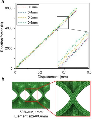
Sensitivity analysis of the mesh was carried out to determine the size of the mesh element for FEM. 50%-cut single-layered models with a wall thickness of 1 mm were meshed with different element sizes (0.3, 0.4, 0.5, and 0.6 mm), and the numerical analysis of elastic segment compression was carried out. Overall, the force values at the same displacement decreased slightly as the element size decreased, and converged when the element sizes were 0.3 and 0.4 mm ((a)). Therefore, the element size of 0.4 mm was selected for the subsequent work ((b)).
Figure 3. Sensitivity analysis of the FEM mesh. (a) Numerical force-displacement curves with various element sizes. (b) Schematic diagram of meshing.
Statistical analysis
All data were presented as the mean ± standard deviation unless stated otherwise and were analysed using one-way analysis of variance (ANOVA) to test for significance when comparing the data. Post hoc Tukey’s multiple comparison tests were used to determine the individual differences among the groups. Differences were considered significant at *p < 0.05, **p < 0.01, and ***p < 0.001. All statistical analysis was performed by Statistical Product and Service Solutions software (SPSS, IBM, USA)
Results
Geometry and assessment of samples
The structural features of three models with different cutting proportions were compared. The length of the connected portion between units in the same layer was small in the case of the 25%-cut model, and there were openings in three directions of the entire structure ((a)), revealing that the space within the structure was interconnected. For the 50%-cut model, complete connections could be achieved between units, which meant that the entire boundary of the unit contacted with that of the adjacent unit in Z direction ((g2)). Interconnected spaces were obtained only in the X and Y directions of the model, while the spaces in the Z direction were disconnected ((b)). This was because there were uncut edges on units of the 25%-cut model, and when the units were arrayed, these uncut edges were connected to form openings in the Z-axis. On the contrary, the cutting lines in 50%- and 75%-cut models intersected, therefore no opening formed (Figure S2). What’s more, a 75%-cut unit can be thought of as a 50%-cut unit with the aspect ratio increasing to twice (i.e. height: width was increased from 2: 1 to 4: 1 in this study).
Figure 4. Optical images of SLA printed models. (a-b) Top view of 25%-cut and 75%-cut models. (c-e) Images of 25%-, 50%- and 75%-cut models. (f) Top view and side view of the 50%-cut model showing the laminated striation produced in the AM process.
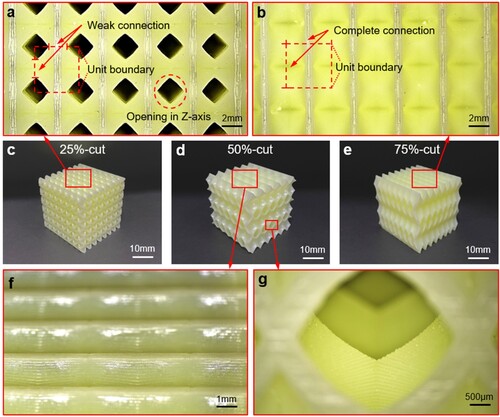
The models were manufactured by SLA ((c–e)) and their actual weights were measured, and the actual relative density was obtained by dividing the measured weight by volume (). The errors between the actual relative densities and the designed values were less than 1% for all groups, indicating reliable experimental results. The weights and relative densities of all samples were slightly larger than the designed values, which might be caused by the error in SLA printing. To avoid the influence of the anisotropy of printed samples on the compression test ((f–g)), all samples were compressed along the printing direction. Samples with different wall thickness were printed (Figure S3), and the wall thickness of designed and printed single-layered structures was consistent without significant differences ().
Table 1. Weight and relative density of SLA printed constructs (n = 3).
Table 2. Wall thickness of single-layered structures for compression test.
Deformation mechanism
FEM analysis was carried out to visualise their stress distribution under compression. In addition, the compression test of single-layered structures illustrated the deformation forms of three types of units ((d–f)). Results indicated that the deformation and failure forms in the three types of structures were different significantly, resulting from different mechanisms of stress transfer caused by connection manners among different types of units. The geometry of the three structures were different due to differences in connection manners. During the quasi-static uniaxial compression process, the sum of the forces on all sections perpendicular to the compression direction is equal to the compressive force on the structure [Citation50]. However, the damage does not always occur in the smallest section (i.e. the connection area between two layers of tetrahedral units), that’s because the damage depends not only on the magnitude of stress but also the form of stress, which is strongly related to the geometry [Citation2]. Therefore, the failure mechanism can only be obtained by observing both the stress distribution and failure form.
Figure 5. (a-c) Stress distribution of single-layered structures under compression obtained by FEM simulation (inserts: top views of stress distribution). (d-f) SLA samples after compression test.
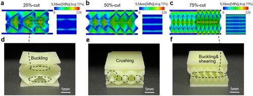
For all types of structures, the stress cloud diagrams could be divided into three parts ((a–c)), namely the low-stress area (blue colour), the high-stress area (green colour), and the stress concentration area (red colour). For the 25%-cut model, buckling occurred first at the long free edge of the unit when it was compressed ((d)), and the cracking failure happened in the stress concentration area in the middle of the unit. For the 50%-cut model, the local buckling of units was not observed due to the absence of free edges, and the failure form was material fracture ((e)). The failure mode of the 75%-cut model was mainly the buckling at the connection area between two layers of tetrahedral units ((f)), which was caused by the combination of two factors. Firstly, the stress concentration was primarily in the connection area ((c)), and secondly, the connection area in the 75%-cut model was narrower than the other two structures due to more material being cut off from edges of units.
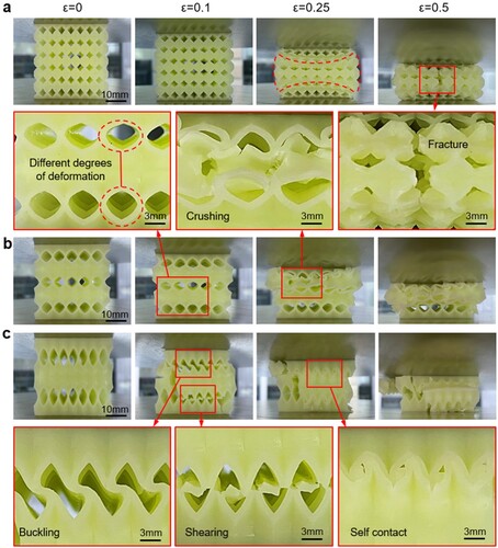
The failure modes of bulk structures were also tested and analysed (). Results showed that the compression deformation of the three structures was distinct, which attributed to the difference in stress distribution. The 25%-cut model showed uniform deformation ((a)), where every layer deformed to a similar degree with the progress of compression. However, the outermost units exhibited the smallest compression deformation due to the lack of constraints, which caused the structure to form an arc-shaped deformation. When compressed to a certain extent (∼50% strain), the fracture occurred in the middle of the structure. On the contrary, the 50%-cut model deformed unevenly and tended to collapse layer by layer ((b)). Difference in the degree of deformation between layers could be observed from the initial stage of compression, then the seriously deformed layer was crushed and fractured with the progress of compression. As shown in (c), the 75%-cut model presented a unique deformation form. The thin-walled areas buckled at first, which was indicated by the dislocation of thin walls. Next, the thin walls were sheared when the dislocation reached a critical point. As the thin walls were broken, the bulk structure fell apart into several layers, and the self-contact occurred between the concavities and convexities of adjacent layers as compression continued.
Figure 6. Optical images showing deformation details of the SLA printed structures during uniaxial compression test. (a) 25%-cut model. (b) 50%-cut model. (c) 75%-cut model. The ϵ values represented compressive strains.
Mechanical properties
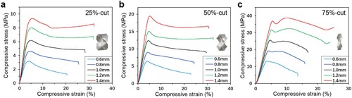
The compressive stress–strain curves of single-layered structures with different cutting proportions and wall thickness were compared (). The curves for all structures followed the characteristics of typical curves for porous materials, which started with a linear elastic phase, followed by a slight decrease after reaching the yield point and a long plateau. For all groups, slopes of the linear elastic phase and yield strength rose with the increasing wall thickness. In the plateau, the stress decreased slowly for a long period of strain, allowing for effective energy absorption. It is worth noting that curves of the 75%-cut model dropped at the yield point and then increased for a short period ((c)). Specifically, the structure buckled at the connection area between two layers of tetrahedral units after yielding, which resulted in bending of the upper and lower tetrahedral units for a short period of strain that was accompanied with the decreased stress. Next, the dislocated upper and lower tetrahedral units suffered from shearing from each other which led to the secondary stress rise.
Figure 7. Compressive stress-strain curves for three types of single-layered models with different wall thickness. (a) 25%-cut, (b) 50%-cut, and (c) 75%-cut models.
Regarding bulk structures with multiple layers and a relative density of 30%, their compressive stress–strain curves all experienced an initial linear elastic stage, and the differences appeared when structures yielded for the first time ((a)). Due to the uniform and mild compression deformation, the 25%-cut model exhibited a lengthy and mild plateau after yielding. For 50%- and 75%-cut models, the stress–strain curves fluctuated greatly after the yield point due to their non-uniform failure deformation during compression. Interestingly, a jagged fluctuation (∼10-20% strain) was observed in the curve of the 75%-cut model, which corresponded to the buckling and shearing process that was observed during the compression ((c)). When the strain reached ∼30%, contact between the crushed neighbouring layers led to sharply increased compressive stress, which was indicated by a peak on the stress–strain curve (Figure S4). The number of peaks after the yield point was equal to the number of such contacts. On the contrary, although the 50%-cut model tended to collapse layer by layer, the compressive stress–strain curve of the structure did not show multiple peaks with the same number of layers, which has been observed in Kelvin sandwich panel foam, cuttlebone-like material, and honeycomb sandwich panel foam lattices [Citation27]. This could be attributed to the fact that there was no wall between the layers to effectively block the conduction of damage.
Figure 8. (a) Stress-strain curves of different structures. (b) The Young’s modulus and energy absorption of the mechanical metamaterials (n = 3, *p < 0.05, **p < 0.01, and ***p < 0.001). (c) 3D Young’s modulus surfaces of different structures.
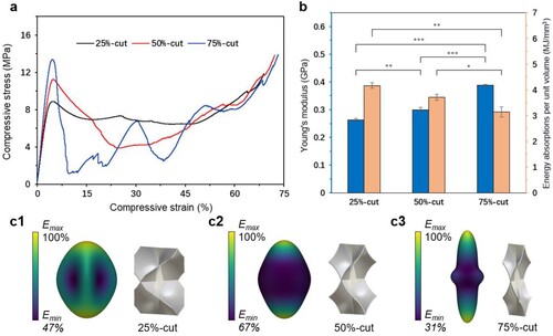
Different deformation forms also led to varied stiffness and energy absorption capacities of the three structures. Under the relative density of 30%, Young’s modulus of the 75%-cut model was the highest, followed by the 50%-cut model, and the modulus of the 25%-cut model was the lowest ((b)). This could be explained by the difference in stress distribution of different structures in the elastic stage. As shown in (a), the low-stress zone (blue colour) was the most widely distributed in the 25%-cut structure among the three structures, which implied that there was a lot of redundant material in the structure. In contrast, the proportion of the low-stress zone of the 75%-cut structure was relatively small, and hence it could withstand more pressure with the same mass.
In addition, the energy absorption per unit volume was calculated using
(2)
(2) where
is the densification strain and was taken as 60% in this study, at which point the stress showed a significant increase in all three models ((a)). Opposite to the trend of Young’s modulus, the 25%-cut model had the strongest energy absorption capacity due to its uniform deformation indicated by the relatively smooth stress–strain curve. As compared, the curve of the 75%-cut model fluctuated severely before densification, resulting in poor energy absorption capacity. The values of the 50%-cut model fell between the other two groups, exhibiting a balanced performance. On the one hand, fewer redundant materials in the structure made it stiffer than the 25%-cut model. On the other hand, most materials in the structure bore deformation during compression, which resulted in a better energy absorption capacity than the 75%-cut model.
The elastic polar plots further showed the differences in the mechanical behaviours of the three structures ((c)). 3D Young’s modulus surfaces of the three structures were all spindle-shaped with thick middle and thin ends, which implied that Young's modulus in the Z direction was the largest. It is worth noting that the 75%-cut structure with the largest Z-direction compression stiffness was the most anisotropic in elasticity and the minimum elastic modulus only accounted for 31% of the maximum value, while that of the 50%-cut structure was the least anisotropic with minimum elastic modulus accounting for 67% of the maximum value.
Overall, the 50%-cut model had the best comprehensive performance among the three structures. It had not only considerable strength and stiffness but also good compression stability and energy absorption capacity. At the same time, there was no severe damage or sudden drop of stress in the compression process.
Effect of relative density on compression performance
To investigate the changes in mechanical properties when the relative density changed, the designed structures were fitted with the Gibson-Ashby model, which built connections between the relative density and mechanical properties of porous materials. Based on this model, the normalised compressive modulus and yield stress of porous materials could be expressed as the following functions:
(3)
(3)
(4)
(4)
where Es and σs are Young’s modulus and yield strength of the material, respectively. The coefficients C and exponents n characterise the geometry of a particular unit cell. It should be noted that the exponents are more representative than the coefficients because the relationships between mechanical properties and density follow power laws [Citation32].
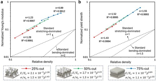
The normalised yield strength and Young’s modulus obtained by experiments were plotted versus the relative density (). The Gibson-Ashby model was used to fit the data and exponents were calculated. All R2 values approached 1, indicating good fitting outcomes. For the 25%-cut model, exponents for the normalised modulus and strength were 1.28 and 1.43, while values for the 50%-cut model were 1.23 and 1.52, respectively. For the 75%-cut model, the exponent for the strength was similar to the 50%-cut model, which was 1.55. However, the value for the modulus was 0.89 and much smaller than the other two groups. This observation revealed that the mechanical loss of the 75%-cut structure was the minimum among the three structures when the relative density was reduced. This could be attributed to the fact that the materials in the structure were mainly subjected to compressive stress instead of stretching or buckling before yielding.
Figure 9. Gibson-Ashby fittings of normalised (a) Young’s modulus and (b) yield strength with respect to relative densities (n = 3).
Comparison of mechanical properties with existing structures
To demonstrate the advantages of the proposed mechanical metamaterials, several typical porous structures were fabricated and compared, including octet-truss lattice [Citation46], Kelvin foam [Citation47], TPMS-G [Citation48] and TPMS-P [Citation49]. Among the four metamaterials, Octet-truss suffered violent fracture after yielding ((a)), while Kelvin foam, TPMS-G, and TPMS-P showed uniform deformation with the progress of compression, and the arc-shaped deformation similar to that in the 25%-cut model were observed ((b–d)). None of the four structures showed layer-by-layer collapse seen in the 50%-cut structure or obvious local buckling in the 75%-cut structure. In addition, different from the proposed structures, 3D Young’s modulus surfaces of the existing structures showed that all the four structures exhibited typical orthogonal isotropy (Figure S5).
Figure 10. Comparison of mechanical properties among proposed structures and typical mechanical metamaterials. (a–d) Compression test of SLA printed structures with (a) Octet-truss lattice, (b) Kelvin foam, (c) TPMS-G and (d) TPMS-P. (e) Stress-strain curves of different structures. (f) Young’s modulus and peak strength of seven structures (n = 3).
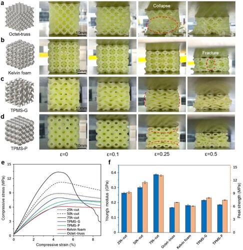
Comparing the stress–strain curves ((e)), different metamaterials had similar yield strains, which might be related to the characteristics of the printed materials. However, quantitative results showed that under the same relative density, proposed structures with three cutting proportions all exhibited superior Young’s modulus and peak strength as compared to the four typical structures in the compression direction ((f)). Specifically, for the 50%-cut structure with the best comprehensive performance, the peak strength was increased by 65% and the Young’s modulus was increased by 80% compared with the TPMS-G structure.
Discussion
In this study, a new design strategy of shell-based mechanical metamaterials has been proposed to improve the compressive load-bearing capacity of the structure without sacrificing the manufacturability. Single-layered and bulk samples were fabricated through the SLA process and the compression tests were carried out. Results showed that the strategy of designing lattice structures by refilling the tetrahedral wireframe with curved surfaces was feasible. The connected area between units could be tailored by cutting off the edges of the initial unit with different proportions, which could significantly change the mechanical performance of structures.
For different fields such as aerospace, shipbuilding, and biomedical devices, the regular application was to replace the solid materials in the parts with mechanical metamaterials, to achieve the purpose of lightweight while retaining considerable mechanical properties [Citation51]. The two major factors that affect the properties of mechanical metamaterials include structural topology and relative density [Citation5]. Due to the difference in the unit topology of lattice structures, different structures with the same wall thickness were usually not comparable [Citation28, Citation29], and hence the relative density was kept constant when comparing different structures in this study. The mechanical properties of samples manufactured by SLA process have been reported to be mostly independent with printing direction [Citation52, Citation53], thus no additional steps were taken to control the effect of anisotropy of printed samples before compressing along the printing direction. As for the FEM damage model, the deformation process of proposed structures included severe local fracture and crushing, which were different from structures with uniform compression deformation. For instance, numerical models of TPMS could provide sufficiently accurate predictions without considering material fracture or failure [Citation29]. In FEM software, the fracture mechanism was judged by the distortion ratio of mesh elements [Citation54], which makes it difficult to evaluate the breaking and crushing of materials, so the analysis of the damage model for the proposed structure could be inaccurate. Therefore, experimental compression tests were carried out on all structures to obtain the most reliable results in this study, while FEM was only used to showcase the stress distribution in the elastic segment.
There are reasons for choosing the tetrahedron as the original object for structural design. Deshpande et al. [46] have put forth the criteria for the construction of stretching-dominated structures. A sufficient condition for the deformation of a periodic structure to be stretching-dominated is that the unit cell of the structure satisfies Maxwell’s criterion for static determinacy. This criterion in three dimensions is given by the following equation:
(5)
(5) where b and j are the numbers of struts and nodes, respectively. The tetrahedral frame is the simplest unit that satisfies this condition, and the strut-based lattice structures (e.g. octet-truss) composed of tetrahedral elements often exhibit excellent performance in terms of strength and modulus [Citation31, Citation46]. Furthermore, a major advantage of the tetrahedron in structural design is that a set of opposite sides can maintain vertical or at a specific angle in space by adjusting its side lengths, which is of great significance to the arrangement of lattices and structural stability.
The pentamode metamaterials (PMMs) proposed by Milton and Cherkaev [55] were improved from a tetrahedral wireframe, and the ratio of bulk modulus B to shear modulus G (B/G) of the structure could reach 1000 [Citation13, Citation56]. The B/G of the PMMs was increased by reducing the diameter of the truss joints [Citation57], while the strength and modulus of structures in this study were increased by replacing the trusses with curved surfaces. Compared with strut-based structures with one-directional constraints, shell-based structures with two-directional constraints have greatly reduced configurational entropy and increased storage of strain energy, thereby achieving significant improvements in strength and stiffness [Citation17]. Meanwhile, the two-directional constraints of the shell-based structure led to better integrity during compression fracture instead of occurring violent fracture that was observed in the octet-truss with one-directional constraints [Citation75]. Furthermore, the stable deformation process made the structure have considerable energy absorption capacity [Citation76].
In addition, it should be noted that the cutting proportion not only affected the mechanical properties of the final structures but also the connectivity of their internal space. When the cutting proportion ≥50%, the structure had openings only in the X- and Y-axes, and when this value was <50%, the lattice had openings in all three directions (Figure 1e and S2). This property would be important when the interior of the structure was filled with a working medium such as heat transfer oil. The cutting proportion of 50% was the maximum value for the structure to have openings in only two directions, and the 25%- and 75%-cut models were chosen to represent the performance of the structure when the proportion was larger or smaller than this value. Although the mechanical properties of these three structures showed a certain trend, the specific properties of structures with other cutting proportions would need to be further studied.
In the compression test of single-layered structures, it was found that the failure mode was mainly buckling at the connection of layers for the 50%-cut model with a small wall thickness (0.6 mm), instead of the material fracture for the one with a large wall thickness (1.4 mm, Figure S6). However, significant differences in the elastic stage did not appear in the stress distribution of models with different thickness (Figure S7), demonstrating that stress distribution was not the reason for the variance in deformation form. The thin-walled cross-section between two layers of tetrahedral units could be considered a rectangle. Therefore, the change in deformation mode could be understood by the Euler’s buckling equation:
(6)
(6) where Pbuckling is the critical buckling load; E is the elastic modulus of the material; I is the area moment of inertia, which depends on the geometry of the cross-section (for rectangle,
, where b and h are the length and width of the rectangle, respectively); k is the constant depending on the degree of constraint conditions (pinned, fixed, or free); and l is the wall height. In this model, E, k, and l were quantitative, and I was a variable that changed with the wall thickness. For a model with a large wall thickness, the load required for buckling was much greater than that for a model with a smaller wall thickness. When the wall thickness of the 50%-cut model was sufficient, the limit of the material’s bearing capacity was reached earlier than the limit for buckling, so the structure fractured directly without buckling. On the contrary, the effect of wall thickness was negligible in the 75%-cut model due to its relatively large wall height (l), and buckling always occurred first.
According to the Gibson-Ashby model, for a typical stretching-dominated structure, the exponents in the fitting formulae of Young’s modulus to density and yield strength to density are both 1 [Citation46], while for a typical bending-dominated structure, these exponents are 2 and 1.5, respectively [Citation58]. The above values are all obtained through calculations of ideal models. In practice, structural topology is the most important factor affecting the exponent values [Citation59]. In addition, the combination of stretching and bending deformation is usually present when an object is compressed, which affects the exponent values. Also, since it is difficult to ensure all materials in the structure bear the deformation during compression, the exponent in the fitting equation is likely to be larger than the abovementioned values. Furthermore, manufacturing and testing methods affect the fitting to some extent. For example, the residual stress in the structure made the compressive stress lower than the predicted value when samples were manufactured SLM and EBM [Citation5]. Relative density can also be miscalculated due to measurement errors [Citation59]. Although these factors make the model parameters different from the theoretical values, the fundamental insight is widely acknowledged that there is a positive power relationship between the properties of a lattice structure and its relative density, and hence the model is regularly introduced into the study of AM lattice structure [Citation2]. In general, exponents are small when the structure deformation is mainly dominated by stretching or compression, which results in excellent mechanical performance.
In this study, the designed structures exhibited small exponents, and the mechanical performance overtook that of most TPMS structures and strut-based structures [Citation31, Citation28, Citation32, Citation29]. For example, the corresponding exponents (for Young’s modulus and yield strength) of stretching-dominated octet-truss (made of aluminum oxide) were 1.61 and 1.76, respectively [Citation31], and the popular cuttlebone-like structure that aimed to enhance the load-bearing capacity had an exponent for the strength of 1.8 [Citation27], which were all greater than the exponents of our designed structures. Hence, it could be concluded that the pre-yield mechanical properties of the three structures in this study have been significantly improved compared to reported structures, evidenced by the low exponent values.
The mechanical theory of porous solids recognises that porous structures possess high strength only when they have a stretching-dominated deformation [Citation46, Citation58]. In the comparison of various structures, it was found that the mechanical properties of stretching-dominated octet-truss were weaker than those of TPMS structures composed of sheets. As for TPMS, although gyroid and primitive structures utilised bending-dominated deformation to obtain superior stability in the compression process [Citation29], the stiffness and strength were quite limited. In comparison, the proposed structures in this study realised the compression/stretching-dominated deformation taking advantage of the incorporated curved surface, which greatly improved the compression performance. What’s more, the balance between the compressive strength and structural stability of structures could be obtained by varying the cutting proportions of tetrahedral units, to meet requirements of different applications. For instance, the 75%-cut structure could achieve more than 1.8 times the compressive strength of the octet-truss ((f)), while the integrity of the structure still maintained during compression, without catastrophic failure compared to the octet-truss (c and a). For the 25%-cut model with superior compression stability, its strength and modulus were also higher than the four reported structures. Besides, structural efficiency-anisotropy is one of the major considerations to balance various competing mechanical properties in the design of advanced metamaterials, and anisotropic structures tend to be weaker than isotropic ones in a particular direction [Citation2]. However, according to the results of 3D Young’s modulus surfaces and compression test, Young’s modulus of the 50%-cut structure in the weakest direction (67% of that in the compression direction) was still larger than all four existing structures (e.g. 20% higher than the gyroid structure).
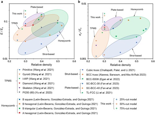
The Ashby charts showed the uniaxial compression performance of different structures further demonstrating the superiority of the proposed structures [Citation64–Citation67, Citation72, Citation73, Citation77–Citation78] (). The comparisons of Young's modulus and yield strength were determined by the experimental results, and all data were normalised according to Young's modulus of the base material. It should be pointed out that the manufacturing and testing methods used in different works have a great impact on the experimental results, the normalisation could only reduce these differences to a certain extent. The coloured areas in the Ashby charts showed the compression performance of different types of structures [Citation60, Citation61]. The stiffness and strength of proposed structures were superior over other structures with the identical relative density, and even better than most of those with higher relative density.
Figure 11. Comparison of the normalised Young’s modulus and yield strength of the proposed metamaterials with others.
As for future directions, more mechanical properties of proposed structures except the compression properties are worthy of investigation, including the deformation under the shear, torsion or combined loads. In addition, functional mechanical metamaterials with superior sound absorption, heat exchange, and other properties over simple load-bearing materials have drawn more and more attention [Citation62]. In this regard, the proposed structures include spatial separation, which is the basis for the design of cross-flow heat exchangers [Citation37]. For sound absorption applications, the complex connected spaces inside the TPMS structure make it difficult to work as a Helmholtz resonator [Citation63], while the structure units in this study only need to be modified slightly to achieve this function.
Additionally, it is worth noting that the proposed structures could be fabricated using metallic AM techniques such as selective laser melting and electron beam melting, which would be promising for applications requiring enhanced mechanical properties.
Conclusions
Herein, a new design method was applied to generate mechanical metamaterials. The tetrahedral wireframe was refilled with curved surfaces, followed by mirroring the modified tetrahedron to create the initial unit. The units were then cut with specific proportions and arrayed to form different structures. The compression properties of the structure could be adjusted by changing the cutting proportion of edges. Single-layered and bulk samples of the proposed structure were fabricated through the SLA process. The compression tests and finite element analysis were carried out. The conclusions are listed below:
The strategy of designing lattice structures by retaining the tetrahedral wireframe and refilling it with curved surfaces was feasible, through which the manufacturability could be improved by eliminating the internal cavity of structures, and the considerable mechanical properties could be retained.
Results of the compression test demonstrated that the 25%-cut model had the best compression stability and energy absorption capacity among the proposed structures, and the 75%-cut model had the highest modulus and strength. It was also observed that the new structures exhibited superior compression properties over several reported structures (e.g. strength increased by 65% and Young’s modulus increased by 80%, respectively, compared with the TPMS-G structure).
Gibson-Ashby fittings showed that the proposed mechanical metamaterials had small power law exponents (e.g. E∝
1.23 and σ∝
By adjusting the cutting proportion, the geometry of the structure was controllable, and thus the proposed structures had the potential to be applied in the development of functional metamaterials.
Taken together, these findings demonstrated that the lightweight mechanical metamaterials designed by refilling tetrahedral wireframes were capable of effectively undertaking the load-bearing task and had advantages over some existing structures, implying its potential applications in aerospace, shipbuilding, and biomedical devices.
Disclosure statement
No potential conflict of interest was reported by the author(s).
Data availability statement
All data that support the findings of this study are included in the article.
Additional information
Funding
References
- Chua C, Leong Sing S, Chua CK. Characterisation of In-situ alloyed titanium-tantalum lattice structures by laser powder Bed fusion using finite element analysis. Virtual Phys Prototyp. 2023;18(1):e2138463.
- Wu, Wenwang, Re Xia, Guian Qian, Zengqian Liu, Nima Razavi, Filippo Berto, and Huajian Gao. 2023. “Mechanostructures: rational mechanical design, fabrication, performance evaluation, and industrial application of advanced structures.” Prog Mater Sci 131 (January): 101021.
- Mao A, Chen J, Bu X, et al. Bamboo-Inspired structurally efficient materials with a large continuous gradient. Small. 2023: 2301144.
- Zheng X, Lee H, Weisgraber TH, et al. Ultralight, ultrastiff mechanical metamaterials. Science. 2014;344(6190):1373–1377.
- Chen L-Y, Liang S-X, Liu Y, et al. Additive manufacturing of metallic lattice structures: unconstrained design, accurate fabrication, fascinated performances, and challenges. Mater Sci Eng: R Rep. 2021;146(October):100648.
- Santoni S, Gugliandolo SG, Sponchioni M, et al. 3D bioprinting: current status and trends—a guide to the literature and industrial practice. Bio-Des Manuf. 2022;5(1):14–42.
- Sefene EM. State-of-the-Art of selective laser melting process. J Manuf Syst. 2022;63(April):250–274.
- Sun Y, Gao Z, Zhang X, et al. 3D-Printed, Bi-Layer, biomimetic artificial periosteum for boosting bone regeneration. Bio-Des Manuf. 2022;5(3):540–555.
- Ajdari A, Nayeb-Hashemi H, Vaziri A. Dynamic crushing and energy absorption of regular, irregular and functionally graded cellular structures. Int J Solids Struct. 2011;48(3):506–516.
- Heinl P, Müller L, Körner C, et al. Cellular Ti–6Al–4 V structures with interconnected macro porosity for bone implants fabricated by selective electron beam melting. Acta Biomater. 2008;4(5):1536–1544.
- Garner E, Kolken HMA, Wang CCL, et al. Compatibility in microstructural optimization for additive manufacturing. Addit Manuf. 2019;26(March):65–75.
- Ma L, Yang H. Bio-Manufacturing innovation lights up the future. Bio-Des Manuf. 2023;6(2):204–215.
- Schittny R, Bückmann T, Kadic M, et al. Elastic measurements on macroscopic three-dimensional pentamode metamaterials. Appl Phys Lett. 2013;103(23):231905.
- Li, Sheng, Hany Hassanin, Moataz M. Attallah, Nicholas J.E. Adkins, and Khamis Essa. 2016. “The development of TiNi-based negative poisson’s ratio structure using selective laser melting.” Acta Mater 105 (February): 75–83.
- Han, Seung Chul, Jeong Woo Lee, and Kiju Kang. 2015. “A New type of Low density material: shellular.” Adv Mater 27 (37): 5506–5511.
- Schaedler TA, Jacobsen AJ, Torrents A, et al. Ultralight metallic microlattices. Science. 2011;334(6058):962–965.
- Berger JB, Wadley HNG, McMeeking RM. Mechanical metamaterials at the theoretical limit of isotropic elastic stiffness. Nature. 2017;543(7646).
- Yue C, Zhao W, Li F, et al. Shape recovery properties and load-carrying capacity of a 4D printed thick-walled kirigami-inspired honeycomb structure. Bio-Des Manuf. 2023;6(2):189–203.
- Yang, Xiao, Qin Yang, Yunsong Shi, Lei Yang, Siqi Wu, Chunze Yan, and Yusheng Shi. 2022. “Effect of volume fraction and unit cell size on manufacturability and compressive behaviors of Ni-Ti triply periodic minimal surface lattices.” Addit Manuf54 (June): 102737.
- Kelly CN, Francovich J, Julmi S, et al. Fatigue behavior of As-built selective laser melted titanium scaffolds with sheet-based gyroid microarchitecture for bone tissue engineering. Acta Biomater. 2019;94(August):610–626.
- Yin J, Qian J, Huang Y. Physics problems in Bio or bioinspired additive manufacturing. Bio-Des Manuf. 2023;6(2):99–102.
- Yang Y, Song X, Li X, et al. Recent progress in biomimetic additive manufacturing technology: from materials to functional structures. Adv Mater. 2018;30(36):1706539.
- Wei K, Chen H, Pei Y, et al. Planar lattices with tailorable coefficient of thermal expansion and high stiffness based on dual-material triangle unit. J Mech Phys Solids. 2016;86(January):173–191.
- Wei K, Peng Y, Qu Z, et al. A cellular metastructure incorporating coupled negative thermal expansion and negative poisson’s ratio. Int J Solids Struct. 2018;150(October):255–267.
- Han L, Che S. An overview of materials with triply periodic minimal surfaces and related geometry: from biological structures to self-assembled systems. Adv Mater. 2018;30(17):1705708.
- Ashby MF, Gibson LJ. Cellular solids: structure and properties. Cambridge: Press Syndicate of the University of Cambridge; 1997.
- Mao A, Zhao N, Liang Y, et al. Mechanically efficient cellular materials inspired by cuttlebone. Adv Mater. 2021;33(15):2007348.
- Al-Ketan O, Rowshan R, Al-Rub RKA. Topology-Mechanical property relationship of 3D printed strut, skeletal, and sheet based periodic metallic cellular materials. Addit Manuf. 2018;19(January):167–183.
- Qiu N, Wan Y, Shen Y, et al. Experimental and numerical studies on mechanical properties of TPMS structures. Int J Mech Sci. 2023;July:108657.
- Chen R, Wang S, Wu Z, et al. Compressive enhancement gyroid lattice with implicit modeling implementation and modified G-A model property prediction. Mater Des. 2023;232(August):112153.
- Meza LR, Das S, Greer JR. Strong, lightweight, and recoverable three-dimensional ceramic nanolattices. Science. 2014;345(6202):1322–1326.
- Guo X, Ding J, Li X, et al. Enhancement in the mechanical behaviour of a schwarz primitive periodic minimal surface lattice structure design. Int J Mech Sci. 2022;216(February):106977.
- Tan J, Li J, Ran Z, et al. Accelerated fracture healing by osteogenic Ti45Nb implants through the PI3K–Akt signaling pathway. Bio-Des Manuf. 2023;6(6):718–734.
- Li Y, Ding Y, Munir K, et al. Novel β-Ti35Zr28Nb alloy scaffolds manufactured using selective laser melting for bone implant applications. Acta Biomater. 2019;87(March):273–284.
- Jin Y, Zou S, Pan B, et al. Biomechanical properties of cylindrical and twisted triply periodic minimal surface scaffolds fabricated by laser powder Bed fusion. Addit Manuf. 2022;56(August):102899.
- Yoo D. New paradigms in hierarchical porous scaffold design for tissue engineering. Mater Sci Eng: C. 2013;33(3):1759–1772.
- Liang D, Shi C, Li W, et al. Design, flow characteristics and performance evaluation of bioinspired heat exchangers based on triply periodic minimal surfaces. Int J Heat Mass Transfer. 2023;201(February):123620.
- Wang X, Gao T, Shi C, et al. Effect of geometric configuration on compression behavior of 3D-printed polymeric triply periodic minimal surface sheets. Mech Adv Mater Struct. 2023;30(11):2304–2314.
- Wang, Zhonggang, Xinxin Wang, Tianyu Gao, and Chong Shi. 2021. “Mechanical behavior and deformation mechanism of triply periodic minimal surface sheet under compressive loading.” Mech Adv Mater Struct 28 (19). 2057–2069.
- Gao T, Liu K, Wang X, et al. Multi-Level mechanism of biomimetic TPMS hybridizations with tailorable global homogeneity and heterogeneity. Extreme Mech Lett. 2024;68(May):102136.
- Plocher J, Panesar A. Mechanical performance of additively manufactured fiber-reinforced functionally graded lattices. JOM. 2020;72(3):1292–1298.
- Al-Ketan, Oraib, Dong-Wook Lee, Reza Rowshan, and Rashid K. Abu Al-Rub. 2020. “Functionally graded and multi-morphology sheet TPMS lattices: design, manufacturing, and mechanical properties.” J Mech Behav Biomed Mater 102 (February): 103520.
- Ejeh, Chukwugozie J., Imad Barsoum, Aliaa M. Abou-Ali, and Rashid K. Abu Al-Rub. 2023. “Combining multiple lattice-topology functional grading strategies for enhancing the dynamic compressive behavior of TPMS-based metamaterials.” J Mater Res Technol 27 (November): 6076–6093.
- Tancogne-Dejean T, Diamantopoulou M, Gorji MB, et al. 3D Plate-Lattices: An emerging class of Low-density metamaterial exhibiting optimal isotropic stiffness. Adv Mater. 2018;30(45):1803334.
- Yang T, Jia Z, Chen H, et al. Mechanical design of the highly porous cuttlebone: A bioceramic hard buoyancy tank for cuttlefish. Proc Natl Acad Sci USA. 2020;117(38):23450–23459.
- Deshpande VS, Fleck NA, Ashby MF. Effective properties of the octet-truss lattice material. J Mech Phys Solids. 2001;49(8):1747–1769.
- Warren WE, Kraynik AM. Linear elastic behavior of a Low-density kelvin foam with open cells. J Appl Mech. 1997;64(4):787–794.
- Abueidda DW, Elhebeary M, (Andrew) Shiang C-S, et al. Mechanical properties of 3D printed polymeric gyroid cellular structures: experimental and finite element study. Mater Des. 2019;165(March):107597.
- Lee D-W, Khan KA, Al-Rub RKA. Stiffness and yield strength of architectured foams based on the schwarz primitive triply periodic minimal surface. Int J Plast. 2017;95(August):1–20.
- Taleff, Eric M., and Roy R. Craig. 2020. Mechanics of materials, 4th Edition. Wiley Press.
- Nazir, Aamer, Kalayu Mekonen Abate, Ajeet Kumar, and Jeng-Ywan Jeng. 2019. “A state-of-the-Art review on types, design, optimization, and additive manufacturing of cellular structures.” Int J Adv Manuf Tech 104 (9): 3489–3510.
- Manière C, Kerbart G, Harnois C, et al. Modeling sintering anisotropy in ceramic stereolithography of silica. Acta Mater. 2020;182(January):163–171.
- Aravind Shanmugasundaram, Sunil, Jafar Razmi, Md Jamal Mian, and Leila Ladani. 2020. “Mechanical anisotropy and surface roughness in additively manufactured parts fabricated by stereolithography (SLA) using statistical analysis.” Materials (Basel) 13 (11). 2496.
- Khennane, Amar. 2013. Introduction to finite element analysis using MATLAB® and abaqus. CRC Press.
- Milton GW, Cherkaev AV. Which elasticity tensors Are realizable? J Eng Mater Technol. 1995;117(4):483–493.
- Kadic M, Bückmann T, Stenger N, et al. On the practicability of pentamode mechanical metamaterials. Appl Phys Lett. 2012;100(19):191901.
- A. Zadpoor A. Mechanical meta-materials. Mater Horiz. 2016;3(5):371–381.
- Deshpande VS, Ashby MF, Fleck NA. Foam topology: bending versus stretching dominated architectures. Acta Mater. 2001;49(6):1035–1040.
- Maconachie T, Leary M, Lozanovski B, et al. SLM lattice structures: properties, performance, applications and challenges. Mater Des. 2019;183(December):108137.
- Almesmari A, Barsoum I, Al-Rub RKA. Modelling, optimization, and testing of novel cuboidal spherical plate lattice structures. Virtual Phys Prototyp. 2024;19(1):e2308514.
- Almesmari A, Baghous N, Ejeh CJ, et al. Review of additively manufactured polymeric metamaterials: design, fabrication, testing and modeling. Polymers (Basel). 2023;15(19):3858.
- Jiao, Pengcheng, Jochen Mueller, Jordan R. Raney, Xiaoyu (Rayne) Zheng, and Amir H. Alavi. 2023. “Mechanical metamaterials and beyond.” Nat Commun 14 (1). 6004.
- Li X, Wei Chua J, Yu X, et al. 3D-Printed lattice structures for sound absorption: current progress, mechanisms and models, structural-property relationships, and future outlook. Adv Sci. 2024;11(4):2305232.
- Alawwa, Fares, Imad Barsoum, and Rashid K. Abu Al-Rub. 2023. “Modeling, testing, and optimization of novel lattice structures for enhanced mechanical performance.” Mech Adv Mater Struct: 1–24.
- Challapalli A, Patel D, Li G. Inverse machine learning framework for optimizing lightweight metamaterials. Mater Des. 2021;208(October):109937.
- Egan, Paul F., Nava Raj Khatri, Manasi Anil Parab, and Amit M. E. Arefin. 2022. “Mechanics of 3D-printed polymer lattices with varied design and processing strategies.” Polymers (Basel) 14 (24). 5515.
- Fan, Bingbing, Zhisun Xu, Yongshui Lin, and Zhixin Huang. 2023. “Mechanical properties of a novel Two-phase hybrid plate-lattice metamaterial.” Mech Adv Mater Struct 30 (23). 4752–4763.
- Gao S, Ding J, Qu S, et al. Numerical and experimental investigation of additively manufactured shell-lattice copper heat exchanger. Int Commun Heat Mass Transfer. 2023a;147(October):106976.
- Gao T, Liu K, Wang X, et al. Elastic wave manipulation via functional incorporation of Air-solid phases in hybrid TPMS. Compos Commun. 2023b;44(December):101745.
- Gao T, Liu K, Wang X, et al. Elastic mechanical property hybridization of configuration-varying TPMS with geometric continuity. Mater Des. 2022a;221(September):110995.
- Gao Z, Wang H, Sun H, et al. Additively manufactured high-energy-absorption metamaterials with artificially engineered distribution of bio-inspired hierarchical microstructures. Compos B Eng. 2022b;247(December):110345.
- León-Becerra, Juan, Octavio A. González-Estrada, and Jabid Quiroga. 2021. “Effect of relative density in In-plane mechanical properties of common 3D-printed polylactic acid lattice structures.” ACS Omega 6 (44). 29830–29838.
- Li, Tiantian, Firas Jarrar, Rashid Abu Al-Rub, and Wesley Cantwell. 2021. “Additive manufactured semi-plate lattice materials with high stiffness, strength and toughness.” Int J Solids Struct 230–231 (November): 111153.
- Li X, Wang H, Sun L, et al. 3D chiral energy-absorbing structures with a high deformation recovery ratio fabricated via selective laser melting of the NiTi alloy. ACS Appl Mater Interfaces. 2023a;November.
- Li Z, Li X, Wang X, et al. Interpenetrating hollow microlattice metamaterial enables efficient sound-absorptive and deformation-recoverable capabilities. ACS Appl Mater Interfaces. 2023b;15(20):24868–24879.
- Li Z, Li X, Wang Z, et al. Multifunctional sound-absorbing and mechanical metamaterials via a decoupled mechanism design approach. Mater Horiz. 2023c;10(1):75–87.
- Sokollu B, Gulcan O, Konukseven EI. Mechanical properties comparison of strut-based and triply periodic minimal surface lattice structures produced by electron beam melting. Addit Manuf. 2022;60(December):103199.
- Yu A, Zhang C, Xu W, et al. Additive manufacturing of multi-morphology graded titanium scaffolds for bone implant applications. J Mater Sci Technol. 2023;139(March):47–58.