
 ?Mathematical formulae have been encoded as MathML and are displayed in this HTML version using MathJax in order to improve their display. Uncheck the box to turn MathJax off. This feature requires Javascript. Click on a formula to zoom.
ABSTRACT
Screw-based material extrusion 3D printing technology offers the potential for manufacturing fibre-reinforced composites with component gradients by mixing materials within the printhead. However, mixing composites with high fibre content sufficiently in a limited range for rapid component switching presented a challenge. Herein, an in-situ variable component screw-based printhead was developed. Pins with different geometries were added to 8, 12, and 16 mm diameter extrusion screws, to enhance the mixing efficiency. A particle tracking model based on computational fluid dynamics simulations was used to optimise the geometry and distribution of pins by taking 0-40 wt% short carbon fibre-reinforced polyether-ether-ketone (SCF/PEEK) as an example. The incorporation of pins enhanced the mixing efficiency but aggravated the dead zone, which decreased the variable component response rate. An optimal design of pins that balanced mixing efficiency and response rate was developed, by which the variable component response rate was promoted by 369%, while the degree of mixing was improved by 50%. Benefitting from the enhanced mixing, the tensile strength of in-situ mixed 20 wt% SCF/PEEK composites was increased by 23%. The in-situ variable component screw-based extrusion printhead developed and optimised in this investigation provided a novel approach to fabricating fibre-reinforced composites with variable components.
1. Introduction
Composites with continuous compositional gradients exhibit superior mechanical performances [Citation1] and locally tailored versatile properties [Citation2] compared to homogenous materials, but are difficult to be fabricated using traditional machining processes. 3D printing allows for precise control over the spatial distribution of materials at the scale of an individual volumetric pixel [Citation3], showing new perspectives for the integrated design and fabrication of functionally graded materials. The 3D printing technologies capable of controlling material components in different regions of the same part were defined as ‘variable component 3D printing’, including direct ink writing [Citation4,Citation5], stereolithography [Citation6,Citation7], aerosol jet printing [Citation8], etc. However, the existing technologies faced the problems of limited material selections and complex component control methods.
Screw-based material extrusion 3D printing technology can offer an in-situ mixing of two or more materials within the printhead through a rotating extrusion screw [Citation9], which has demonstrated great versatility with a wide variety of materials [Citation10–13]. Fibre-reinforced composites are gaining great importance due to their low density, excellent mechanical properties, and broader design space [Citation14–16]. However, to the best knowledge of the authors, the 3D printing technology of fibre-reinforced composites with variable components has not been developed. In previous studies, Lu et al. [Citation17] reported a screw-based material extrusion 3D printing system, by which SCF/PEEK composites with up to 50 wt% fibre content were successfully manufactured. Although screw-based material extrusion 3D printing technology had tremendous potential for composites with variable components, it faced the challenge of sufficiently mixing composites in a short range to realise a fast response to component variations. Therefore, the printhead must be rationally designed to meet two performance requirements: high mixing efficiency and a fast variable component response rate.
The extrusion screw is the core part of the screw-based extrusion printhead, but standard screws of extruders [Citation12,Citation13] or a tool for CNC machines [Citation18] were typically used due to the complexity of screw design and fabrication, making it difficult to achieve adequate mixing within the limited space of the printhead. Additionally, the switching speed of material components would be slowed down due to the dead volume caused by the regions with low flow velocity [Citation9]. To address both issues, the structure of the screw was optimised by researchers. Ober et al. [Citation11] used a 2.7 mm diameter reamer with multiple asymmetric grooves along the axial direction to enhance mixing and designed a low ratio of length to diameter (L/D) of the reamer to reduce the dead volume. Sinha et al. [Citation10] designed a triangular thread-cutting profile of the screw to minimise the dead volume and found that the mixing capacities of triangular and square thread-cutting profiles were comparable using a particle tracking model (screw diameter 6 mm, total length 41 mm). Mi et al. [Citation19] designed a screw with shear elements (screw diameter 16 mm, total length 240 mm), which improved the mixing efficiency and stability of printing compared to a conventional single screw. However, there were two shortcomings in current studies that prevent the realisation of 3D printing for fibre-reinforced composites with variable components. On the one hand, in current screw-based multi-material 3D printing systems, the raw materials typically included several thermoplastic materials and liquid inks, but the challenges posed by fibre fillers, such as uneven fibre dispersion [Citation20] and clogging of the printhead caused by the dramatical increase in apparent material viscosity and fibre agglomeration [Citation21], remain unresolved. On the other hand, the design parameters of the screw have not been optimised aiming at high mixing efficiency and a fast variable component response rate.
The objective of this research is to develop an in-situ mixing screw-based material extrusion 3D printhead for composites with variable components. Incorporating pins in screw channels in a single screw extruder to promote mixing was a common practice in polymer extrusion [Citation22]. Inspired by this, pins with different geometries were added on the surface of the extrusion screws with diameters of 8, 12, and 16 mm. The geometries and distribution of the pins were optimised using computational fluid dynamics (CFD) simulations by taking 0-40 wt% short carbon fibre-reinforced polyether-ether-ketone (SCF/PEEK) as an example. In-situ mixing 3D printing experiments and tension tests were conducted to evaluate the mechanical properties. Variable component 3D printing and greyscale calibration experiments were performed to characterise the rates of component variations. The in-situ mixing screw-based material extrusion 3D printing method established in this investigation would provide a new way to fabricate composites with continuous component gradients.
2. Materials and methods
2.1. Extrusion screw design and optimisation
2.1.1. In-situ variable component 3D printhead for composites
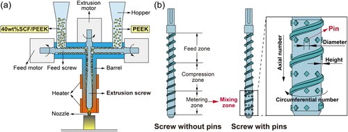
A screw-based material extrusion 3D printhead capable of controlling material components was self-developed, and the schematic diagram is illustrated in (a). 40 wt% short carbon fibre-reinforced polyether-ether-ketone (SCF/PEEK) and pure PEEK powders were fed into the printhead from two sides, respectively, and were melted, mixed, and extruded through a rotating extrusion screw. Parts with continuously varying carbon fibre content could be produced by adjusting the speed ratio of the feed screws during the printing process.
Figure 1. Variable component printhead and extrusion screw. (a) Schematic of the variable component printhead in sectional view to show the internal structure. (b) Structures of the extrusion screw without and with pins (40 wt% SCF/PEEK: 40 wt% short carbon fibre-reinforced polyether-ether-ketone).
2.1.2. Extrusion screw design
The extrusion screw was the key part of the screw-based extrusion 3D printhead, which conveys, melts, and extrudes materials while providing an in-situ mixing through rotating in a barrel. The screw typically had three zones: feed zone, compression zone, and metering zone. The metering zone was modified to a mixing zone with evenly distributed pins to promote the mixing efficiency, as shown in (b). The screw was designed as 8, 12, and 16 mm diameters with geometric parameters shown in Table S1. The clearance between the screw and barrel was 0.1 mm. The geometry and distribution parameters of the pins included shape (S), diameter (D), height (H), axial number (Na), and circumferential number (Nc), with design optional values shown in .
Table 1. Optional values of the pin geometric parameters.
2.1.3. Optimisation of the geometry and distribution of pins
CFD simulations using Ansys Polyflow (2020 R2 version, ANSYS Inc., U.S.) were employed to investigate the effect of the design of the pins on the mixing and dead volume. To simplify the computational model, only the molten flow in the mixing zone was considered. The mesh superposition technique (MST) was used to model the 3D flow with a rotational boundary. A generalised Newtonian isothermal model was used to calculate the fluid velocity, with the boundary conditions set as Fig. S3(a) and Table S2. The materials were set to 0-40 wt% SCF/PEEK considering component variations. The viscosity followed the Carreau–Yasuda law (Eq. (S1)), and rheological parameters were set according to our previous study [Citation17], as shown in Table S3. A steady-state solution was calculated. After solving for the flow, a particle tracing model was solved using the calculated flows to drive the motion of particles. Randomly distributed 1000 particles were released in half of the inlet and tracked, as shown in Fig. S3(b). The distribution index was used to quantify the mixing effect [Citation23], which indicated the difference between the actual particle distribution and a uniform distribution. To eliminate the effect of the particle distribution at the inlet of each calculation, the degree of mixing (d) was defined as the negative relative change of the distribution index at the outlet compared to that at the inlet, as shown in Equation (1):
(1)
(1) where δi is the distribution index at the inlet and δo is the distribution index at the outlet. The degree of mixing was determined as the average of three calculations. Optimal pin parameters were selected based on orthogonal experimental results to achieve a good mixing for 0-40 wt% SCF/PEEK (see Table S4-S6). The dead volume was defined as the volume of fluids with a flow rate less than 50% of the maximum rate in the mixing zone.
2.2. Experimental verification
2.2.1. Equipment and material
The printing experiments were based on the in-situ variable component 3D printer for composites, as shown in Fig. S1. The optimised screws were fabricated by Laser Powder Bed Fusion (LPBF) with stainless steels and polished carefully to achieve a good surface finish (Ra≈1.6), as shown in Fig. S2. In this study, PEEK powders (150 P, VICTREX Co., Ltd., UK) were chosen as the matrix material. Short carbon fibres (SCF, HST40-12k, TOHO, Japan) were chosen as the reinforcing material with a length of around 100 µm. 2, 5, 10, 20, 30, and 40 wt% SCF/PEEK powders were prepared by mechanical mixing at 100 rpm for 4 h using a high-speed mixer (HC-229, Shandong Hongchao Machinery Equipment Co., Ltd., Shandong, China). Before mixing, the SCF and PEEK powders were dried at 150°C for four hours to eliminate moisture.
2.2.2. In-situ mixing 3D printing of 20 wt% SCF/PEEK
The previous study indicated that 20 wt% SCF/PEEK composites had relatively good tensile strength and toughness [Citation17]. Thus, 20 wt% SCF/PEEK composites were mixed in situ and printed using the optimal screws. 40 wt% SCF/PEEK and pure PEEK powders were fed into the printhead from two sides in a 1:1 ratio. The temperatures of the compression zone and the mixing zone were set to 380 and 400 °C, respectively, allowing SCF/PEEK composites to be fully melted, mixed, and extruded with good flowability but not be thermally deteriorated [Citation24]. Other process parameters were set according to the previous study: nozzle diameter 1 mm, line width 0.8 mm, layer thickness 0.2 mm, and printing speed 30 mm/s [Citation17]. The printing direction was along the long side of the samples. The ambient temperature was controlled at 25 °C during the whole printing process.
Tensile tests (n = 5) were performed following ISO 527 standard, using a universal testing machine (PLD-5, Xi’an Lichuang Material Testing Technology Co., Ltd., China) equipped with a 30 kN force transducer, under a displacement rate of 2 mm/min.
To reveal the tensile fracture morphologies of the samples, the cross-sections of the fractured specimens were characterised with a scanning electron microscopy (SEM, EVO10, Carl Zeiss Co., Ltd., Germany).
To evaluate the porosity of the in-situ mixed samples, the apparent density of the samples was measured with a digital balance (HM-G02, Shandong Hengmei Electronic Technology Co., Ltd., China) based on the principles of Archimedes. The porosity of the samples (p) was characterised by the relative density, calculated by Equation (2):
(2)
(2) where ρ is the apparent density of the samples, and ρ0 is the theoretical density of the samples.
2.2.3. In-situ variable component 3D printing
Samples with variable material components from PEEK to 20 wt% SCF/PEEK were prepared as shown in (a). The printing process involved printing the pre-stored PEEK in the printhead, in-situ mixed 20 wt% SCF/PEEK, and pure PEEK. To account for the different volumes of the printheads with the 12 and 16 mm diameter screws, the total heights of the pre-stored PEEK section were set to 10 and 20 mm, respectively. To ensure a complete transition from 20 wt% SCF/PEEK to PEEK, the heights of the final PEEK section were set to 30 and 50 mm for the 12 and 16 mm diameter screws, respectively, for more materials stagnated with the 16 mm diameter screw. The process parameters remained the same as those for the in-situ mixing 3D printing.
Figure 2. Designed variable component samples and fitted relationship between the greyscale and carbon fibre content. (a) Designed variable component samples for the 12 and 16 mm diameter screws. (b) Greyscale calibration samples and the fitted relationship between the greyscale and carbon fibre content.
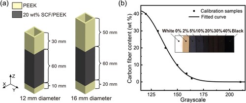
Greyscale calibration samples were prepared using pure PEEK and pre-mixed 2, 5, 10, 20, 30, and 40 wt% SCF/PEEK, and photographed using a high-resolution camera (EOS200D II, Canon Inc., U.S.). A relationship between the greyscale and the carbon fibre content was established by the average grayscales of the samples, as illustrated in (b).
The switching speed between different components of the printhead was evaluated using the variable component response rate (v), defined by Equation (3):
(3)
(3) where ΔwCF is the change in carbon fibre content and ΔV is the minimum volume required to change from the initial content to the target content within a 5% error. The variable component response rate consisted of two cases: the response rate of carbon fibres changing from low to high content, denoted as vlh, and the response rate of carbon fibres changing from high to low content, denoted as vhl.
3. Results
3.1. Degree of mixing and dead volume
The degrees of mixing (DOM) for the 8, 12, and 16 mm diameter screws with different pins for 0-40 wt% SCF/PEEK are shown in Table S7-S9, respectively. For each screw diameter and pin geometry, the worst DOM of SCF/PEEK composites with CF content from 0 to 40 wt% was selected as an indicator to evaluate the influence of the pin design on mixing efficiency. The optimal pin parameters were determined as shown in . As depicted in (a), the worst DOM for the screws without pins occurred as the carbon fibre content increased to 40 wt%, whereas the screws with the optimal pins exhibited a better mixture for all components. The 12 mm diameter screw with diamond pins enhanced the worst DOM by 50% compared to the screw without pins, promoting the mixing significantly. However, the pins increased the dead volume meanwhile, as shown in (b).
Figure 3. Degree of mixing and dead volume of the 8, 12, and 16 mm diameter screws. (a)-(c) Degree of mixing. (d)-(f) Dead volume.
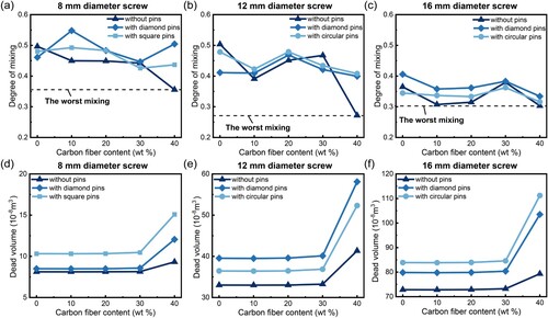
Table 2. Optimal pin parameters of the 8, 12, and 16 mm diameter screws.
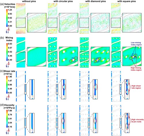
shows the fluid’s velocity, mixing index [Citation25] (elongational flow ratio), shear rate, and viscosity for the 12 mm diameter screws without and with the optimal pins. It was found that the fluid moved as laminar flow in the helical direction for the screw without pins, while high mixing index only occurred around the flights. When the pins were inserted, higher mixing index regions occurred around the pins, whereas a few low mixing index regions were observed at the pin’s vertexes. There were some high-shear rate regions between the pins and barrel. The dead volume was found at the roots of the flights and pins with high viscosity.
Figure 4. Velocity, mixing index, shear rate, and viscosity of the fluid with the 12 mm diameter screw without pins, with circular pins, with diamond pins, and with square pins for 40 wt% SCF/PEEK. (a) Velocity vector. (b) Mixing index. (c) Shear rate. (d) Viscosity.
3.2. Mechanical properties
The tensile strength and elongation at break of the in-situ mixed 20 wt% SCF/PEEK samples using the 12, 16 mm diameter screws are shown in (a) and (b). The results of the 8 mm diameter screws were not obtained due to the discontinuous extrusion with bubbles. One-way significance analyses were performed for the results of the 12, 16 mm diameter screws, respectively. It was found that the 12 mm diameter screw with diamond pins exhibited the highest improvement in mechanical properties, increasing the tensile strength and elongation at break by 23.4% and 59.7%, respectively.
Figure 5. Mechanical properties of the samples printed by the 12, 16 mm diameter screws (significant differences marked as *: p < 0.05; **: p < 0.01; ***: p < 0.001) and SEM pictures of the tensile fracture surface of samples printed by the 12 mm diameter screw without pins and with diamond pins. (a) Tensile strength. (b) Elongation at break. (c) Uneven fibre distribution in the samples printed by the 12 mm diameter screw without pins (yellow circles marking fibres). (d) Uniform fibre distribution in the samples printed by the 12 mm diameter screw with diamond pins.
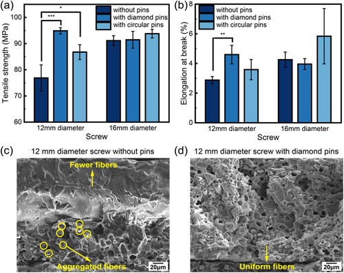
The SEM pictures within one printed layer of the in-situ mixed samples were observed. Some regions with uneven fibre distribution were found in the samples printed by the 12 mm diameter screw without pins, with aggregated fibres on one side and almost pure PEEK on the other side, as shown in (c). In contrast, the sample printed by the screw with pins showed a uniform fibre distribution, as shown in (d).
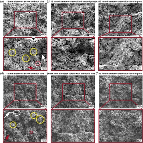
The tensile fracture morphologies are shown in . Fibre aggregations occurred in the fracture surfaces of the 12, 16 mm diameter screws without pins ((a), (d)). The pins led to a more uniform fibre distribution in the matrix ((b), (c), (e), (f)). Defects were observed in the specimens, including interline pores, fibre pull-out holes, interlayer gaps, and air pores.
Figure 6. Tensile fracture morphologies of the samples using the 12, 16 mm diameter screws (yellow circles marking fibre aggregations; white circles marking interline pores; red circles marking fibre pull-out holes; white arrows marking interlayer gaps; red arrows marking air pores).
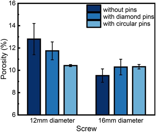
The porosity of the samples was distributed around 10%, as shown in . One-way significance analyses were performed for the results of the 12, 16 mm diameter screws, respectively. There was no significant difference in porosity.
Figure 7. Porosity of the samples using the 12, 16 mm diameter screws.
3.3. Variable component response rate
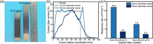
The 12 mm diameter screw with diamond pins and the 16 mm diameter screw with circular pins exhibited the best improvement in mechanical properties. Therefore, these screws were selected to conduct the in-situ variable component 3D printing, and the printed samples are shown in (a). (b) shows the fibre content variations with different Z-axis relative coordinates. The relative coordinates originated at the point where PEEK began to transit to 20 wt% SCF/PEEK. It was found that the actual component change was a lagging continuous process rather than an abrupt process as designed. Note that there was a fluctuation in the curve of the 12 mm diameter screw when the Z-axis relative coordinate was about 60 mm, which was due to the decrease in the extrusion volume caused by the change of feeding material (from 20 wt% SCF/PEEK to PEEK). The actual content should be the red dotted line drawn in the figure. The variable component response rates are demonstrated in (c). The vlh (from 0 to 20 wt% CF) of the 12 mm diameter screw was 4.7 times higher than that of the 16 mm diameter screw, while the vhl (from 20 to 0 wt% CF) of the 12 mm diameter screw was 3.5 times higher than that of the 16 mm diameter screw. Therefore, the printhead with the 12 mm diameter screw exhibited a faster variable component response.
Figure 8. Results of the in-situ variable component 3D printing. (a) Variable component samples of the 12 and 16 mm diameter screws. (b) Carbon fibre content variations with different Z-axis relative coordinates. (c) Variable component response rates of the 12 and 16 mm diameter screws.
In summary, the 8 mm diameter screw was unable to print stably. The 16 mm diameter screw had low mixing efficiency and a slow variable component response rate. In comparison, the 12 mm diameter screw with diamond pins demonstrated a better and more stable mixing and a faster variable component response rate, making it the optimal structure for the extrusion screw.
4. Discussion
There was a lack of manufacturing methods for fibre-reinforced composites with component gradients that had significant potential for engineering applications. Screw-based material extrusion 3D printing technology has enabled various multi-material in-situ mixing production, making it a feasible way to prepare fibre-reinforced composites with varying components. However, sufficient mixing of composites with a high fibre filler content in a short range to realise a fast response to component variations posed a challenge. In this study, an in-situ variable component printhead using an extrusion screw with mixing pins was developed. The geometries and distribution of the pins were optimised based on CFD simulations by taking 0-40 wt% SCF/PEEK as an example. Mechanical properties of the in-situ mixed 20 wt% SCF/PEEK composites and the response rate from 0 to 20 wt% CF were characterised. The results showed that the 12 mm diameter screw with diamond pins improved the degree of mixing by 50% and the variable component response rate by 369%. The in-situ mixing printhead opened a new way to fabricate fibre-reinforced composites with controllable gradient components.
To achieve efficient mixing, diamond, square, and circular pins were added to the extrusion screw with diameters of 8, 12, and 16 mm. The mixing capacities of the screws with and without pins were investigated by a particle tracing model. The worst DOF occurred as the CF content increased up to 40 wt% for the screws without pins, which was attributed to the inefficient diffusion-dependent mixing in laminar flow for high-viscosity fluids [Citation5]. In comparison, the inserted pins showed a better mixing for all components, which was probably due to introducing a large number of reorientations for the fluid by pins [Citation26]. The high mixing index regions were observed around the pins where the fluid elements were stretched violently, indicating the generation of chaotic mixing which was an effective way to promote the mixing of fluids with a low Reynolds number [Citation27]. Additionally, the tight spaces between the pins and barrel generated high shear rates, which helped to break aggregates and reduced the viscosity through shear thinning, leading to better mixing. Thus, the mixing efficiency could be significantly improved by adding the pins to the extrusion screw.
Considering both the strength and toughness of the SCF/PEEK composites, 20 wt% SCF/PEEK composites were mixed in situ and printed with the 8, 12, and 16 mm diameter screws with the optimised pins. The printhead with the 8 mm diameter screw could not print stably, probably due to a poor transport capacity resulting from a small screw channel depth. The 12 mm diameter screw with diamond pins exhibited the highest improvement in mechanical properties. This may be ascribed to a homogeneous dispersion of CFs that could be observed in the tensile fracture morphologies. It has been confirmed that the maximum mechanical properties of composites could be achieved when fibres were uniformly distributed in the matrix [Citation28,Citation29]. However, it was hard to fulfil the homogeneity requirement for fabrication due to the tendency of fibre aggregation [Citation29], especially when the fibre filler content was high [Citation30], which limited the improvement of mechanical performances [Citation17]. Therefore, the homogeneous dispersion of the fibres could be promoted through stirring and high shearing by the pins, leading to higher mechanical properties.
The mechanical properties of 20 wt% SCF/PEEK composites manufactured by screw-based material extrusion 3D printing (S-MEX) were compared with those by fused filament fabrication (FFF) [Citation31] and injection molding (IM) [Citation32], as shown in . The mechanical properties in this study still had a gap compared to other mature technologies. This might be explained by high porosity, poor interlayer bonding, low crystallinity, and short fibre length. The in-situ mixed samples prepared in this study exhibited a relatively high porosity of around 10%, which may be attributed to non-optimised process parameters during printing. Compared to molding or fused filament fabrication 3D printing, the in-situ mixing process of PEEK and SCF in the printhead was more likely to introduce air voids, which might be the reason for the higher porosity. By optimising the process parameters, the porosity is expected to be significantly reduced [Citation17], as in our previous study on screw-based materials extrusion, the porosity of in-situ mixed 20 wt% SCF/PEEK was reduced to 2.48% by reducing the ratio of the extrusion speed to the material feed speed. In this study, the ambient temperature was controlled at around 25°C, which could result in fast cooling rates, leading to poorer interlayer bonding [Citation33] and lower crystallinity [Citation24]. In addition, fibres with a short length of around 100 μm were used, limiting mechanical property enhancement. To enhance the mechanical properties, several measures will be taken in the subsequent work, including optimisation of printing parameters, using a heating chamber, increasing fibre length, and annealing treatments. Previous studies showed that the tensile strength of in-situ mixed 20 wt% SCF/PEEK composites can be increased to 169.8 MPa by increasing the fibre length to 209 μm and annealing treatments [Citation34].
Figure 9. Comparison of the mechanical properties of 20 wt% SCF/PEEK composites using screw-based material extrusion 3D printing (S-MEX), fused filament fabrication (FFF), and injection molding (IM) [Citation31,Citation32].
![Figure 9. Comparison of the mechanical properties of 20 wt% SCF/PEEK composites using screw-based material extrusion 3D printing (S-MEX), fused filament fabrication (FFF), and injection molding (IM) [Citation31,Citation32].](/cms/asset/501c9a6e-d528-443d-b26f-cbe37904d997/nvpp_a_2366517_f0009_oc.jpg)
Screw-based extrusion 3D printing technology can control component gradients at the level of volumetric pixels by adjusting the in-situ mixing ratio of materials during the printing process. However, the variable component response rate of the printhead was limited by the dead volume [Citation10] resulting from flow stagnation zones [Citation35], which was directly related to three factors: the material, pins, and screw diameter. According to the simulation results, the dead volume was increased by 16% as the carbon fiber content was increased to 40 wt%, due to a considerable rise in material viscosity. The dead volume also could be increased by 10%−34% by the introduction of the pins, which can be ascribed to the low-velocity and high-viscosity regions at the roots of the pins. In addition to the material and pins. the dead volume was found to be proportional to the third power of the screw diameter, corresponding to the volume of the printhead. Thus, designing a small-diameter screw with reasonable geometries and distribution of the pins was essential for controlling the dead volume.
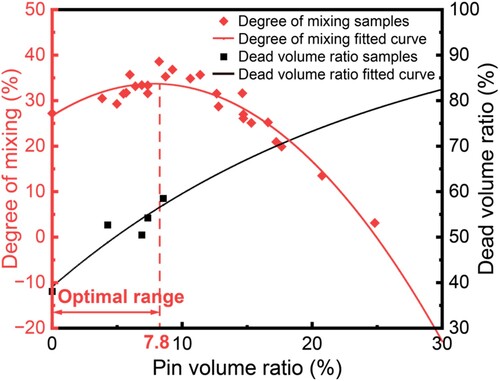
The geometries and distribution of the pins could influence both the degree of mixing and dead volume. It was found that the effect of the pin shape on the DOM was not significant. Therefore, the pin volume was selected as the indicator to combine the geometric parameters of the pins apart from the shape. To eliminate the effect of the screw diameter, the pin volume and dead volume were normalised by the volume of the fluid in the mixing zone. The fitted curves of the worst DOF for 0–40 wt% SCF/PEEK and dead volume for 40 wt% SCF/PEEK with pin volume ratios are shown in . The worst DOF kept going up to the maximum when the pin volume ratio was about 7.8%. This can be explained as introducing more fluid reorientations and high-mixing index regions. However, the mixing became worse when the pin volume ratio was over 7.8%, due to the increase in the dead volume ratio. Material agglomeration at the roots of the pins led to poor mix efficiency overall. Therefore, there was an optimal range of the pin volume ratio considering both the mixing capacity and variable component response rate: between 0 and 7.8%.
Figure 10. Degree of mixing and dead volume ratio with different pin volume ratios.
There are several limitations and future perspectives in this study. Firstly, in the simulation of the mixing process, the commonly used Lagrangian particle tracking model [Citation23] was selected without considering the aspect ratio of CFs, interactions between CFs, and interactions between CFs and the matrix, which might lead to the deviation of the simulation results from the experimental results. Secondly, given the unavoidable hysteresis of switching the component, it can be compensated for by designing a feeding strategy. For instance, increase the change of components to speed up the variable component response rate, which will be investigated in the future. Thirdly, in response to the dissatisfied mechanical properties, careful process optimisation, including printing parameters [Citation33], fibre pretreatment [Citation36], longer fibres [Citation34], and post-treatment [Citation17,Citation37], will be considered in future work. Particularly, adaptive controlling of process parameters during component variations will be a key focus of future development.
Composites with component gradients could be successfully manufactured by the in-situ mixing screw-based material extrusion 3D printhead and could be used in a wide variety of potential applications, including bioengineering [Citation38], soft robotics [Citation39], and aerospace [Citation40]. Additionally, it will promote the emergence of new design strategies differing from the design of conventional homogeneous materials, to achieve new properties and functionalities by designing compositional variation in a part [Citation3].
5. Conclusions
In this study, an in-situ mixing 3D printhead for SCF/PEEK composites with variable components was designed and optimised, opening a new way to fabricate composites with continuous component gradients. The following conclusions can be drawn from the results:
An in-situ variable component printhead based on an extrusion screw with mixing pins was developed. The geometry and distribution of the pins were optimised using CFD simulations by taking 0–40 wt% SCF/PEEK as an example, and the worst degree of mixing was improved by 50% compared to a screw without pins.
The dead volume that resulted in hysteresis during material switching was increased by 10%−34% because of the pins due to the low-velocity and high-viscosity regions at the pin roots. Thus, the pin volume ratio within the range of 0–7.8% was found to be the optimal region.
The tensile strength and elongation at break were increased by 23% and 60% by the 12 mm diameter screw with diamond pins, respectively, compared to the screw without pins, and the variable component response rate was promoted by 369%, compared to the 16 mm diameter screw.
Supplemental Material
Download MS Word (19 MB)Disclosure statement
No potential conflict of interest was reported by the author(s).
Data availability statement
Data will be available upon request from the authors.
References
- Liu Z, Meyers MA, Zhang Z, et al. Functional gradients and heterogeneities in biological materials: design principles, functions, and bioinspired applications. Prog Mater Sci. 2017;88:467–498. doi:10.1016/j.pmatsci.2017.04.013
- Li Y, Feng Z, Hao L, et al. A review on functionally graded materials and structures via additive manufacturing: from multi-scale design to versatile functional properties. Adv Mater Technol. 2020;5:1900981. doi:10.1002/admt.201900981
- Mirzaali MJ, Herranz De La Nava A, Gunashekar D, et al. Mechanics of bioinspired functionally graded soft-hard composites made by multi-material 3D printing. Compos Struct. 2020;237:111867. doi:10.1016/j.compstruct.2020.111867
- Pelz JS, Ku N, Shoulders WT, et al. Multi-material additive manufacturing of functionally graded carbide ceramics via active, in-line mixing. Addit Manuf. 2021;37:101647. doi:10.1016/j.addma.2020.101647
- Hassan I, Selvaganapathy PR. A microfluidic printhead with integrated hybrid mixing by sequential injection for multimaterial 3D printing. Addit Manuf. 2022;50:102559. doi:10.1016/j.addma.2021.102559
- Zhong L, Du J, Xi Y, et al. Multi-material and parameter-controllable stereolithography 3D printing of graded permittivity composites for high voltage insulators. Virtual Phys Prototyp. 2023;18:e2271447. doi:10.1080/17452759.2023.2271447
- Valizadeh I, Al Aboud A, Dörsam E, et al. Tailoring of functionally graded hyperelastic materials via grayscale mask stereolithography 3D printing. Addit Manuf. 2021;47:102108. doi:10.1016/j.addma.2021.102108
- Zeng M, Du Y, Jiang Q, et al. High-throughput printing of combinatorial materials from aerosols. Nature. 2023;617:292–298. doi:10.1038/s41586-023-05898-9
- Justino Netto JM, Idogava HT, Frezzatto Santos LE, et al. Screw-assisted 3D printing with granulated materials: a systematic review. Int J Adv Manuf Technol. 2021;115:2711–2727. doi:10.1007/s00170-021-07365-z
- Sinha R, Cámara-Torres M, Scopece P, et al. A hybrid additive manufacturing platform to create bulk and surface composition gradients on scaffolds for tissue regeneration. Nat Commun. 2021;12:500. doi:10.1038/s41467-020-20865-y
- Ober TJ, Foresti D, Lewis JA. Active mixing of complex fluids at the microscale. Proc Natl Acad Sci U.S.A. 2015;112:12293–12298. doi:10.1073/pnas.1509224112
- Zhou Z, Salaoru I, Morris P, et al. Additive manufacturing of heat-sensitive polymer melt using a pellet-fed material extrusion. Addit Manuf. 2018;24:552–559. doi:10.1016/j.addma.2018.10.040
- Ren L, Song Z, Liu H, et al. 3D printing of materials with spatially non-linearly varying properties. Mater Des. 2018;156:470–479. doi:10.1016/j.matdes.2018.07.012
- Wang W, Gao X, Zhang L, et al. Large-scale material extrusion-based additive manufacturing of short carbon fibre-reinforced silicon carbide ceramic matrix composite preforms. Virtual Phys Prototyp. 2023;18:e2245801. doi:10.1080/17452759.2023.2245801
- Wong J, Altassan A, Rosen DW. Additive manufacturing of fiber-reinforced polymer composites: A technical review and status of design methodologies. Compos Part B: Eng. 2023;255:110603. doi:10.1016/j.compositesb.2023.110603
- van de Werken N, Tekinalp H, Khanbolouki P, et al. Additively manufactured carbon fiber-reinforced composites: state of the art and perspective. Addit Manuf. 2020;31:100962. doi:10.1016/j.addma.2019.100962
- Lu S, Zhang B, Niu J, et al. Effect of fiber content on mechanical properties of carbon fiber-reinforced polyether-ether-ketone composites prepared using screw extrusion-based online mixing 3D printing. Addit Manuf. 2024;80:103976. doi:10.1016/j.addma.2024.103976
- Kumar N, Jain PK, Tandon P, et al. The effect of process parameters on tensile behavior of 3D printed flexible parts of ethylene vinyl acetate (EVA). J Manuf Process. 2018;35:317–326. doi:10.1016/j.jmapro.2018.08.013
- Mi D, Zhang J, Zhou X, et al. Direct 3D printing of recycled PET/PP granules by shear screw extrusion. Polymers. 2023;15:4620. doi:10.3390/polym15244620
- Li G, Qu Y, Yang Y, et al. Effect of mechanical combined with electromagnetic stirring on the dispersity of carbon fibers in the aluminum matrix. Sci Rep. 2020;10:8106. doi:10.1038/s41598-020-64983-5
- Croom BP, Abbott A, Kemp JW, et al. Mechanics of nozzle clogging during direct ink writing of fiber-reinforced composites. Addit Manuf. 2021;37:101701. doi:10.1016/j.addma.2020.101701
- Kimura K, Nakayama Y, Kajiwara T. Distributive mixing characteristics of a Dulmage-type screw for a single-screw extruder: experimental and numerical evaluation. Chem Eng J Adv. 2021;7:100137. doi:10.1016/j.ceja.2021.100137
- Wong TH, Manas-Zloczower I. Two-dimensional dynamic study of the distributive mixing in an internal mixer. Int Polym Process. 1994;9:3–10. doi:10.3139/217.940003
- Yang C, Tian X, Li D, et al. Influence of thermal processing conditions in 3D printing on the crystallinity and mechanical properties of PEEK material. J Mater Process Technol. 2017;248:1–7. doi:10.1016/j.jmatprotec.2017.04.027
- Yang HH, Manas-Zloczower I. 3D flow field analysis of a Banbury mixer. Int Polym Process. 1992;7:195–203. doi:10.3139/217.920195
- Stroock AD, Dertinger SKW, Ajdari A, et al. Chaotic mixer for microchannels. Science. 2002;295:647–651. doi:10.1126/science.1066238
- Jana SC, Tjahjadi M, Ottino JM. Chaotic mixing of viscous fluids by periodic changes in geometry: baffled cavity flow. AIChE J. 1994;40:1769–1781. doi:10.1002/aic.690401102
- Sharma R, Kar KK, Das MK, et al. Short carbon fiber-reinforced polycarbonate composites. In: KK Kar, editor. Composite materials: processing, applications, characterizations. Berlin, Heidelberg: Springer; 2017. p. 199–221. doi:10.1007/978-3-662-49514-8_6
- Rao Y-N, Dai H-L, Dai T, et al. Linkages among fiber content, porosity and local aggregation in fiber-reinforced composites, and their effect on effective properties. J Mater Sci. 2017;52:12486–12505. doi:10.1007/s10853-017-1344-7
- Fallon JJ, McKnight SH, Bortner MJ. Highly loaded fiber filled polymers for material extrusion: A review of current understanding. Addit Manuf. 2019;30:100810. doi:10.1016/j.addma.2019.100810
- Carbon-PEEK-Technical-datasheet-ENG-01.pdf. n.d.. cited 2024 May 21 https://plastigen.cl/wp-content/uploads/2024/03/Carbon-PEEK-Technical-datasheet-ENG-01.pdf.
- Chang B, Gu J, Long Z, et al. Effects of temperature and fiber orientation on the tensile behavior of short carbon fiber reinforced PEEK composites. Polym Compos. 2021;42:597–607. doi:10.1002/pc.25850
- Rendas P, Figueiredo L, Geraldo M, et al. Improvement of tensile and flexural properties of 3D printed PEEK through the increase of interfacial adhesion. J Manuf Process. 2023;93:260–274. doi:10.1016/j.jmapro.2023.03.024
- Lu S, Zhang B, Niu J, et al. High-strength carbon fiber-reinforced polyether-ether-ketone composites with longer fiber retention length manufactured via screw extrusion-based 3D printing. Addit Manuf. 2024;86:104200. doi:10.1016/j.addma.2024.104200
- Ortega JM, Golobic M, Sain JD, et al. Active mixing of disparate inks for multimaterial 3D printing. Adv Mater Technol. 2019;4:1800717. doi:10.1002/admt.201800717
- Ma Z, Pu Y, Huang Y, et al. Improvement in interface and mechanical properties of CF/poly(ether-imide) and CF/poly(ether-ether-ketone) by aqueous sizing of reactive cationic poly(amide-imide) with catechol pendant groups on CF. Compos Sci Technol. 2022;230:109754. doi:10.1016/j.compscitech.2022.109754
- Yu X, Song W, Zheng J, et al. Effects of Low-pressure annealing on the performance of 3D printed CF/PEEK composites. Chin J Mech Eng: Addit Manuf Front. 2023;2:100076. doi:10.1016/j.cjmeam.2023.100076
- Lowen JM, Leach JK. Functionally graded biomaterials for use as model systems and replacement tissues. Adv Funct Mater. 2020;30:1909089. doi:10.1002/adfm.201909089
- Cho SY, Ho DH, Jo SB, et al. Direct 4D printing of functionally graded hydrogel networks for biodegradable, untethered, and multimorphic soft robots. IJEM. 2024;6:025002. doi:10.1088/2631-7990/ad1574
- Saleh B, Jiang J, Fathi R, et al. 30 years of functionally graded materials: An overview of manufacturing methods. Appl Future Challenges, Compos Part B: Eng. 2020;201:108376. doi:10.1016/j.compositesb.2020.108376