
 ?Mathematical formulae have been encoded as MathML and are displayed in this HTML version using MathJax in order to improve their display. Uncheck the box to turn MathJax off. This feature requires Javascript. Click on a formula to zoom.
ABSTRACT
Precisely controlling the distribution of continuous fibres on a cylindrical surface is crucial for manufacturing high-performance continuous fibre-reinforced composite (CFRC) tubular structures. Existing manufacturing processes are complex, hindering the regulation of fibre orientation and content. Therefore, this study achieved unrestricted control of 3D-printed continuous fibres in terms of content and arbitrary orientation on a cylindrical surface using a cylindrical layered path planning strategy. The study investigated the impact of different fibre orientations and printing parameters on the compressive performance and energy absorption of 3D-printed CFRC tubes under quasi-static axial compression by analysing fibre distribution and failure modes. Compared to the flat layered printing strategy, the cylindrical layered printing strategy showed significant increases in compressive strength and energy absorption, by 44.3% and 85.2%, respectively. A cusp height analysis model demonstrated that the cylindrical layered printing strategy significantly enhances forming accuracy compared to the conventional flat layered method. The CFRC lightweight energy absorption tubes fabricated with this strategy demonstrated the viability of the manufacturing process. This new manufacturing technology has significant potential for producing high-performance and high-precision CFRC energy absorption tubes, applicable in aeronautics and astronautics.
1. Introduction
Continuous fibre-reinforced composites (CFRCs) have emerged as an essential material in the field of manufacturing due to their outstanding mechanical performance [Citation1], efficient energy absorption properties [Citation2], and light weight [Citation3]. As a typical crashworthy structure, continuous fibre-reinforced composite (CFRC) energy absorption tubes effectively absorb a large amount of energy with fibre and resin fractures, separation, delamination, and so on [Citation4–6]. Therefore, energy absorption tubes are progressively gaining prominence in load-bearing and energy-absorption structural applications in aerospace, high-speed railways, ships, and other industries [Citation7–9].
Fibre distribution plays a crucial role in influencing the performance of CFRC energy absorption tubes. Supian [Citation10], Hu [Citation11], and Wang [Citation12] investigated the failure modes and energy absorption capability of CFRC energy absorption tubes with different fibre orientations under compression, demonstrating that fibre orientation had a significant influence on the compression performance of energy absorption tubes. Additionally, these studies have suggested that selecting a suitable fibre orientation can improve the energy absorption capability of CFRC energy absorption tubes. Alia [Citation13], Mohd [Citation14], and Xu [Citation15] focused on the influence of the fibre content on the energy absorption capability of CFRC energy absorption tubes. They found that increasing the fibre content could enhance the compression performance of CFRC energy absorption tubes. Furthermore, the configuration of fibre arrangement, such as a honeycomb structure, can significantly enhance the energy absorption properties of energy absorption tubes.
Thus far, various manufacturing techniques for CFRC energy absorption tubes have been developed to facilitate the distribution of continuous fibres on the cylinder surface. Traditional manufacturing methods include hot pressing [Citation16], fibre winding [Citation17], pultrusion [Citation18], and vacuum-assisted resin infusion [Citation19]. However, these processes possess some limitations to effectively fabricate energy absorption tubes. These processes are incapable of achieving continuous fibre in arbitrary orientations or correctly controlling fibre content [Citation20]. Furthermore, the complexity of manufacturing processes and high-precision of specific shapes restrict the utilisation of CFRC energy absorption tubes, especially for tubes with different fibre configurations [Citation21,Citation22]. Therefore, developing a new manufacturing technique that can effectively control fibre distribution is essential to fabricate high-performance CFRC energy absorption tubes.
Recently, 3D printing of CFRCs with fused deposition modelling has rapidly advanced as a novel manufacturing method [Citation23–25]. The manufacturing process involves integrating fibres and resin, subjected to accumulation moulding along a predetermined printing path to achieve rapid production [Citation26]. The method boasts benefits such as low costs, a rapid production cycle, and excellent automation [Citation27–29]. It also can precisely regulate fibre content [Citation30] and orientation [Citation31,Citation32]. Therefore, 3D printing provides a new approach for the cost-effective and expedited production of high-performance CFRC energy absorption tubes. Tian et al. [Citation33] examined the interface and performance of 3D-printed continuous fibre-reinforced composites, successfully fabricating cylinders and wings. Paolo et al. [Citation34] manufactured circular, rectangular, and T-section beams as well as other structures using 3D-printed continuous fibre-reinforced composites. They measured the impregnation quality and mechanical properties of fibres and PLA. The above research studies validated the feasibility of 3D-printed CFRC energy absorption tubes and controlling fibre content.
Additionally, Shi et al. [Citation35] explored the designable strength and reinforcement orientation of 3D-printed continuous fibre composites by changing various fibre layer distributions and fibre orientations. Kong et al. [Citation36] explored mechanical responses and failure of 3D-printed continuous carbon fibre composites by using different materials and different fibre angles as variables. Morales et al. [Citation37] analysed the axial and radial crushing behaviour of the thin-walled structures with different cross-section geometry employing longitudinal and concentric fibre orientations. These studies collectively confirmed that 3D printing continuous fibre technology can control the fibre orientation. Furthermore, other studies have demonstrated that 3D-printed continuous fibre-reinforced composites technology can fabricate produce various fibre configurations, such as honeycomb [Citation38], lattice [Citation39], sandwich [Citation40], diamond [Citation41] and more.
However, the CFRC energy absorption tubes discussed in above studies were fabricated with a flat layered 3D printing strategy, resulting in fibres being distributed only along the circumference of the tubes. This limitation prevented the precise regulation of continuous fibre distribution on the cylinder surface, which hindered the full realisation of the reinforcing effect of continuous fibres on energy absorption. It is impossible to precisely regulate the distribution of continuous fibres on a cylinder surface according to the characteristics of CFRC energy absorption tubes. Consequently, the reinforcing effect of continuous fibres on energy absorption has yet to be fully realised. Therefore, a novel 3D printing strategy is imperative to address this issue.
In this research, a cylindrical layered 3D printing strategy was used for the rapid manufacturing of high-performance CFRC energy absorption tubes to control over fibre distribution on a cylindrical surface. The impact of various fibre orientations and printing parameters on the performance and the failure modes of the energy absorption tubes under axial compression was investigated. The interrelationships between the printing parameters, fibre distribution, and failure modes were discussed. The parameters influencing the forming accuracy of 3D printed CFRC energy absorption tubes were analysed by establishing the cusp height analysis model. A comparison was made between the performance and accuracy of CFRC energy absorption tubes with cylindrical layered and flat layered printing strategies. To confirm the precise control of fibre distribution on the cylindrical surface, a lightweight energy absorption tube was manufactured using the cylindrical layered 3D printing strategy.
2. Experimental procedures
2.1. 3D printing method and materials
2.1.1. Cylindrical layered 3D printing process planning
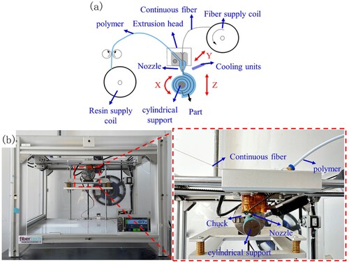
This paper proposes a cylindrical layered 3D printing strategy to achieve the controllable distribution of continuous fibres on a cylinder surface. As shown in (a), the composite was formed by simultaneously melting thermoplastic resin and impregnating reinforced fibres in the extrusion head. Subsequently, the composite was extruded from the nozzle. After cooling and curing, the composite was adhered to the cylindrical support and fixed in place with a chuck. The nozzle had linear motion along the axis of the cylindrical support, while the cylindrical support had rotational motion, facilitating the accurate distribution of continuous fibres on the cylinder surface.
Figure 1. Principle and equipment of 3D printing for CFRC energy absorption tubes, (a) Scheme of the printing process, (b) Equipment for the 3D printing of CFRC energy absorption tubes.
The printing path plays a crucial role in determining fibre orientation and content, thereby affecting the performance of CFRC energy absorption tubes. To fully leverage the benefits of continuous fibres and precisely control fibre distribution on the cylinder surface, the cylindrical layered 3D printing path planning strategy was employed in this research to fabricate CFRC energy absorption tubes. First, the layer thickness (h) was given to divide the model of energy absorption tubes into equal-thickness cylindrical layers, and the cylindrical layer radius (Ri) can be calculated by the following formula:
(1)
(1) where r is the radius of the cylindrical support, i is the layer number which starts from 1.
For the sake of convenience in subsequent calculations, the centre point of each cylindrical layer was aligned with the origin of the three-dimensional Cartesian coordinate system (Cxyz). Subsequently, a distinct single-pass printing path was developed for every cylindrical layer to ensure uninterrupted continuity of fibre bundles throughout the entire printing procedure. As shown in , the printing paths on the cylindrical layer are divided into three types. The first printing path is planned along the axis of the cylinder (θ = 0°). The second printing path is planned along the helix of the cylinder (0° < θ < 90°). The third printing path is planned along the circular curve (θ = 90°). To simplify the printing path planning, the cylindrical surface is initially flattened into a plane, and the three-dimensional Cartesian coordinate system (Cxyz) convert to the Plane coordinate system (Pxy). Subsequently, the printing path is planned on the plane using the parallel line filling method. Finally, the plane is transformed back into the cylindrical surface, completing the printing path planning for the cylindrical layer.
Figure 2. 3D printing path planning for the cylindrical layer.
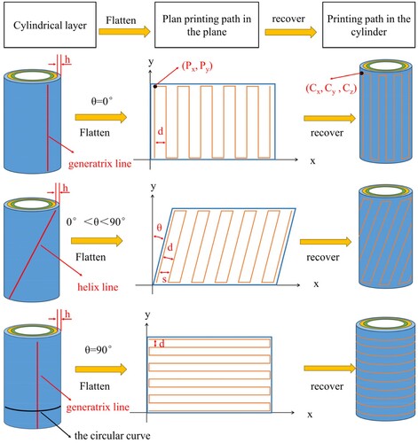
When the printing path is planned along the axis of the cylinder (θ = 0°), the cylindrical surface is flattened into a rectangular plane along the generatrix line of the cylinder, and the parametric equation for the generatrix line is as follows:
(2)
(2) Then, on the rectangular plane, fill it with parallel lines perpendicular to the X-axis with a horizontal distance of the hatch spacing (d) between each parallel line.
When the printing path is planned along the helix line of the cylinder (0°<θ<90°), the cylindrical surface is flattened into a parallelogram plane along the helical path, and the parametric equation for the helical path is as follows:
(3)
(3) where δ is a parameter.
Subsequently fill the parallelogram plane with parallel lines at an angle θ to the Y-axis, with a horizontal distance of s between each parallel line. S can be calculated using Equation (4):
(4)
(4) When the printing path is planned along the circular curve (θ = 90°), the cylindrical surface is flattened into a rectangular plane along the generatrix line of the cylinder using Equation (2). Then fill the rectangular plane with parallel lines perpendicular to the Y-axis, with a vertical distance of the hatch spacing (d) between each parallel line.
After completing the path planning on the plane, plane coordinates are transformed to the three-dimensional coordinates using the following formulas:
(5)
(5)
(6)
(6)
(7)
(7)
Finally, the printing path can be transformed from three-dimensional Cartesian coordinates system (Cxyz) to the machining coordinate system (Mxyz) rotated about the Y-axis using the following formulas:
(8)
(8)
(9)
(9)
(10)
(10)
2.1.2. Materials and equipment
In this study, printing equipment ((b)) that was modified from the Education version COMBOT-I of Shaanxi Fibertech Technology Development Co., Ltd. for the fabrication of the CFRC energy absorption tubes was adopted.
The reinforcement material was continuous Kevlar fibre (with a linear density of 145 dtex and a density of 1440 kg/m3) from DuPont Corp, and the matrix material was PLA (1.75 mm, 1240 kg/m3) from Flashforge Corp. in China.
2.2. Mechanical evaluations
2.2.1. Experimental plan
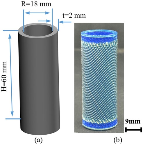
Two key factors, fibre orientation (θ) and hatching spacing (d), significantly impact the mechanical performance energy absorption capability of 3D-printed CFRC energy absorption tubes. To investigate the effect of fibre orientation on the performance of 3D-printed CFRC energy absorption tubes, tubes were prepared and tested at fibre orientations of 0°, 22.5°, 45°, 67.5°, and 90° with the same printing parameters (hatching spacing of 1 mm, layer thickness of 0.2 mm, printing speed of 100 mm/min and printing temperature of 210°C). Similarly, to investigate the impact of the hatching spacing on the performance of 3D-printed CFRC energy absorption tubes, samples were prepared and tested at hatching spacings of 0.2, 0.4, 0.6, 0.8, and 1 mm for the same printing parameters (fibre orientation of 0°, layer thickness of 0.2 mm, printing speed of 100 mm/min and printing temperature of 210°C). Schematic diagram of the energy absorption tube with geometry dimension is shown in (a) and the energy absorption tube fabricated with the cylindrical layered 3D printing strategy is shown in (b).
Figure 3. (a) Schematic diagram of the energy absorption tube, (b) Real product photo of the CFRC energy absorption tube with the cylindrical layered 3D printing strategy.
2.2.2. Energy absorption capability
To further quantitatively evaluate the energy absorption capability of 3D-printed CFRC energy absorption tubes, four energy absorption indicators were used. These indicators included energy absorption (EA), specific energy absorption (SEA), mean crushing force (MCF), and crushing force efficiency (CFE).
Energy absorption (EA) denotes the total energy absorption during the compressive process. The EA can be formulated as follows:
(11)
(11) where lmax denotes the axial crushing displacement and the F(l) is the crushing force.
The specific energy absorption (SEA) is the energy absorption per unit of crushed specimen mass. It can be formulated using the EA:
(12)
(12) where the m is the mass of the CFRC energy absorption tubes.
The mean crushing force (MCF) indicates the consistency of the stress distribution in the structure during the compressive process. It can be formulated as follows:
(13)
(13) The Crushing Force Efficiency (CFE) is a characteristic used to evaluate the stability of the compressive process, which can be calculated based on the MCF as follows:
(14)
(14) where the Fmax is the maximum load in the whole compressive process.
To achieve energy absorption capability, an axial compression was conducted in accordance with the GB/T1448:2005 standard. The test was performed using a high-temperature tensile compression machine (WDW-50, Changchun Xinte Testing Machine Co., Ltd.) at a compressive speed of 5 mm/min. For each type of energy absorption tube three specimens were tested. The entire compressive process was recorded by a camera to explore the failure mode of the 3D-printed CFRC energy absorption tubes. The cracks of the compressed sample were examined using a Hitachi S-3000N scanning electron microscope to assess the interfaces of the 3D-printed CFRC energy absorption tubes.
2.2.3. Finite element modelling
To investigate the influence of fibre orientation on the failure process of CFRC energy absorption tubes, this study conducted simulations of the quasi-static compressive mechanical behaviour using the finite element software ABAQUS for 3D-printed CFRC energy absorption tubes. Given the roughly 12 μm diameter of the individual aramid fibre filaments are impractical when constructing the CFRC energy absorption tubes. To simplify the processing, this finite element model treats the fibre bundle as a whole, with the following main steps:
Designing and determining the distribution positions of fibre and resin according to the printing paths for CFRC energy absorption tubes with different fibre orientations ((a)).
Establishing single continuous fibre and PLA models based on the distribution of fibres and resins in Solidworks software, respectively ((b)). The material properties of PLA and Kevlar fibres, as shown in , are based on our previous studies [Citation21]. Additionally, the same material parameters were selected for PLA with varying print orientations, as print orientation has a minimal impact on the performance of 3D-printed PLA [Citation42].
Model assembly involved forming a finite element model of the energy absorption tube, incorporating co-node connections between the single continuous fibre and PLA model, meshing, and circumferential arraying ((c)). Both the fibre and PLA are meshed using eight-node hexahedral linear elements (C3D8R).
Contact settings involved utilising ideal binding between CFRC energy absorption tubes and the connection between the upper and lower panels, while employing universal contact for other parts of the model to prevent mutual penetration, with a friction coefficient of 0.2.
Load setting involved constraining all degrees of freedom of the lower rigid panel and the rotational degrees of freedom of the upper rigid panel. A displacement boundary condition in the Z-negative direction was applied to the upper panel, and a smooth loading method was used with a loading rate of 1 m/s.
Figure 4. Schematic diagram of the FE model of CFRC energy absorption tube: (a) schematic diagram of determining fibre and resin distribution, (b) establish single fibre and resin models, (c) model assembly.
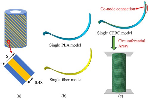
Table 1. Mechanical properties of PLA and Kevlar fibre.
3. Experimental results and discussion
3.1. Experimental results
3.1.1. Influence of fibre orientation on compression performance
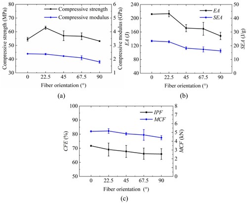
As shown in 3D printing path planning for the cylindrical layer, the fibre orientation refers to the sharp angle formed between the tangent line of the printing path on the cylinder and the generatrix line that passes through the point of tangency. As shown in (a), the compressive strength exhibited an initial rise followed by a subsequent drop as the fibre orientation changed from 0° to 90°. The compressive strength reached a maximum value of 62.92 MPa when the fibre orientation was 22.5°. The compressive modulus decreased as the fibre orientation increased. The CFRC energy absorption tubes demonstrated a maximum compression modulus of 2.39 GPa when the fibre orientation was 0°. As shown in (b), the EA and the SEA both increased as the fibre orientation decreased. The EA of the CFRC energy absorption tubes with the fibre orientations of 0° and 22.5° exhibited comparable values. However, the SEA of the energy absorption tubes at 0° was found to be higher. The MCF and the CFE decreased slightly as the fibre orientation increased, as shown in (c). The maximum CFE was 72%, when the fibre orientation was 0°. Hence, it was essential to choose the fibre orientation to achieve optimal energy absorption capability or load-bearing performance, in accordance with the specific requirement of the application.
Figure 5. Influence of fibre orientation on compressive performance: (a) Compressive strength and compressive modulus, (b) EA and SEA, (c) CFE and MCF.
presents a comparison between experimental and finite element simulation results of load-displacement curves for the 3D-printed CFRC energy absorption tubes with various fibre orientations. presents a comparison between experimental and finite element simulation results of the compression process for CFRC energy absorption tubes with various fibre orientations. Overall, the experimental and finite element simulation results showed better agreement, confirming the efficacy of the finite element modelling method employed in this paper. The compression process of the CFRC energy absorption tubes could be categorised into three stages: pre-crushing zone, post-crushing zone, and densification zone.
Figure 6. Load-displacement curves of experiment and simulation: (a) All specimens with different θ, (b) θ0°, (c) θ22.5°, (d) θ45°, (e) θ67.5°, (f) θ90°.
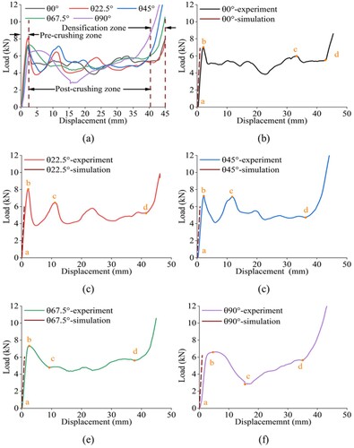
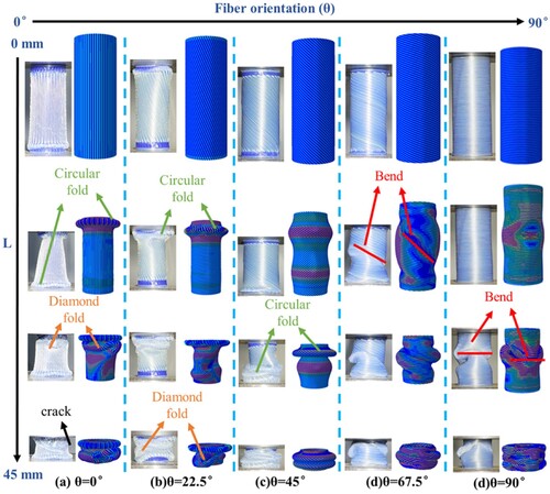
Figure 7. Experimental and simulated failure process with L(displacement) of CFRC energy absorption tubes with different fibre orientation: (a) θ0°, (b) θ22.5°, (c) θ45°, (d) θ67.5°, (e) θ90°.
During the pre-crushing zone, the CFRC energy absorption tubes exhibited linear elastic deformation, characterised by a rapid linear increase in the load value from point a. The stress cloud diagram reveals that, owing to the differing modulus of elasticity between the fibre and resin, the stress in the fibre was notably higher than that in the resin. This observation underscored the load-bearing function of the fibres in the crushing process. Upon reaching the initial peak load point b, the CFRC energy absorption tubes entered into the deformation phase, characterised by a decline in load and significant deformation of the cylinder. The fibres reached their load-bearing and yielding limits. Consequently, this resulted in a reduction in stiffness and a decrease in the load-carrying capacity of the rotary cylinder. Following this, the load fluctuated up and down with the displacement. Upon reaching point d, the densification stage commenced, characterised by the densification of the entire structure and a linear increase in load. displays the results of the displacement-load curves for the finite element simulation in the pre- crushing stage only. This limitation arose due to the presence of printing defects, which severely degraded the resin-fibre interface bonding compared to the finite element simulation. Consequently, a significant disparity existed between the displacement-load curves in the deformation stage.
However, as the print angle varied, the failure behaviour of the rotary cylinder during the deformation phase also changed. With the increase in fibre orientation from 0° to 45°, the CFRC energy absorption tubes underwent symmetric deformation from the end, resulting in a circular fold, followed by asymmetric deformation leading to the formation of a diamond fold. Subsequently, the load rapidly decreased after reaching the peak load point b. Additionally, the load decreased rapidly after reaching the peak load b point. At a fibre orientation of 45°, the CFRC energy absorption tubes consistently underwent predominantly symmetric deformation, characterised by the presence of only circular folds. Moreover, with increasing fibre orientation, the displacement-load curve of the CFRC energy absorption tubes exhibits greater fluctuation during the deformation stage. Specifically, as the fibre orientation increased from 45° to 90°, the CFRC energy absorption tubes bended from the middle along the fibre direction, dividing it into upper and lower parts. During this process, the displacement-load curve exhibits a gradual decrease with minimal fluctuation.
Analysis of strain maps from simulation results, as well as the deformation process and displacement-load curves of the energy absorption tube, suggests a significant influence of fibre orientation on the role of fibres in the compression process. This variation leads to distinct deformation processes in the cylinder, ultimately impacting its strength. Consequently, the failure process of continuous fibre energy absorption tubes can be controlled through the deliberate design of fibre orientation.
3.1.2. Influence of hatch spacing on compression performance
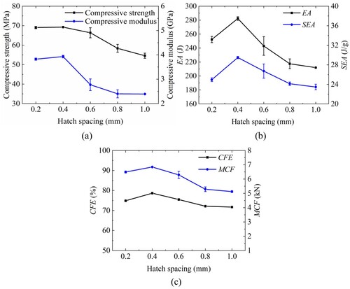
As shown in , hatch spacing, which represents the centre-to-centre distance between two adjacent fibres, is a crucial parameter in the 3D printing process. Hatch spacing has a significant impact on the forming accuracy, mechanical performance, and printing efficiency of 3D printing components. As shown in (a), the compressive strength and modulus exhibited a slight initial gain, followed by a subsequent drop when the hatch spacing was increased. With the hatch spacing of 0.4 mm, the maximum compressive strength and modulus were 69.25 MPa and 3.93 GPa, respectively. As shown in (b) and (c), the EA, the SEA, the MCF, and the CFE of the CFRC energy absorption tubes rose, followed by a subsequent drop as the hatch spacing changed from 0.2 to 1 mm. With the hatch spacing of 0.4 mm, the maximum EA and SEA were 282.36 and 29.49 J/g, respectively. The CFRC energy absorption tubes with the hatch spacing of 0.4 mm had the highest MCF and CFE, indicating superior stability and uniform force distribution during compression. In summary, depending on the specific application requirement, the selection of an appropriate hatch spacing is crucial to attaining ideal energy absorption characteristics or an ideal load-bearing performance.
Figure 8. Influence of hatch spacing on compression performance: (a) Compressive strength and compressive modulus, (b) EA and SEA, (c) CFE and MCF.
(a) displays the compression load-displacement curve of the CFRC energy absorption tubes with different hatch spacings, which could also be categorised into three stages: a pre-crushing zone, a post-crushing zone, and a densification zone. displays the compressive process of the energy absorption tubes with different hatch spacings. The CFRC energy absorption tubes entered the pre-crushing zone initially, where the load rapidly increased and reached the initial peak load. The load was concentrated at the end of the energy absorption tubes, producing the first fold. Subsequently, the load fluctuated up and down as the compressive displacement increased, and more folds developed during the post-crushing zone. Concurrently, the occurrence of fractures within or between layers started and proceeded to propagate along the energy absorption tubes, eventually resulting in the development of prominent longitudinal cracks. Finally, when the compressive displacement reached approximately 40 mm, the energy absorption tubes gradually entered the densification zone, and the load increased linearly.
Figure 9. Load-displacement curves of CFRC energy absorption tubes: (a) All specimens with different d, (b) d1, (c) d0.8, (d) d0.6, (e) d0.4, (f) d0.2.
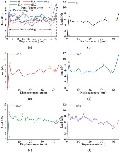
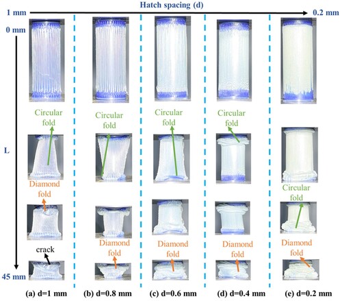
Figure 10. Failure process with L (displacement) of CFRC energy absorption tubes with different hatch spacings: (a) d1, (b) d0.8, (c) d0.6, (d) d0.4, (e) d0.2.
However, displacement-load curves with different hatch spacing had differences. (b–f) illustrates the load-displacement curves for hatch spacings of 1, 0.8, 0.6, 0.4, and 0.2 mm. In the figure, point a denotes the starting point, point b represents the initial peak load, point c indicates the second peak load and point d represents failure. The occurrence of the second peak load in the CFRC energy absorption tubes with hatch spacings of 1, 0.8, and 0.6 mm was noticed at a compressive displacement of 30 mm. There were fewer and smoother waveforms during the post-crushing zone. However, the second peak load of the CFRC energy absorption tubes with hatch spacings of 0.2 and 0.4 mm occurred at a compressive displacement of approximately 15 mm. The load-displacement curves for these both had more waveforms. In summary, the failure mode of 3D-printed CFRC energy absorption tubes can be effectively controlled by optimising the hatch spacing.
3.2. Discussion
3.2.1. Influence of fibre content
As shown in (a), during the process of 3D-printed CFRC energy absorption tubes, the aramid fibre content can be defined as the volume ratio of aramid fibre to the energy absorption tube. The volume of aramid fibre can be calculated by multiplying the cross-sectional area of the fibre bundle by the length of the printing path. The volume of energy absorption tubes can be determined by multiplying the cross-sectional area of the composite extruded from the nozzle with the length of the printing path. Therefore, the aramid fibre content in a 3D-printed continuous fibre energy absorption cylinder can be calculated using the following formula:
(15)
(15) where Sf is the cross-sectional area of the fibre bundle, h is layer thickness, and d is the hatch spacing.
Figure 11. (a) Diagram for calculating fibre content, (b) Fibre content of the 3D-printed CFRC energy absorption tubes with hatch spacings from of 0.2 to 1.0 mm.
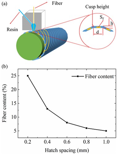
The correlation between the hatch spacing and aramid fibre content is illustrated in (b). As the hatch spacing increased from 0.4 to 1 mm, the fibre content gradually decreased. A reduction in the number of fibres inside the CFRC energy absorption tubes results in a diminished capacity to bear an axial load, hence causing a decline in the compressive performance (). When the hatch spacing was 0.4 mm and the fibre content was 12.5%, optimal compressive performance could be achieved. However, reducing the hatch spacing to 0.2 mm might cause inadequate impregnation of the internal fibres, consequently weakening the bonding capacity of the interface [Citation43]. Therefore, when the hatch spacing of the CFRC energy absorption tubes was reduced from 0.4 to 0.2 mm, there was a decline in compressive performance, despite an increase in the fibre content. The fibre content of CFRC energy absorption tubes can be precisely regulated by adjusting the hatch spacing during the 3D printing process, thereby achieving the specific energy absorption or load-bearing performance as needed.
3.2.2. Influence of failure mode
The compression failure process of continuous fibre-reinforced energy absorption tubes under quasi-static conditions is depicted in and . Variations in printing parameters resulted in different energy absorption tubes exhibiting three distinct failure deformation modes: progressive symmetric folding deformation, progressive mixed folding deformation, and bending deformation.
illustrates that the fibre orientation can influence the failure deformation pattern of 3D printed continuous fibre energy absorption tubes. For fibre orientations of 0° and 22.5°, the energy absorption tube exhibited progressive folding mixed deformation. Progressive mixed folding deformation was characterised by the formation of circular folds starting at the ends and continuing to form prismatic folds, which were stacked together as compression proceeds. When the fibre orientation was less than 45°, the axial stiffness of the fibre exceeded the circumferential stiffness. Therefore, at the onset of compression, the circumferential stiffness played a role in resisting deformation, leading to a more uniform stress distribution along the circumference and resulting in the formation of ring wrinkles. As compression progresses towards the centre, the influence of the circumferential stiffness of the fibres diminished, leading to an inconsistent distribution of stresses along the circumference. This resulted in the formation of diamond folds, leading to progressive mixed folding deformation.
As the fibre orientation increases to 45°, the deformation mode shifted to progressive symmetric folding deformation. Progressive symmetric folding deformation was characterised by the formation of annular folds exclusively during compression. At a fibre orientation of 45°, both axial and circumferential stiffnesses operated concurrently, resulting in uniform stress distribution along the circumferential direction throughout the compression process, leading to progressive folding deformation.
For fibre orientations of 67.5° and 90°, the energy absorption tube underwent bending deformation. Bending deformation was characterised by the absorption tubes bending directly along the direction of the fibres, dividing into upper and lower parts that subsequently fold together. For fibre orientations exceeding 45°, the fibre's capacity to withstand axial load decreased sharply, and its axial stiffness partially suppressed axial deformation. Consequently, the tube bended from the middle along the fibre direction, resulting in bending deformation.
According to it can be found that different fibre contents exhibit progressive mixed folding deformation during compression. These energy absorption tube deformations were characterised by the initial appearance of outwardly extending circular folds, followed by diamond folds. The number of folds produced varies with increasing fibre content. A higher number of folds resulted in more waveforms in the displacement-load curve. Throughout the compression process, fewer diamond folds were produced due to their longer formation time, resulting in fewer curve waves in the displacement-load curves of energy absorption tubes with smaller fibre content [Citation44]. Energy absorption tubes with a large fibre content asymptotically produced many circular folds rapidly at the beginning of compression, and began to produce diamond folds when the strain reached about 60%, while the cracks were getting longer and longer. Furthermore, due to the shorter wavelength of the circular folds, energy absorption tubes with larger fibre content produced more folds during compression. This phenomenon led to more curve waves in the displacement-load curve and an earlier appearance of the second peak load point. At the same time, the circular folds can guide the energy absorption tube to show more stable deformation process under compressive load, and thus had better energy-absorbing performance with higher fibre content. Additionally, circular folds can facilitate a more stable deformation process of the energy absorption tube under compressive load, resulting in improved energy-absorbing performance with higher fibre content [Citation45,Citation46].
In summary, the printing parameters can influence the compression performance of the energy absorption tubes by impacting the compression failure process of the cylinder. Therefore, controlling the printing parameters allows for achieving controllable compression performance of the continuous fibre energy absorption tube.
3.2.3. Interface of CFRC energy absorption tubes
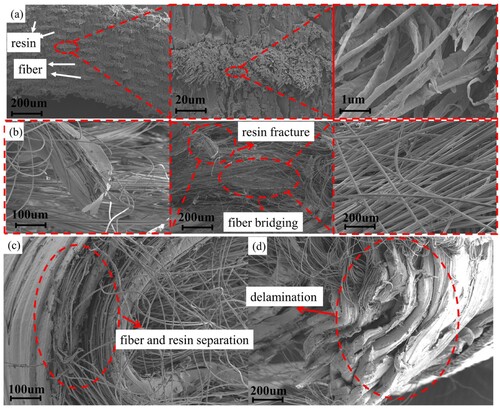
illustrates the cracks in CFRC energy absorption tubes during compression. To discover the primary causes of these cracks, an analysis of the resin-fibre interface microstructure was conducted before and after compression. The microstructural interface of the CFRC energy absorption tubes before compression was shown in (a). The aramid fibre bundle underwent complete matrix impregnation, resulting in effective bonding between the fibre and the matrix. The microstructure of the cracks in the CFRC energy absorption tubes after compression is illustrated in (b–d). The resin and the fibre were separated, and the fibre bridge phenomenon occurred at the crack, the phenomenon of resin fracture and stratification was also present. In addition, resin adhered to the fibre upon separation, as shown in (c), whereas (b) shows almost no resin on the bridged fibre. This revealed that fibre and resin separation was the main cause of the cracks in the CFRC energy absorption tubes during compression. Future research should concentrate on improving the interfacial adhesion between fibres and resin.
Figure 12. Microstructures and fracture patterns of CFRC energy absorption tubes: (a) Before compression, (b) Resin fracture and fibre bridging after compression, (c) Fibre and resin separation after compression, (d) Delamination after compression.
3.2.4. Comparison between cylindrical layered and flat layered strategies
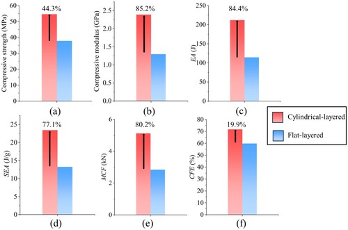
To compare the impact of different printing strategies on the compressive performance of CFRC energy absorption tubes, the flat layered planning strategy was also employed to fabricate tubes. Tubes were prepared at hatching spacing of 1 mm and layer thickness of 0.2 mm. The same static compression experiments were conducted. A comparison of the experimental results is presented in . Compared with the flat layered strategy, cylindrical layered printing strategy enhanced the compressive strength, compressive modulus, EA, SEA, MCF, and CFE of the CFRC energy absorption tubes by 44.3%, 84.4%, 80%, 77.1%, 80.2%, and 19.9% respectively. The cylindrical layered printing strategy facilitated fibre distribution along the axis, enhancing compressive performance. Additionally, the interlayer performance of the cylindrical layered printing strategy was better. Thus, it was determined that fibre distribution along the cylinder surface can significantly enhance the compressive performance of CFRC energy absorption tubes.
Figure 13. Comparison between cylindrical layered and flat layered: (a) Compressive strength, (b) Compressive modulus, (c) EA, (d) SEA, (e) MCF, (f) CFE.
3.2.5. Analysis of printing accuracy
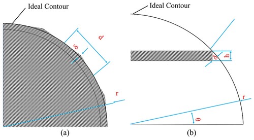
The cusp height might have occurred during the printing process of the CFRC energy absorption tubes because the cylindrical layered printing strategy for CFRC energy absorption tubes was used and the nozzle was flat (). This could have affected the surface quality of the CFRC energy absorption tubes. According to (a), the cusp high analysis model for the cylindrical layered strategy was established. The formula is presented as follows:
(16)
(16) where δ is the cusp height, r is the radius of the ideal contour, h represents the layer thickness, d is the hatch spacing, and α is the angle between the surface normal of the ideal contour and printing plane.
Figure 14. Cusp height analysis model: (a) Cylindrical layered, (b) Flat layered.
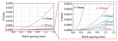
The ideal contour radii of 10, 100, 200, 300, 400 and 500 mm with a hatch spacing range of 0–1.5 mm were chosen to explore the effects of different parameters on the cusp height. The ideal contour radius contained a negative correlation with the cusp height and the hatch spacing contained a positive correlation with the cusp height, as shown in . Therefore, small hatch spacing could be chosen to achieve a good surface quality for energy absorption tubes with small radius.
Figure 15. Relationship between cusp height δ and hatch spacing d with different ideal contour radius r in cylindrical layered strategy.
Fibre can also be distributed on the cylinder surface to theoretically enhance the compression performance of CFRC energy absorption tubes with the flat layered printing strategy. However, this printing strategy has a noticeable step effect and low moulding accuracy. To compare the moulding accuracy between the cylindrical layered and flat layered strategies, the cusp high analysis model for the flat layered printing strategy was established based on (b):
(17)
(17) where h represents the layer thickness.
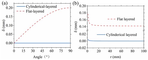
The cusp height of the flat layered is associated with layer thickness and has nothing to do with hatch spacing. However, the cusp height of the cylindrical layered strategy is associated with hatch spacing and has nothing to do with the layer thickness. To compare the effect of α on the cusp height between the flat layered and cylindrical layered strategies, the parameters of hatch spacing (0.2 mm), layer thickness (0.2 mm), and ideal contour radius (100 mm) were kept the same, while α was varied from 0° to 90°. As shown in (a), the cusp height of the CFRC energy absorption tubes for the flat layered strategy was positively correlated with the angle α, with a maximum of 1 × 10⁻¹ mm at 90°. In contrast, the cusp height for the cylindrical layered strategy had nothing to do with the angle α. The maximum cusp height was only 1 × 10⁻⁴ mm which was 1000 times smaller than that for the flat layered strategy. To compare the influence of the ideal contour radius r on the cusp height between flat layered and cylindrical layered strategies, ideal contour radius r was selected in the range of 0–100 mm for the same parameters (hatch spacing and layer thickness both at 0.2 mm, and angle α at 45°). As shown in (b), the cusp height for the cylindrical layered strategy was significantly smaller than that for the flat layered strategy.
Figure 16. Comparison between cusp height δ of cylindrical layered and flat layered with: (a) Layer thickness h of 0.2 mm, hatch spacing d of 0.2 mm, ideal contour radius r of 100 mm, (b) Layer thickness h of 0.2 mm, hatch spacing d of 0.2 mm, angle of 45°.
3.2.6. Demonstration of CFRC lightweight energy absorption tube based on cylindrical layered 3D printing
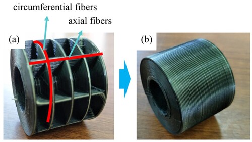
As shown in , the CFRC lightweight energy absorption tube was produced with the cylindrical layered 3D printing strategy. The manufacturing process involved the following printing parameters: Printing temperature of 220°C, printing speed of 100 mm/min, layer thickness of 0.2 mm, and hatch spacing of 1 mm. The lightweight energy absorption tube was primarily composed of an inner core and an outer skin. The inner core was primarily composed of intersecting circumferential fibres (with a fibre orientation of 90°) and axial fibres (with a fibre orientation of 0°) as shown in (a). Once all the inner cores were completed, the outer skin ((b)) of the lightweight energy absorption tube was printed with circumferential fibres, ultimately achieving the integrated manufacturing of the CFRC lightweight energy absorption tube. The use of the cylindrical layered printing strategy allowed for precise control over the continuous fibre arrangement on the cylinder surface, providing an innovative approach to the design and manufacture of high-performance, lightweight energy absorption tubes with potential applications in the aerospace industry.
Figure 17. CFRC lightweight energy absorption tube: (a) the inner core (b) the outer skin.
4. Conclusions
This study focused on the rapid manufacturing of 3D printed CFRC energy absorption tubes and discussed the impact of fibre orientations and printing parameters on the compressive properties and failure modes of CFRC energy absorption tubes.
The cylindrical layered 3D printing strategy was proposed to achieve precise control over the fibre distribution of CFRC energy absorption tubes. Compared to the flat layered approach, the cylindrical layered 3D printing strategy improved the compressive strength and total energy absorption of CFRC energy absorption tubes by 44.3% and 85.2%, respectively. Additionally, the cylindrical layered 3D printing strategy could significantly improve printing accuracy.
By adjusting the fibre orientation, the failure mode of the 3D printed CFRC energy absorption tubes could be controlled to regulate their energy absorption capability or load-bearing performance. When the fibre orientation increased, the failure mode of the energy absorption tubes transitioned from progressive mixed folding deformation to progressive symmetric folding deformation, ultimately to bending deformation. The compressive strength initially increased with fibre orientation from 0° to 90°, followed by a subsequent decrease. Additionally, both the energy absorption capability and compressive stability showed a decrease.
When the hatch spacing increased, the compression strength, energy absorption performance and compressive stability gradually decreased. Under quasi-static compression, the failure modes of the CFRC energy absorption tubes with different hatch spacings were consistent and characterised by progressive mixed folding deformation.
By adjusting the printing parameters, the fibre content and the printing precision of the CFRC energy absorption tubes could be controlled. Therefore, selecting a small hatch spacing and appropriate fibre orientation will result in CFRC energy absorption tubes with superior performance and high forming accuracy.
Based on these research findings, this novel manufacturing strategy shows significant potential for applications in 3D printing high-performance and high-precision CFRC energy absorption tubes.
Disclosure statement
No potential conflict of interest was reported by the author(s).
Data availability statement
The data that support the findings of this study are available from the corresponding author (Hou) upon reasonable request.
Additional information
Funding
References
- Kim J, Jeong M, Böhm H, et al. Experimental investigation into static and dynamic axial crush of composite tubes of glass-fiber mat/PA6 laminates. Compos Part B Eng. 2020;181:107590. doi:10.1016/j.compositesb.2019.107590
- Zia AA, Tian X, Liu T, et al. Mechanical and energy absorption behaviors of 3D printed continuous carbon/Kevlar hybrid thread reinforced PLA composites. Compos Struct. 2023;303:116386. doi:10.1016/j.compstruct.2022.116386
- Wong J, Altassan A, Rosen DW. Additive manufacturing of fiber-reinforced polymer composites: a technical review and status of design methodologies. Compos Part B Eng. 2023;255:110603. doi:10.1016/j.compositesb.2023.110603
- Ryzińska G, David M, Prusty G, et al. Effect of fibre architecture on the specific energy absorption in carbon epoxy composite tubes under progressive crushing. Compos Struct. 2019;227:111292. doi:10.1016/j.compstruct.2019.111292
- Ye H, Ma J, Zhou X, et al. Energy absorption behaviors of pre-folded composite tubes with the full-diamond origami patterns. Compos Struct. 2019;221:110904. doi:10.1016/j.compstruct.2019.110904
- Xie J, Waas AM. Predictions of delamination growth for quasi-static loading of composite laminates. J Appl Mech Trans ASME. 2015;82(8):081004. doi:10.1115/1.4030684
- Isaac CW, Ezekwem C. A review of the crashworthiness performance of energy absorbing composite structure within the context of materials, manufacturing and maintenance for sustainability. Compos Struct. 2021;257:113081. doi:10.1016/j.compstruct.2020.113081
- Abdullah NAZ, Sani MSM, Salwani MS, et al. A review on crashworthiness studies of crash box structure. Thin Walled Struct. 2020;153:106795. doi:10.1016/j.tws.2020.106795
- Qing X, Liao Y, Wang Y, et al. Machine learning based quantitative damage monitoring of composite structure. Int J Smart Nano Mater. 2022;13(2):167–202. doi:10.1080/19475411.2022.2054878
- Supian ABM, Sapuan SM, Zuhri MYM, et al. Effect of winding orientation on energy absorption and failure modes of filament wound kenaf/glass fibre reinforced epoxy hybrid composite tubes under intermediate-velocity impact (IVI) load. J Mater Res Technol. 2021;10:1–14. doi:10.1016/j.jmrt.2020.11.103
- Hu D, Zhang C, Ma X, et al. Effect of fiber orientation on energy absorption characteristics of glass cloth/epoxy composite tubes under axial quasi-static and impact crushing condition. Compos Part A Appl Sci Manuf. 2016;90:489–501. doi:10.1016/j.compositesa.2016.08.017
- Wang Y, Feng J, Wu J, et al. Effects of fiber orientation and wall thickness on energy absorption characteristics of carbon-reinforced composite tubes under different loading conditions. Compos Struct. 2016;153:356–368. doi:10.1016/j.compstruct.2016.06.033
- Alia RA, Al-Ali O, Kumar S, et al. The energy-absorbing characteristics of carbon fiber-reinforced epoxy honeycomb structures. J Compos Mater. 2018;53(9):1145–1157. doi:10.1177/0021998318796161
- Bakar MS A, Salit MS, Mohamad Yusoff MZ, et al. The crashworthiness performance of stacking sequence on filament wound hybrid composite energy absorption tube subjected to quasi-static compression load. J Mater Res Technol. 2020;9(1):654–666. doi:10.1016/j.jmrt.2019.11.006
- Xu J, Ma Y, Zhang Q, et al. Crashworthiness of carbon fiber hybrid composite tubes molded by filament winding. Compos Struct. 2016;139:130–140. doi:10.1016/j.compstruct.2015.11.053
- Wang B, Wu L, Ma L, et al. Mechanical behavior of the sandwich structures with carbon fiber-reinforced pyramidal lattice truss core. Mater Des (1980–2015). 2010;31(5):2659–2663. doi:10.1016/j.matdes.2009.11.061
- Almeida JHS, St-Pierre L, Wang Z, et al. Design, modeling, optimization, manufacturing and testing of variable-angle filament-wound cylinders. Compos Part B Eng. 2021;225:109224. doi:10.1016/j.compositesb.2021.109224
- Zhou J, Guan Z, Cantwell WJ. The energy-absorbing behaviour of composite tube-reinforced foams. Compos Part B Eng. 2018;139:227–237. doi:10.1016/j.compositesb.2017.11.066
- Zhu G, Wang Z, Huo X, et al. Experimental and numerical investigation into axial compressive behaviour of thin-walled structures filled with foams and composite skeleton. Int J Mech Sci. 2017;122:104–119. doi:10.1016/j.ijmecsci.2016.12.019
- Peng C, Tran P, Mouritz AP. Compression and buckling analysis of 3D printed carbon fibre-reinforced polymer cellular composite structures. Compos Struct. 2022;300:116167. doi:10.1016/j.compstruct.2022.116167
- Quan C, Han B, Hou Z, et al. 3D printed continuous fiber reinforced composite auxetic honeycomb structures. Compos Part B Eng. 2020;187:107858. doi:10.1016/j.compositesb.2020.107858
- Wang B, Ming Y, Zhou J, et al. Fabrication of triangular corrugated structure using 3D printed continuous carbon fiber-reinforced thermosetting epoxy composites. Polym Test. 2022;106:107469. doi:10.1016/j.polymertesting.2021.107469
- Tian X, Todoroki A, Liu T, et al. 3D printing of continuous fiber reinforced polymer composites: development, application, and prospective. Chin J Mech Eng Addit Manuf Front. 2022;1(1):100016. doi:10.1016/j.cjmeam.2022.100016
- Yin G, He Q, Zhou X, et al. Printing ionic polymer metal composite actuators by fused deposition modeling technology. Int J Smart Nano Mater. 2021;12(2):218–231. doi:10.1080/19475411.2021.1914766
- Alhijaily A, Kilic ZM, Bartolo ANP. Teams of robots in additive manufacturing: a review. Virtual Phys Prototyp. 2023;18(1):e2162929. doi:10.1080/17452759.2022.2162929
- Uşun A, Gümrük R. The mechanical performance of the 3D printed composites produced with continuous carbon fiber reinforced filaments obtained via melt impregnation. Addit Manuf. 2021;46:102112. doi:10.1016/j.addma.2021.102112
- Zeng C, Liu L, Bian W, et al. Compression behavior and energy absorption of 3D printed continuous fiber reinforced composite honeycomb structures with shape memory effects. Addit Manuf. 2021;38:101842. doi:10.1016/j.addma.2021.101842
- Zhang P, Sun S, Duan J, et al. Line width prediction and mechanical properties of 3D printed continuous fiber reinforced polypropylene composites. Addit Manuf. 2023;61:103372. doi:10.1016/j.addma.2022.103372
- Liu T, Yuan S, Wang Y, et al. Stress-driven infill mapping for 3D-printed continuous fiber composite with tunable infill density and morphology. Addit Manuf. 2023;62:103374. doi:10.1016/j.addma.2022.103374
- Saeed K, McIlhagger A, Harkin-Jones E, et al. Characterization of continuous carbon fibre reinforced 3D printed polymer composites with varying fibre volume fractions. Compos Struct. 2022;282:115033. doi:10.1016/j.compstruct.2021.115033
- Huang Y, Tian X, Wu L, et al. Progressive concurrent topological optimization with variable fiber orientation and content for 3D printed continuous fiber reinforced polymer composites. Compos Part B Eng. 2023;255:110602. doi:10.1016/j.compositesb.2023.110602
- Zhang G, Wang Y, Chen Z, et al. Robot-assisted conformal additive manufacturing for continuous fibre-reinforced grid-stiffened shell structures. Virtual Phys Prototyp. 2023;18(1):e2203695. doi:10.1080/17452759.2023.2203695
- Tian X, Liu T, Yang C, et al. Interface and performance of 3D printed continuous carbon fiber reinforced PLA composites. Compos Part A Appl Sci Manuf. 2016;88:198–205. doi:10.1016/j.compositesa.2016.05.032
- Bettini P, Alitta G, Sala G, et al. Fused deposition technique for continuous fiber reinforced thermoplastic. J Mater Eng Perform. 2017;26(2):843–848. doi:10.1007/s11665-016-2459-8
- Shi K, Yan Y, Mei H, et al. 3D printing Kevlar fiber layer distributions and fiber orientations into nylon composites to achieve designable mechanical strength. Addit Manuf. 2021;39:101882. doi:10.1016/j.addma.2021.101882
- Kong X, Luo J, Luo Q, et al. Experimental study on interface failure behavior of 3D printed continuous fiber reinforced composites. Addit Manuf. 2022;59:103077. doi:10.1016/j.addma.2022.103077
- Morales U, Esnaola A, Iragi M, et al. The effect of cross-section geometry on crushing behaviour of 3D printed continuous carbon fibre reinforced polyamide profiles. Compos Struct. 2021;274:114337. doi:10.1016/j.compstruct.2021.114337
- Isaac CW, Sokołowski A, Duddeck F, et al. Mechanical characterisation and crashworthiness performance of additively manufactured polymer-based honeycomb structures under in-plane quasi-static loading. Virtual Phys Prototyp. 2023;18(1):e2273296. doi:10.1080/17452759.2023.2273296
- Wang Y, Zhang G, Ren H, et al. Fabrication strategy for joints in 3D printed continuous fiber reinforced composite lattice structures. Compos Commun. 2022;30:101080. doi:10.1016/j.coco.2022.101080
- Goh GD, Neo SJC, Dikshit V, et al. Quasi-static indentation and sound-absorbing properties of 3D printed sandwich core panels. J Sandw Struct Mater. 2021;24(2):1206–1225. doi:10.1177/10996362211037015
- Song S, Xiong C, Yin J, et al. Mechanical property of all-composite diamond honeycomb sandwich structure based on interlocking technology: experimental tests and numerical analysis. Mech Adv Mater Struct. 2024;31(5):973–989. doi:10.1080/15376494.2022.2128123
- Ahmed AA, Susmel L. Additively manufactured PLA under static loading: strength/cracking behaviour vs. deposition angle. Procedia Struct Integr. 2017;3:498–507. doi:10.1016/j.prostr.2017.04.060
- Liu T, Tian X, Zhang M, et al. Interfacial performance and fracture patterns of 3D printed continuous carbon fiber with sizing reinforced PA6 composites. Compos Part A Appl Sci Manuf. 2018;114:368–376. doi:10.1016/j.compositesa.2018.09.001
- Hanssen AG, Langseth M, Hopperstad OS. Static and dynamic crushing of circular aluminium extrusions with aluminium foam filler. Int J Impact Eng. 2000;24(5):475–507. doi:10.1016/S0734-743X(99)00170-0
- Mamalis AG, Manolakos DE, Baldoukas AK, et al. Energy dissipation and associated failure modes when axially loading polygonal thin-walled cylinders. Thin Walled Struct. 1991;12(1):17–34. doi:10.1016/0263-8231(91)90024-D
- Toksoy AK, Güden M. The strengthening effect of polystyrene foam filling in aluminum thin-walled cylindrical tubes. Thin Walled Struct. 2005;43(2):333–350. doi:10.1016/j.tws.2004.07.007