
 ?Mathematical formulae have been encoded as MathML and are displayed in this HTML version using MathJax in order to improve their display. Uncheck the box to turn MathJax off. This feature requires Javascript. Click on a formula to zoom.
ABSTRACT
Robotic clay formwork three-dimensional printing combined with incremental concrete casting controls concrete's hydrostatic pressure and enables the production of building-scale structures. Clay formwork is self-demolding and less carbon intensive than concrete and polymer, often used in formwork additive manufacturing. This research investigates the recycling and reuse of clay to re-print formworks and tailors a self-compacting concrete formula with 60% reduced cement content and 90% larger maximum aggregate size. The study then explores integrating steel fibers and longitudinal rebars into the fabrication process to provide shear and bending reinforcement. When comparing the load-bearing behaviour of the fabricated beams against those cast traditionally using wooden formworks, the fabricated beams demonstrated 20% lower load-bearing capacity, with peak load mid-span deflections staying in a similar range. While more investigation is required to address formwork deformations using mixed steel fibers and recycled clay, this research paves the way for more sustainable concrete construction practices.
1. Introduction
The construction industry is under increasing pressure to reduce its disproportionate impact on global greenhouse gas emissions. In 2020, buildings constituted 36% of the world's total energy demand and contributed to 37% of energy-related CO2 emissions [Citation1]. The worldwide consumption of building materials experienced a threefold increase, surging from 6.7 billion tons in 2000 to 17.5 billion tons in 2017. Among these materials, concrete, aggregates, and bricks emerge as the most commonly employed building elements [Citation2]. Also, the manufacturing of cement, a pivotal ingredient in concrete, is energy-intensive and contributes to 5–8% of total global CO2 emissions [Citation3,Citation4]. In addition, formworks contribute to waste production and, therefore, to the total cost and carbon emissions of concrete construction, particularly for bespoke building components [Citation5,Citation6]. Most formworks are discarded after construction, and formwork waste can represent a substantial portion, ranging from 20% to 30%, of the total construction waste [Citation7]. The [Citation8] reported a substantial need for increased investment in research, development, and advanced equipment to recover and process construction, renovation, and demolition waste, with a specific emphasis on cement-based materials. Efforts to decarbonise the cement sector are strengthened by adopting sustainable alternatives for concrete mixtures and formwork material, replacing traditional methods [Citation9].
Digital fabrication with concrete, including formwork three-dimensional (3D) printing through material extrusion, is an alternative approach to customisation in concrete construction with optimised and bespoke shapes to increase productivity, reduce construction waste and labour, and decrease the cost of producing complex forms [Citation10,Citation11]. Common materials used in formwork extrusion are concrete and polymers. 3D-printed concrete formworks usually do not have a load-bearing capacity and act as lost formwork. They are frequently used for time efficiency, minimised waste, and geometrical freedom for prefabrication [Citation12,Citation13] or in-situ construction [Citation14–17] along with steel reinforcing cages for structural partitions (i.e. columns or shear walls). Despite the aforementioned potentials, digital fabrication with concrete, including 3D printing, typically has a larger carbon footprint than conventional casting due to mixes with smaller maximum aggregate size and twice the cement content, coupled with lower durability due to higher drying shrinkage [Citation9].
Polymer formworks are typically printed as a removable mold using Fused Deposition Modeling (FDM) [Citation18–20] or extruded as stay-in-place insulation foam for building elements [Citation21,Citation22]. The recyclability of polymer formworks made from polyethylene terephthalate glycol (PETG) has been recently investigated in [Citation23], where a decrease in mechanical performance was reported after one cycle. The removal of polymer formwork is labour-intensive and requires local heating. Moreover, the removed pieces require cleaning off any concrete or other residues before recycling.
Achieving desirable structural performance is a recurring challenge in digitally fabricated concrete [Citation24], mainly due to the difficulty of integrating reinforcement into most of these technologies [Citation25,Citation26]. Investigations on the structural performance of concrete structures produced with extruded formwork include [Citation27,Citation28] for concrete as well as [Citation29,Citation30] for polymer formworks. Also, the durability of the produced elements and the integration of the techniques into mass-market applications and building codes are continuously examined [Citation31].
Clay extrusion originated from the Contour Crafting fabrication process for ceramics [Citation32]. Wet clay displays plasticity, allowing it to be extruded like the traditional clay coil pot method. Clay, along with other earth-based materials, has been investigated for the printing of small-scale and architectural applications [Citation33–36] as well as large-scale construction of facades and housing [Citation37,Citation38]. The resurgence of interest in earth construction, coupled with digital fabrication technologies, showcases its potential as a modern, environmentally friendly, and economically beneficial method. However, despite these advancements, earth construction still falls short in workability and structural performance, as well as in material delivery systems, to fully automate the construction process.
Clay 3D printing as a formwork innovation for concrete was first developed by Wang et al. [Citation39] investigating water-to-clay ratios and a method to withstand concrete's hydrostatic pressure by stacking and attaching 200 mm height segments of casts to reach a height of 1.4 m. Wang et al. [Citation40] also performed a parametric study on clay deformation due to concrete's pressure by printing 200 mm height cylindrical molds with varying diameters, extrusion layer heights, and wall thicknesses, showing that a reduction in cylinder diameter and layer height, as well as an increase in wall thickness, proved to reduce deformations in clay. Other recent studies concentrated primarily on smaller, decorative prototypes. In their experimentation with diverse molding techniques consisting of simple formwork, formwork with external/internal plastic or aluminum membranes, and formwork in a sandbox, Alonso Madrid et al. [Citation41] noted an enhanced ease of clay reuse when employing membranes. Despite this, the quality of the concrete pieces produced remains somewhat dubious, even with membrane use. Hunt and Arthur [Citation42] also presented a clay and paper formula as a mold for concrete and claimed its potential for recyclability.
While clay material boasts a smaller carbon footprint than concrete and polymerFootnote1, and offers the advantage of self-demolding formwork that could potentially eliminate waste, its limited resistance to the hydrostatic pressure of concrete presents difficulties in fabricating bespoke and building-scale prototypes. In our recent work, we introduced a method that integrates incremental clay printing and concrete casting to control the hydrostatic pressure of concrete [Citation43,Citation44]. The integration of stiffeners provided additional strength to the formwork, creating a unique column of 1.3 m in height featuring intricate curves and openings. The study also presented an effortless demolding process for the clay formwork and its potential for recycling and reuse.
1.1. Summary and problem statement
Cement production is energy-intensive and contributes to a considerable fraction of global CO2 emissions. Additionally, formworks contribute to a large portion of construction waste and the overall cost and carbon footprint of projects. Exploring digital fabrication methods like formwork 3D printing offers potential benefits such as increased productivity, reduced waste, and lower costs for producing bespoke forms, increasing efficiency and geometric freedom in construction processes. However, the structural performance and integration of digital fabrication techniques into building codes and mass-market applications remain active research areas. Also, other than durability issues, digital fabrication with concrete often results in a larger carbon footprint than traditional methods due to mixes with smaller aggregate sizes and higher cement content. Moreover, polymer formworks are being investigated for their recyclability despite challenges related to their removal and the necessity of cleaning before recycling.
The use of earth-based material in 3D printing for construction purposes is being actively researched, leveraging its natural properties for eco-friendly and economical construction. However, earth construction continues to face challenges in terms of structural performance, functionality, and automation, hindering the reduction of manual labour and the improvement of both efficiency and construction quality. Clay formwork extrusion has shown promise in small-scale and architectural applications, as our previous study showcased a customisation method to create a building-scale and bespoke concrete column. Many of the mentioned limitations regarding the construction with earth-based materials, such as lack of automation and investigation of the material performance, also apply to using clay as formwork for concrete. Our ongoing research aims to address these issues, paving the way for more sustainable construction practices using digital fabrication.
1.2. Objectives and contributions
Building upon our previous studies [Citation43,Citation45], this paper investigates creating cement-reduced and load-bearing reinforced concrete prototypes using clay formwork. The two primary objectives are to (1) assess the potential for reducing the carbon footprint of our method by investigating (i) the viability of using an accelerated self-compacting concrete (SCC) with larger aggregates and lower cement than typical mixes used in digital concrete processes, and (ii) the recycling and reuse of clay for re-printing of the formworks, as well as (2) explore the fabrication of load-bearing concrete elements by (i) incorporating steel fibers and reinforcing bars (rebars) to enhance shear and bending capacity, and (ii) comparing the overall structural performance of the fabricated beams with conventionally cast beams using wooden formworks.
This study represents a step forward in digital fabrication with concrete utilising a less carbon-intensive formwork material than concrete and polymer. The research showcases a method with the potential to reduce construction waste and facilitate the creation of bespoke architectural and structural elements. The comparative analysis of beams fabricated with this method against traditional wooden formworks provides initial empirical evidence, setting a benchmark for future advancements in the performance and integrity investigation of construction using earth-based materials.
2. Materials and methods
This section presents a methodology to address the mentioned objectives using an incremental clay printing and concrete casting technique. The fabrication setup includes a 6-axis industrial KUKA KR 120 robot arm [Citation46] mounted on a linear track and equipped with a clay extrusion end effector. Details of the fabrication setup, digital design-to-fabrication workflow, extrusion toolhead, and control method can be found in [Citation44]. The only addition to the setup is a 2D laser profile scanner (Gocator 2300 Series from [Citation47]) mounted on the robot arm to scan the fabricated beams and measure the formwork deformation.
In this section, we tailor a conventional SCC mix with reduced cement content and a larger maximum aggregate size, as well as examine the reuse of the removed clay formwork to re-fabricate new prototypes. This includes evaluating the compatibility of the tuned concrete formula and recycled clay to our incremental printing and casting method, as well as the total deformation of the formworks. We also explore the integration of short steel fibers and longitudinal rebars into the fabrication of concrete beams to provide shear and bending reinforcement. We then conduct a series of structural bending tests using non-recycled and recycled clay with two fiber integration methods to investigate the load-bearing capacity and provide a comparative analysis with a conventional casting technique.
Section 2.1 covers the specifications of clay, concrete, steel fibers, and rebars utilised in the experiments. We then discuss the fabrication process of the reinforced concrete beams (Section 2.2), the clay's recycling process (Section 2.3), the scanning process to measure formwork deformations (Section 2.4), and the structural tests (Section 2.5).
2.1. Materials
2.1.1. Clay
The formwork extrusion material is a terracotta clay (RO-82M from [Citation48]); most of the body content is redart, an iron-bearing clay, while the remainder includes ball clay for plasticity and 3% fine mullite grog for smoother body and stability ( (left)). shows the properties of this commercial ready-to-use clay tested at [Citation49] according to American Society for Testing Materials' [Citation50,Citation51] standard tests. The moisture content of the tested clay is about 27%, indicating that it is in a plastic range based on its Atterberg limits ().
Figure 1. Commercial ready-to-use terracotta clay block (left), slump flow test of the SCC mix with a spread range of 500–600 mm (center), and steel fibers (right).
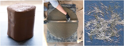
Table 1. Terracotta clay properties.
2.1.2. Concrete
In this study, we fine-tuned a conventional SCC mix from [Citation52] to reduce the carbon footprint of the concrete mix used in our previous research [Citation44]. The use of around 90% increased maximum aggregate size (9.5 mm vs. ) allowed 60% lower cement content (14% vs. 35%) (). Also, a spread of over 500 mm in the slump test ( (center)) confirmed the self-compacting nature of the used mix to provide the required workability and fill narrow areas of the formwork.
Table 2. Concrete composition (% of the total mix weight).
The casting process uses a set-on-demand technique [Citation20,Citation53] with retarder and accelerator admixtures (). However, our SCC mix contains half the cement content and more than twice the maximum aggregate size compared to conventional set-on-demand mixes. Several tests were performed to quantify the required accelerator dosage that enables proper workability of the mix and a sufficiently low formwork pressure. shows sample trial mixes cast into cylindrical clay formworks to test the consistency, adjust the retarder-acceleratorFootnote2 proportions, and examine the achievable print heights.
Figure 2. Sample trials to fine-tune the SCC mix, and adjust the retarder and accelerator proportions.
During the fabrication process, the retarder is added to the original concrete mix to delay the hydration and keep the concrete fresh for a longer duration (typically 2-3 h). The accelerator is manually mixed with a smaller batch of the retarded concrete 1-2 min before casting to speed up the setting of the concrete and reduce the hydrostatic pressure on the formwork and, therefore, prevent large deformations and failure in the plastic clay.
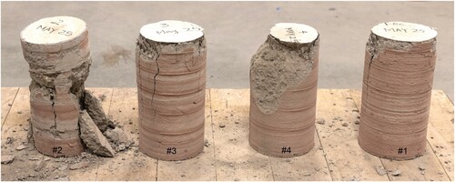
To estimate the concrete's compression strength, we cast four cylinders of 150 mm diameter and 300 mm height with a similar sequential printing and casting process explained in Section 2.2 and tested them 26 days after casting (). We observed low compressive strengths with an average of 17 MPa (2466 psi) for samples 1 and 3 and ignored the low strength values for samples 2 and 4, which showed local crushing. The potential reason behind this reduced value could be the effect of uneven surface contact with the testing machine as well as cold joints between the concrete layers, which should be investigated in future research.
Figure 3. Cylinder samples used in the compression test; samples 2 and 4 showed lower compressive strengths.
2.1.3. Reinforcement
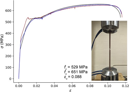
We used longitudinal steel rebars to provide bending reinforcement. The rebars have a diameter of 15.9 mm (5/8 inch) with a nominal strength of 414 MPa (60 ksi). The stress-strain curves of the three rebars tested in direct tension, including the average dynamic values for yield stress , ultimate stress
, and ultimate strain
are presented in . As shown, the yield stresses are above 500 MPa and higher than the nominal value.
Figure 4. Stress-strain curves under the direct tension for three #5 rebars (Ø = 15.95 mm, ) including the average dynamic values for yield stress
, ultimate stress
, and ultimate strain
.
To provide shear reinforcement, we utilised brass-coated high carbon steel fibers with surface striations, a length of 6 mm, a diameter of 0.2 mm, and a nominal tensile strength of 2847.5 MPa (413 ksi) from [Citation54] ( (right)). Two alternative processes were explored to distribute the fibers: (1) mixed into the concrete batch for each cast layer and (2) spread on top of each cast layer. The fiber content was 0.5% of the concrete weight for the mixed fibers and reduced to 0.2–0.3% for the interlayer fibers to account for their more favourable orientation.
2.2. Fabrication process
Section 2.1 provided an overview of the material properties, including the tuned reduced-cement SCC mix. Before exploring the recycling and reuse of formwork, we present the fabrication process of reinforced concrete beams with the integration of steel fibers and longitudinal rebars to address the objective of evaluating the load-bearing behaviour in the structural tests (Section 2.5).
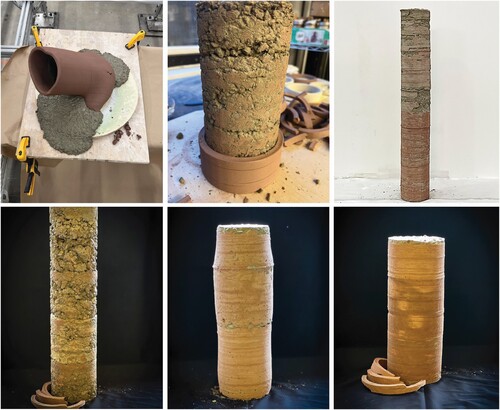
shows an overview of the fabrication process. The beams using 3D-printed clay formwork are fabricated vertically; each beam is 1 m long with a rectangular cross-section of () and cast using a total of 3.5 retarded batches of 17.9 kg SCC mix. The clay is printed with a bead height of 1.5 mm, a width of 6 mm, and a printing speed of
. The printing speed was determined empirically to ensure adequate layer adhesion, dimensional accuracy, and curing time for the concrete. Also, the bead height was systematically investigated in our earlier study [Citation44], where the heights below 2 mm resulted in minor formwork deformations and the least porosity. The average total fabrication time of each beam is approximately 6.5 h (excluding the insertion of longitudinal rebars and grouting).
Figure 5. Overview of the fabrication process: (top) printing and casting sequence, and (bottom) removal of the self-detached external formwork, installation of the longitudinal rebars (after the removal of the internal formwork), grouting the void, and the finished beam before screwing the anchorage bolts.
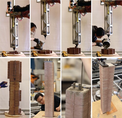
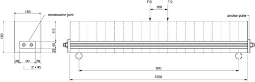
Figure 6. Beam properties and structural test configuration, the dashed lines show the casting layers (dimensions in mm).
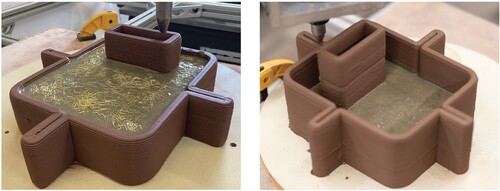
The fabrication of each beam begins with mixing a 17.9 kg batch of retarded concrete and printing the first 5 cm height of clay formwork. After each sequence of clay printing, a small concrete batch (around 2.5-2.6 kg to fill up the 5 cm layer) mixed with a 2% accelerator is cast into the formwork. We used a small trowel for slight manual vibrations after each cast to avoid air entrapment. The wait time between casts is 15–20 minutes to allow (1) the extrusion of the following 5 cm layer and clay extruder tube change if necessary and (2) the concrete to set and minimise the pressure on the printed formwork. The accelerator content was reduced to 1% towards the end of each large concrete batch.
The formwork includes four stiffeners on each side to provide extra resistance to withstand the hydrostatic pressure from fresh concrete and prevent excessive formwork deformation (). As mentioned, the steel fibers were either mixed into the small concrete batch right before casting or spread on top of each casting layer (). To accommodate the longitudinal rebars for bending reinforcement, a void is printed alongside each cross-section ( and ) and kept empty until the entire formwork (exterior and interior) is removed.
Figure 7. Formwork cross-section with four stiffeners and an internal void: interlayer (left) and mixed (right) fibers.
At the end of the printing and casting sequence, the top of the formwork is covered with a damp towel for a few hours to keep the clay moist and prevent it from absorbing extra water from the concrete. The exterior formwork dries, self-demolds, and can be easily picked up after 2-3 days (). The beam is then covered to avoid dehydration (only the void part is left exposed on either end to allow the interior clay to dry). The internal formwork required 6-7 days to dry and was removed using a long chisel. After removing the formwork entirely, two rebars were fixed on one side of the vertically placed beam, the void was grouted with the SCC mix including 2% accelerator, and then the bars were anchored to steel plates on both sides of the beam (). The reinforcing bars were welded with threaded ends before insertion, allowing for anchorage via hex nuts. The beams were covered in the laboratory until the testing day, 14 days after the initial casting.
2.3. Recycling and reuse of clay
In addition to fine-tuning the concrete mix to reduce the carbon footprint, we aim to investigate waste reduction by recycling the removed clay formwork from the fabrication process and evaluating its material properties and compatibility to re-produce new prototypes.
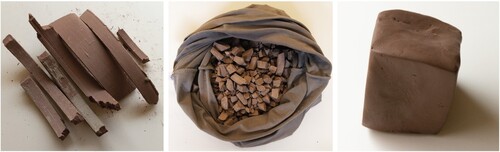
After clay dehydration and demolding within 2-3 days of casting the concrete, there is usually minimal concrete residue on the detached formwork, as seen in (left). This residue does not drastically affect the quality of the recycled clay and re-extrusion. The recycling process of the retrieved formwork follows these steps: (1) Allow the collected detached formwork pieces to dry completely within 5–7 days. (2) Place approximately 2.5 kg of dried clay in a pillowcase made from soft and porous microfiber material. For our clay extrusion setup, each tube required about 7.5 kg of dried clay. (3) Hammer the encased dried clay into smaller pieces ( (center)). (4) Twist the filled pillowcase, tie it, place it into a bucket full of water, and let it sit for an hour. (5) Hang the fabric containing wet clay securely, allowing it to dehydrate for about five days until it stops dripping and feels firm. (6) Unfasten the pillowcase, and before taking the clay out, forcefully flatten it by slapping it to a wooden or plaster surface to remove any excess water. At this point, the clay should be firm enough for wedging. (7) Remove the flattened clay from the fabric, cut it into a few pieces, stack the pieces, and wedge manually (spiral wedging) to homogenise it, release entrapped air bubbles, and improve its plasticity and workability. (8) After making sure the wedged clay has a good consistency, cover the resulting block ( (right)) with plastic until required. The formworks printed from recycled clay utilised the same extrusion settings as non-recycled clay. A sample of the recycled clay was also tested for material characterisation, presented in Section 3.1.
Figure 8. Recycling process: demolded formwork (left), crushed pieces in the fabric (center), kneaded clay ready for extrusion (right).
2.4. Formwork deformation
To evaluate the compatibility of the tuned SCC mix as well as the recycled clay with our incremental printing and casting method, we used a 2D laser profiler end effector to scan the beams after their complete fabrication to quantify the total clay deformation. The laser profiler captured a high-resolution point cloud with less than 2 mm spacing. The scanning process performed two vertical passes from the two opposite corners of each beam. The output point clouds characterise the deformations of the formwork when compared to the reference digital model. We refer to our recent article, Adel et al. [Citation55], on the details of the method and applied algorithms for calculating the point cloud deviations.
To summarise, we run a sampled point cloud from the reference digital model and the scanned point cloud through an iterative closest points (ICP) algorithm [Citation56] to minimise the total deviation between the two sets, aligning the scanned beam to the reference model. The algorithm then computes the closest distance between each scanned point and the reference model, which estimates the formwork deviations. Section 3.2 presents the deformation results.
2.5. Structural tests
We designed experiments to test the load-bearing behaviour of six specimens listed in ; four were fabricated with 3D-printed clay formwork, and two with conventional wooden formwork. From the four beams fabricated with clay formwork, two utilised ready-to-use non-recycled clay, and the remaining two utilised recycled clay. Within each categorical pair, one beam utilised mixed fibers, and the other utilised interlayer steel fibers. However, the fabrication of the beam with the recycled clay and mixed fibers (B4-RCL-M) failed due to excessive clay deformations in a few spots, and the time sensitivity of the project schedule did not allow for the re-fabrication of this beam. In the case of the conventional wooden formworks, we cast two identical beams horizontally using an identical SCC formula and mixed fiber content with a 2% accelerator. Due to the limited volume of the concrete mixer, the horizontal casting was performed in several layers with a time interval of 5–10 min.
Table 3. Overview of the beam specimens.
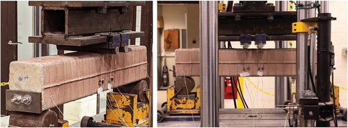
The beams were tested 14 days after the initial casting in a four-point bending test setup, with a span of 900 mm and load spacing of 100 mm, as depicted in and . We installed four pairs of markers on the beams to track the 3D kinematic motions of the critical locations using the Optotrak Certus system from [Citation57] (). The testing device applied the load in a deformation-controlled mode with a starting speed of up to the propagation of the initial cracks.
Figure 9. Four-point bending test setup with four pairs of kinematic tracking markers installed on the beam's surface.
Depending on how effectively the fibers would behave as shear reinforcement, we considered the strength of the beams to fall between their full bending capacity and their shear capacity, assuming no shear reinforcement was present. According to [Citation58] (ACI 318-14) and considering the average material properties ( and
), the bending capacity of the beams amounted to 21.4 kNm (ACI Section 22.2) and their unreinforced shear capacity to 16.6 kN (ACI Equation 22.5.51), with the maximum value of the applied load ranging between 33.2 and 95.0 kN.
3. Results and discussion
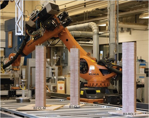
shows the three successful fabricated beams using 3D-printed clay formwork. This section presents the results of using recycled clay for re-fabrication, the formwork deformation analysis, and the structural performance of the beams compared to the traditionally cast prototypes.
Figure 10. The three beams fabricated with 3D-printed clay formwork; the beam with recycled and reused clay is on the right side, with the exterior formwork just removed.
3.1. Recycled formwork
compares the properties of the commercial ready-to-use clay with the recycled clay formwork, both tested at [Citation49]. As mentioned in Section 2.5, the second beam with recycled clay (B4-RCL-M) had excessive deformations due to fresh concrete pressure, cracked at two locations, and eventually failed. We speculate that the reduced compression and shear strength and higher moisture content of the recycled sample presented in could have contributed to this failure. Future investigations should aim to more precisely isolate and understand the variables affecting the performance of clay as formwork, such as precise investigation of the required clay rheology to achieve a proper buildability and its interaction with the surrounding air and fresh concrete, as well as the environmental effects (e.g. temperature and humidity) on the concrete mix and additional weight of concrete due to mixed fibers.
Table 4. Terracotta clay properties (non-recycled vs. recycled).
In the case of the beam successfully fabricated with recycled formwork (B3-RCL-I), the print quality and the resulting concrete beam had minor differences compared to the beams produced with non-recycled clay (). The slight differences might be due to over-extrusion caused by a nozzle clogged with concrete particles. This could be resolved by ensuring the formwork is dry enough to self-detach with minimal concrete residue and removing any large aggregates attached to the formwork before starting the recycling process. Increasing the nozzle size could be another solution. However, the extrusion rate, bead height, and wall thickness should be re-examined and adjusted accordingly. The formwork deformations and structural performance of the beam cast with recycled clay are discussed in Sections 3.2 and 3.3.
3.2. Formwork deformation
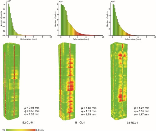
shows the deviations of the scanned point clouds (as-built) from the reference digital beam model (as-planned) using methods detailed in [Citation55]. The deviations are almost equivalent to the total formwork deformations, except for the ridges at the locations of stiffeners, where the continuous vertical lines show up in the heat maps of . The average deviation for beam 1 (B1-CL-I) is 0.91 mm, with a median of 0.53 mm and a standard deviation of 1.52 mm. The average deviation for Beam 2 (B2-CL-M) is 1.68 mm, with a median of 1.19 mm and a standard deviation of 1.79 mm. For beam 3 (B3-RCL-I) with recycled formwork, the average deviation is 1.27 mm, with a median of 0.85 mm and a standard deviation of 1.77 mm. The increased deformations in the case of beam 2 could be due to the concrete's increased weight with the mixed fibers. Also, when comparing both beams with interlayer fibers (beams 1 and 3), the increase in deformations of beam 3 with recycled clay could result from lower material strength and higher moisture content.
Figure 11. Formwork deformations as: (top) histograms with a bin size of 0.5 mm, and (bottom) heat maps with reported average (μ), median (η), and standard deviation (σ). The continuous vertical red/yellow lines in the heat maps are related to ridges caused by the formwork stiffeners and can be ignored.
3.3. Structural tests
shows the load-displacement curves resulting from the four-point flexural tests, with summarising the values for the ultimate load, , mid-span deflection,
, at
, and failure modes. Beam 1 (B1-CL-I) experienced a premature anchorage failure, likely caused by improperly applying the longitudinal reinforcement anchoring on one side of the beam. The results of this beam are not representative and are neither displayed in nor .
Figure 12. Load-displacement behaviour. shows the values at the ultimate load marked with circles and their corresponding deformation. The curve for B1-CL-I is not presented because of the premature anchorage failure.
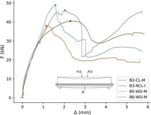
Table 5. Summary of the test results presented in , is the ultimate load and
is the mid-span deflection at
.
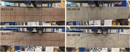
Regardless of the casting technique and formwork material, the overall behaviour was similar in all cases, with the ultimate load, , independent of the utilised strategy for the fiber shear reinforcement. The crack patterns were also similar; after an initial phase in which the beams remained uncracked, a few wide-spaced flexural cracks formed in the region close to the midspan. Later, diagonal shear cracks formed, where beams 3 (B3-RCL-I) and 6 (B6-WD-M) displayed diagonal cracks on both sides (). Despite the initial stable progression of the shear cracks, a brittle shear failure occurred in all beams. Beam 3 with the recycled clay formwork showed concrete spalling around the top of the rebar void on one side, indicating a weak construction bond. However, compared to beam 2 (B2-CL-M), it performed stronger with a minor second load peak after the diagonal crack opening, which could result from the interlayer fibers activation (). Also, although beams 5 (B5-WD-M) and 6 (B6-WD-M) were cast and reinforced similarly, a second load peak in beam 6 () after the stabilisation of the second shear crack could be interpreted as extra aggregate interlocking or more activation of the mixed fibers.
Figure 13. Diagonal tension shear failure of the four tested beams close to failure (80-90% of the peak load).
The mean value of the ultimate load amounts to 43.3 kN, which is within the calculated capacity range from Section 2.5 (33.2 kN < 43.3 kN < 95.0 kN) and close to the shear capacity without stirrups. This confirms the softening of the fibers (mixed or interlayer) and their insufficiency in contributing to the shear strength, causing a brittle behaviour and shear failure. The equivalent concrete tensile stress provided by the fibers can be estimated using a fiber engagement model that assumes a fiber pull-out with a constant bond strength over the fiber length [Citation59,Citation60], which subjects to future research.
The ultimate load, , in beams 5 and 6 cast with wooden formwork is around 20% higher than beams 2 and 3, with the mid-span deflections at the peak load,
, staying in the same range for both casting techniques (). The increase in the maximum load of the beams cast with wooden formworks could be attributed to horizontal versus vertical concrete casting that affected the bond between the cast layers. Also, clay water absorption from concrete and early shrinkage could cause this reduction. Moreover, the weak bond around the construction joint, caused by integrating the void for rebars, could decrease the shear transfer.
4. Conclusions
This article explored the load-bearing performance of concrete elements fabricated through 3D-printed clay formwork. The study investigated the fabrication of reinforced concrete beams utilising a tailored self-compacting mix and explored the use of recycled clay. The successfully developed less carbon-intensive SCC formula with 60% reduced cement content and 90% larger maximum aggregate size showed proper flowability and facilitated grouting. The study also presented a process for recycling and reusing clay and compared the material properties and formwork deformations to the non-recycled formwork; the print quality, formwork deformation, and the resulting concrete beam showed minor differences when using interlayer fibers. The use of mixed fibers caused more formwork deformations, and, in the case of recycled clay, the formwork failed during fabrication. We speculate that this behaviour could result from increased pressure of the fresh concrete with mixed fibers and reduced material properties of recycled clay; however, further investigation should focus on meticulously identifying and analysing other factors that impact the formwork deformations and performance of recycled clay. This involves an in-depth examination of the material's properties and buildability post-recycling and assessing how these influence the compatibility with fresh concrete in scenarios such as varying environmental conditions (e.g. humidity and temperature fluctuations), which could affect the drying and curing processes of fresh concrete and clay.
In addition, the study applied a methodology for reinforcing the concrete elements by integrating a continuous printed void to accommodate longitudinal rebars for bending strength. The structural tests showed similar brittle shear failure and crack progression across different casting techniques, which was not affected by the strategy used for fiber shear reinforcement. The fabricated beams with clay formwork showed 20% lower load-bearing capacity than the traditionally cast beams, with the mid-span deflections at the peak load staying in the same range for both casting techniques. This decrease could be attributed to differences in casting orientations affecting the interlayer bonding, clay water absorption from concrete, as well as the weak construction bond and shear transfer around the longitudinal void. The concrete interlayer bonding can be enhanced by increasing the interlocking between layers or applying active agents to the layer surface, as is often suggested in concrete 3D printing techniques [Citation61,Citation62]. Also, solutions for increasing the bond in the construction joint (i.e. surrounding the built-in void for the rebars), such as keeping the interior clay or making a rough void to increase interlocking [Citation29], should be investigated.
Finally, the mean ultimate load observed was 43.3 kN, within the expected range and indicative of the fibers' limited contribution to shear strength, leading to brittle failure modes. Future research has to further investigate the role of fibers in concrete tensile stress through a fiber engagement model. Overall, the study demonstrated promising characteristics of clay as a reusable formwork to create structural elements and to serve as a low-carbon and cheap alternative to extruded polymer and concrete formworks. The following section outlines limitations and potential directions for further exploration.
4.1. Limitations and outlook
The current fabrication process is inefficient due to the clay tube capacity limitation, which necessitates frequent tube changes and causes production slowdown. To address this, recent advancements in large-scale earth-printing, utilising a continuous pumping system [Citation63,Citation64], present a more productive avenue for fabricating building-scale elements. Also, other manual tasks such as adding accelerator and fibers, concrete casting, and rebar installation can be automated. Expanding the fabrication setup into a multi-robotic cooperative workcell equipped with industrial robotic arms or mobile robots [Citation65], as well as customised feeding systems and toolheads, facilitate a seamless and continuous production process. The multi-robot setup could include a robot arm responsible for cutting, bending, placing, and welding the rebars at each sequence [Citation66], reducing the time lag between casting and grouting, eliminating cold joints, and allowing the reinforcement of optimised and curved shapes. The formwork stiffener locations, optimised geometry, and reinforcing layout can be designed through shape and topology optimization methods [Citation27,Citation45,Citation67,Citation68]. Once the concrete and clay material mixing and delivery systems are automated and integrated into the fabrication process, the method can be comprehensively evaluated for efficiency, economic viability, and life cycle assessment (LCA) against other formwork 3D printing and conventional techniques.
Although our developed method has proved effective in fabricating building-scale, customised, and structural elements, the necessity to investigate clay's underlying physics and its simultaneous interaction with fresh concrete on the interior and air on the exterior should be highlighted [Citation69,Citation70]. Such a study will help predict clay deformation, as well as modify its properties, such as plasticity, water content, and rheology, to avoid formwork failures, especially after multiple reuse cycles. Other parameters to investigate their influence on clay are printing speed, nozzle pressure and size, and pumping [Citation35,Citation36]. Additionally, the effect of recycling frequencies on the clay's properties and integrating treatments to enhance the recycled clay's resistance to deformation should be explored. Overall, we emphasise that future research requires a more in-depth analysis of the structural integrity and performance, such as shrinkage, crack analysis, fiber content and length, concrete layer bond, and shear transfer at the construction joint.
Acknowledgments
The physical prototyping and experiments were conducted at the University of Michigan (U-M). We thank Professor Wesley McGee of Taubman College of Architecture and Urban Planning (TCAUP) at the U-M for his input and assistance in developing the robotic setup, including the clay printing end effector. We also thank our research assistants, Daniel Ruan and Alireza Fazel at TCAUP, for making the experiments and documentation of this time-sensitive research possible. We additionally thank Justin Roelofs of the Structural Engineering Lab at the Department of Civil and Environmental Engineering of U-M for assisting with the structural test setup and running the tests.
Disclosure statement
No potential conflict of interest was reported by the author(s).
Data availability statement
The data for this study is available at the following DOI link: https://doi.org/10.34770/d6kk-qt95
.Additional information
Funding
Notes
1 The global warming potential (GWP) presented as equivalent kilograms of carbon dioxide equivalent (kgCO2 eq.) for simple baked clay products (including terracotta) is 0.24 [Citation71] and 3.4 for PETG filament [Citation72]. The concrete mixes utilised in digital fabrication and 3D printing are highly project-specific, but their kgCO2 eq. values are usually higher than conventional concrete [Citation73].
2 The admixtures were sourced from [Citation74,Citation75].
References
- United Nations Environment Programme. Global status report for buildings and construction–towards a zero-emissions, efficient and resilient buildings and construction sector. Technical Report, Nairobi, 2021. Available at https://www.unep.org/resources/report/2021-global-status-report-buildings-and-construction.
- Huang B, Gao X, Xu X, et al. A life cycle thinking framework to mitigate the environmental impact of building materials. One Earth. 2020;3(5):564–573. doi: 10.1016/j.oneear.2020.10.010
- Andrew RM. Global CO2 emissions from cement production, 1928–2017. Earth Syst Sci Data. 2018;10(4):2213–2239. doi: 10.5194/essd-10-2213-2018
- Huang Z, Wang J, Bing L, et al. Global carbon uptake of cement carbonation accounts 1930–2021. Earth Syst Sci Data Discuss. 2023;2023:1–28. doi: 10.5194/essd-15-4947-2023
- Schipper H, Grünewald S. Efficient material use through smart flexible formwork method. In: International Symposium on Environmentally Friendly Concrete (ECO-Crete), Reykjavik, Iceland. 2014. https://repository.tudelft.nl/islandora/object/uuid:5f767d7f-6ad1-4e37-9efc-1817e9561274?collection=research
- de Soto BG, Agustí-Juan I, Hunhevicz J, et al. Productivity of digital fabrication in construction: cost and time analysis of a robotically built wall. Autom Constr. 2018;92:297–311. doi: 10.1016/j.autcon.2018.04.004
- Cheng B, Huang J, Lu K, et al. BIM-enabled life cycle assessment of concrete formwork waste reduction through prefabrication. Sustainable Energy Technol Assess. 2022;53:102449. doi: 10.1016/j.seta.2022.102449
- United Nations Environment Programme. Global status report for buildings and construction–towards a zero-emissions, efficient and resilient buildings and construction sector. Technical Report, Nairobi, 2022. Available at https://www.unep.org/resources/publication/2022-global-status-report-buildings-and-construction.
- Flatt RJ, Wangler T. On sustainability and digital fabrication with concrete. Cement Concrete Res. 2022;158:106837. doi: 10.1016/j.cemconres.2022.106837
- Lloret-Fritschi E, Wangler T, Gebhard L, et al. From smart dynamic casting to a growing family of digital casting systems. Cement Concr Res. 2020;134:106071. doi: 10.1016/j.cemconres.2020.106071
- Jipa A, Dillenburger B. 3D printed formwork for concrete: state-of-the-art, opportunities, challenges, and applications. 3D Print Addit Manuf. 2022;9(2):84–107. doi: 10.1089/3dp.2021.0024
- Anton A, Reiter L, Wangler T, et al. A 3D concrete printing prefabrication platform for bespoke columns. Autom Constr. 2021;122:103467. doi: 10.1016/j.autcon.2020.103467
- Xiao J, Ji G, Zhang Y, et al. Large-scale 3D printing concrete technology: current status and future opportunities. Cement Concr Composites. 2021;122:104115. doi: 10.1016/j.cemconcomp.2021.104115
- XtreeE [accessed 2024 Apr 11]. Available at https://xtreee.com.
- Apis Cor. [accessed 2024 Apr 11]. Available at https://www.apis-cor.com.
- CONSTRUCTIONS 3D [accessed 2024 Apr 11]. Available at https://www.constructions-3d.com/.
- ICON [accessed 2024 Apr 11]. Available at https://www.iconbuild.com/.
- Naboni R, Breseghello L. Fused deposition modelling formworks for complex concrete constructions. In: Proceedings of the 22nd Conference of the Iberoamerican Society of Digital Graphics (SIGraDi), São Carlos, Brazil. CumInCAD; 2018. p. 700–707. doi: 10.5151/sigradi2018-1648
- Jipa A, Giacomarra F, Giesecke R, et al. 3D-printed formwork for bespoke concrete stairs: from computational design to digital fabrication. In: Proceedings of the 3rd Annual ACM Symposium on Computational Fabrication, Pittsburgh. Association for Computing Machinery; 2019. p. 1–12. doi: 10.1145/3328939.3329003
- Burger J, Lloret-Fritschi E, Scotto F, et al. Eggshell: ultra-thin three-dimensional printed formwork for concrete structures. 3D Print Addit Manuf. 2020;7(2):48–59. doi: 10.1089/3dp.2019.0197
- Furet B, Poullain P, Garnier S. 3D printing for construction based on a complex wall of polymer-foam and concrete. Addit Manuf. 2019;28:58–64. doi: 10.1016/j.addma.2019.04.002
- Bedarf P, Szabo A, Zanini M, et al. Robotic 3D printing of geopolymer foam for lightweight and insulating building elements. 3D Print Addit Manuf. 2023;11:1–9. doi: 10.1089/3dp.2023.0183
- Burger J, Lloret-Fritschi E, Akermann M, et al. Circular formwork: recycling of 3D printed thermoplastic formwork for concrete. Technology— Architecture+ Design. 2023;7(2):204–215. doi: 10.1080/24751448.2023.2245724
- Menna C, Mata-Falcón J, Bos FP, et al. Opportunities and challenges for structural engineering of digitally fabricated concrete. Cement Concrete Res. 2020;133:106079. doi: 10.1016/j.cemconres.2020.106079
- Kloft H, Empelmann M, Hack N, et al. Reinforcement strategies for 3D-concrete-printing. Civil Eng Des. 2020;2(4):131–139. doi: 10.1002/cend.202000022
- Mechtcherine V, Buswell R, Kloft H, et al. Integrating reinforcement in digital fabrication with concrete: A review and classification framework. Cement Concr Composites. 2021;119:103964. doi: 10.1016/j.cemconcomp.2021.103964
- Vantyghem G, De Corte W, Shakour E, et al. 3D printing of a post-tensioned concrete girder designed by topology optimization. Autom Constr. 2020;112:103084. doi: 10.1016/j.autcon.2020.103084
- Raza S, Triantafyllidis Z, Anton A, et al. Seismic performance of Fe-SMA prestressed segmental bridge columns with 3D printed permanent concrete formwork. Eng Struct. 2024;302:117423. doi: 10.1016/j.engstruct.2023.117423
- Gebhard L, Burger J, Mata-Falcón J, et al. Towards efficient concrete structures with ultra-thin 3D printed formwork: exploring reinforcement strategies and optimisation. Virtual Phys Prototyp. 2022;17(3):599–616. doi: 10.1080/17452759.2022.2041873
- Huber T, Burger J, Mata-Falcón J, et al. Structural design and testing of material optimized ribbed RC slabs with 3D printed formwork. Struct Concr. 2023;24(2):1932–1955. doi: 10.1002/suco.202200633
- Bischof P, Mata-Falcón J, Kaufmann W. Fostering innovative and sustainable mass-market construction using digital fabrication with concrete. Cement Concrete Res. 2022;161:106948. doi: 10.1016/j.cemconres.2022.106948
- Khoshnevis B, Bukkapatnam S, Kwon H, et al. Experimental investigation of contour crafting using ceramics materials. Rapid Prototyp J. 2001;7(1):32–42. doi: 10.1108/13552540110365144
- Rael R, San Fratello V. Clay bodies: crafting the future with 3D printing. Archit Des. 2017;87(6):92–97. doi: 10.1002/ad.2243
- Revelo CF, Colorado HA. 3D printing of kaolinite clay ceramics using the direct ink writing (DIW) technique. Ceram Int. 2018;44(5):5673–5682. doi: 10.1016/j.ceramint.2017.12.219
- Chen Y, Jansen K, Zhang H, et al. Effect of printing parameters on interlayer bond strength of 3D printed limestone-calcined clay-based cementitious materials: an experimental and numerical study. Constr Build Mater. 2020;262:120094. doi: 10.1016/j.conbuildmat.2020.120094
- Chan SS, Pennings RM, Edwards L, et al. 3D printing of clay for decorative architectural applications: effect of solids volume fraction on rheology and printability. Addit Manuf. 2020;35:101335. doi: 10.1016/j.addma.2020.101335
- Gomaa M, Jabi W, Soebarto V, et al. Digital manufacturing for earth construction: a critical review. J Clean Prod. 2022;338:130630. doi: 10.1016/j.jclepro.2022.130630
- Leschok M, Cheibas I, Piccioni V, et al. 3D printing facades: design, fabrication, and assessment methods. Autom Constr. 2023;152:104918. doi: 10.1016/j.autcon.2023.104918
- Wang S, Dritsas S, Morel P, et al. Clay robotics: a hybrid 3D printing casting process. In: Challenges for technology innovation: an agenda for the future. Lisbon, Portugal: CRC Press; 2017. p. 83–88. doi: 10.1201/9781315198101-16
- Wang S, Xuereb Conti Z, Raspall F. Optimization of clay mould for concrete casting using design of experiments. In: Proceedings of the 24th Annual Conference for Computer-Aided Architectural Design Research in Asia (CAADRIA) Conference, Wellington, New Zealand. CumInCAD; 2019. p. 283–292. doi: 10.52842/conf.caadria.2019.2.283
- Alonso Madrid J, Sotorrío Ortega G, Gorostiza Carabaño J, et al. 3D claying: 3D printing and recycling clay. Crystals. 2023;13(3):375. doi: 10.3390/cryst13030375
- Hunt E, Arthur H. Hexcrete: Modular and recyclable paper clay formwork. In: Digital Design Reconsidered, Proceedings of the 41st Conference on Education and Research in Computer Aided Architectural Design in Europe (eCAADe), Graz, Austria, Vol. 13, CumInCAD; 2023. p. 375. doi: 10.52842/conf.ecaade.2023.1.429
- Bruce M, Clune G, Xie R, et al. Cocoon: 3D printed clay formwork for concrete casting. In: Realignments: Toward Critical Computation, Proceedings of the 41st Annual Conference of the Association of Computer Aided Design in Architecture (ACADIA), CumInCAD; 2021. p. 400–409. doi: 10.52842/conf.acadia.2021.400
- Mozaffari S, Bruce M, Clune G, et al. Digital design and fabrication of clay formwork for concrete casting. Autom Constr. 2023;154:104969. doi: 10.1016/j.autcon.2023.104969
- Mozaffari S, Akbarzadeh M, Vogel T. Graphic statics in a continuum: strut-and-tie models for reinforced concrete. Comput Struct. 2020;240:106335. doi: 10.1016/j.compstruc.2020.106335
- KUKA [accessed 2024 Apr 11]. Available at https://www.kuka.com/.
- LMI Technologies. Gocator 2300 series [accessed 2024 Apr 11]. Available at https://lmi3d.com/series/gocator-2300-series/.
- Rovin Ceramics [accessed 2024 Apr 11]. Available at https://rovinceramics.com/.
- Materials Testing Consultants [accessed 2024 Apr 11]. Available at https://www.mtc-test.com/.
- ASTM D2166. Standard test method for unconfined compressive strength of cohesive soil [accessed 2024 Apr 11]. Available at https://www.astm.org/d2166-06.html.
- ASTM D4318. Standard test methods for liquid limit, plastic limit, and plasticity index of soils [accessed 2024 Apr 11]. Available at https://www.astm.org/d4318-17e01.html.
- Mata-Falcón J. Estudio del comportamiento en servicio y rotura de los apoyos a media madera [dissertation]. Universitat Politécnica Valéncia; 2015. Available at doi: 10.4995/Thesis/10251/53451
- Lloret E, Shahab AR, Linus M, et al. Complex concrete structures: merging existing casting techniques with digital fabrication. Computer-Aided Des. 2015;60:40–49. doi: 10.1016/j.cad.2014.02.011
- HiPer Fibers [accessed 2024 Apr 11]. Available at https://hiperfibersolutions.com.
- Adel A, Ruan D, McGee W, et al. Feedback-driven adaptive multi-robot timber construction. Autom Constr. 2024;164:105444. doi: 10.1016/j.autcon.2024.105444
- Besl PJ, McKay ND. A method for registration of 3-D shapes. IEEE Trans Pattern Anal Mach Intell. 1992;14:239–256. doi: 10.1109/34.121791
- NDI. Optotrak certus [accessed 2024 Apr 11]. Available at https://www.ndigital.com/products/legacy-products.
- American Concrete Institute. Building code requirements for structural concrete (ACI 318-14), 2014. https://www.concrete.org/store/productdetail.aspx?ItemID=318U14&Language=English&Units=US_Units
- Kaufmann W. Advanced structural concrete - steel fibre reinforced concrete (lecture notes) [accessed 2024 Apr 11]. Available at https://concrete.ethz.ch/asc/steel-fibre-reinforced-concrete/.
- Pfyl T. Tragverhalten von stahlfaserbeton [dissertation] ETH Zurich; 2003. Available at doi: 10.3929/ethz-a-004501155
- Zareiyan B, Khoshnevis B. Effects of interlocking on interlayer adhesion and strength of structures in 3D printing of concrete. Autom Constr. 2017;83:212–221. doi: 10.1016/j.autcon.2017.08.019
- Marchment T, Sanjayan J, Xia M. Method of enhancing interlayer bond strength in construction scale 3D printing with mortar by effective bond area amplification. Mater Des. 2019;169:107684. doi: 10.1016/j.matdes.2019.107684
- Gomaa M, Jabi W, Reyes AV, et al. 3D printing system for earth-based construction: case study of cob. Autom Constr. 2021;124:103577. doi: 10.1016/j.autcon.2021.103577
- Kontovourkis O, Tryfonos G. Robotic 3D clay printing of prefabricated non-conventional wall components based on a parametric-integrated design. Autom Constr. 2020;110:103005. doi: 10.1016/j.autcon.2019.103005
- Alhijaily A, Kilic ZM, Bartolo AP. Teams of robots in additive manufacturing: a review. Virtual Phys Prototyp. 2023;18(1):e2162929. doi: 10.1080/17452759.2022.2162929
- Hack N, Dörfler K, Walzer AN, et al. Structural stay-in-place formwork for robotic in situ fabrication of non-standard concrete structures: A real scale architectural demonstrator. Autom Constr. 2020;115:103197. doi: 10.1016/j.autcon.2020.103197
- Mozaffari S. Computational strut-and-tie modeling: Explorations of algebraic graphic statics and layout optimization [dissertation]. ETH Zurich; 2021. Available at doi: 10.3929/ethz-b-000531631
- Maitenaz S, Mesnil R, Feraille A, et al. Materialising structural optimisation of reinforced concrete beams through digital fabrication. In: Structures, Vol. 59. 2024; p. 105644. doi: 10.1016/j.istruc.2023.105644
- Carrillo FJ, Bourg IC. Capillary and viscous fracturing during drainage in porous media. Phys Rev E. 2021;103(6):063106. doi: 10.1103/PhysRevE.103.063106
- Carrillo FJ, Bourg IC. Modeling multiphase flow within and around deformable porous materials: A Darcy-Brinkman-Biot approach. Water Resour Res. 2021;57(2):e2020WR028734. doi: 10.1029/2020WR028734
- Hammond G, Jones C. Embodied carbon, the inventory of carbon and energy (ICE). Technical Report, The Building Services Research and Information Association, 2011. Available at https://greenbuildingencyclopaedia.uk/wp-content/uploads/2014/07/Full-BSRIA-ICE-guide.pdf.
- Kumar R, Sharma H, Saran C, et al. A comparative study on the life cycle assessment of a 3D printed product with PLA, ABS & PETG materials. Procedia CIRP. 2022;107:15–20. doi: 10.1016/j.procir.2022.04.003
- Han Y, Yang Z, Ding T, et al. Environmental and economic assessment on 3D printed buildings with recycled concrete. J Clean Prod. 2021;278:123884. doi: 10.1016/j.jclepro.2020.123884
- Calusem. Refcon® MG [accessed 2024 Apr 11]. Available at https://www.calucem.com/products/refcon-mg/.
- Fishtone Studio Inc. Fishstone delay set retarder admixture [accessed 2024 Apr 11]. Available at https://concretecountertopsupply.com/fishstone-delay-set-retarder-admixture-5-lb/.