
 ?Mathematical formulae have been encoded as MathML and are displayed in this HTML version using MathJax in order to improve their display. Uncheck the box to turn MathJax off. This feature requires Javascript. Click on a formula to zoom.
ABSTRACT
Most directed energy deposition (DED) implementations employ a rigid end effector to deposit material layer-by-layer, which is insufficient in cases with space constraints. To enhance the flexibility, this paper proposes a novel soft-robotic gun (SRG) based DED technology. The ideology is to replace the rigid weld gun with a tendon-driven omnidirectional-steering continuum manipulator, which a computer can numerically control. To this end, both requirements and concepts of the SRG-DED are introduced. A prototype system is designed and implemented before dedicated kinematic modelling and trajectory planning mechanisms are presented. As demonstrated by the experimental results, the developed trajectory planning algorithm improves the computational efficiency of tendon variables and enhances the consistency of trajectory tracking. The prototype system can deposit a complex path on an inclined substrate and fabricate a thin-wall component within a pipeline. The validation work confirms the feasibility and applicability of the prototype system for metal additive manufacturing applications.
Acronym
| Abbreviation | = | Term |
| AM | = | Additive manufacturing |
| BCM | = | Backbone curve method |
| CDP | = | Consistency to a designed path |
| DED | = | Directed energy deposition |
| GMA | = | Gas metal arc |
| PCC | = | Piecewise constant curvature |
| SMA | = | Shape-memory alloy |
| SRG | = | Soft robotic gun |
1. Introduction
Directed energy deposition (DED) is a branch of additive manufacturing (AM) that involves an energy source, such as a laser beam, electric arc, or electron beam, to continuously melt feedstock material in the form of powder or wire, forming deposit in a layer-by-layer manner [Citation1,Citation2]. Compared to powder bed fusion technology, DED is capable of fabricating large-scale and full-dense metallic parts with moderate geometrical complexity, and a broad range of materials can be selected, e.g. titanium, aluminum, steel, or copper. DED offers excellent fabrication flexibility that enables the growth of metallic materials towards multiple orientations, facilitating material-building on a complex surface. Due to these advantages, DED has rapidly proliferated in the industry over the past decades, including shipping, military, aerospace, and aviation [Citation3–5].
Although the potentials of DED are broadly advocated, the significance of flexibility has not been fully reflected due to the rigid body of the end effector. Similar to other AM alternatives, the general workflow of DED includes modelling, slicing, process planning, and actual deposition [Citation6]. Usually, the slice to be deposited is concerned as a plane that separates the already-built component and the end effector of actuation, e.g. deposition head or weld gun. For this reason, the methodology of existing DED neglects the volume of the end effector and assumes that it works within a collision-free space. However, space constraints always exist and should be considered as obstacles when planning the deposition process. A typical example can be either metal deposition within a spherical tank [Citation7] or on-site conformal repair of a large-scale metal part [Citation8]. In such cases, the end effector and the obstacles coexist in the workspace, and the end effector may not reach designated deposition positions concerning the congested and tight environment.
The work reported in this paper is inspired by the recent development of soft robots. Soft robots are constructed using pliable and elastic materials, allowing precise control over their shape deformation [Citation9]. Recent studies show that soft robots have higher flexibility than classical rigid counterparts in maneuvering complex curved paths. With their inherent compliance, adaptability, and safety features, soft robots have demonstrated remarkable capabilities in narrow environments. The actuating mechanism of soft robots can be either pneumatic, hydraulic, dielectric, magnetron, tendon-driven, or shape-memory alloy (SMA-) driven [Citation10]. Pneumatic, hydraulic, and SMA actuators are engineered with substantial dimensions [Citation11], while dielectric and magnetron actuators exhibit limited dynamics and lower workload capabilities [Citation12,Citation13]. Tendon-driven actuators are characterised by their simplistic structure, rapid response time, electromechanical separation, exceptional dexterity in movement, and adaptability to various environmental conditions [Citation14]. Tendon-driven soft robots are mostly used for harvesting [Citation15], transferring [Citation16] and operation [Citation17]. Accordingly, it was assumed that DED could use the tendon-driven soft robot to enhance flexibility and adaptability.
The main challenges for tendon-driven soft robots are to solve the problems of model complexity, poor real-time motion planning [Citation18,Citation19], and high control difficulty [Citation20,Citation21]. Currently, piecewise constant curvature (PCC) is a commonly used hypothesis for the kinematic modelling of a continuum. For example, Li et al. [Citation22] designed a multi-segmented tendon-driven minimally invasive surgical robotic arm and derived a kinematic model based on PCC. Since the PCC method usually ignores the effects of tendon friction, external loads, and gravity, it is difficult to accurately describe the positional information of the robotic arms, so the data-driven model has also been widely investigated. Lai et al. [Citation23] utilised depth vision to enable the designed dual-segment tendon-driven soft robot to improve stiffness controllability and reduce positioning errors. Sapai et al. [Citation24] built a data-driven learning framework based on synthetic data to solve complex dynamics problems. Meanwhile, existing tendon-driven soft continuum robots mostly address the modelling problem from the structural aspect. For example, Bottcher et al. [Citation25] designed three parallel continuum robots with higher position and orientation repeatability than a single robotic arm. Dong et al. [Citation26] developed a new continuum robot with a twin-pivot-compliant joint structure, constructed a kinematic model applicable to the twin-pivot structure, and proposed a method to reduce its kinematic error. Xing et al. [Citation27] designed and fabricated a tendon-driven robotic arm with variable stiffness and omnidirectional steering, which realised a wide range and fast response of stiffness change through low melting point alloys, with load capacity and capable of completing machining operations.
Since the soft robot is still in its infant stage of development, work related to the AM application is rare. The existing prototype systems are developed for laser cutting and sensing. Hitchin [Citation28] presented a 6-foot-long snake-arm robot containing a 5 kw laser cutter inside. Although it is suited for hazardous scenarios, the large volume makes it impossible to work under a narrowed and confined environment. Zhao et al. [Citation29] implemented a snake robot with a sensor at its front to achieve avoidance and exploration. Qin et al. [Citation30] developed a soft mobile robot to perform surveillance tasks in complex environments. Most existing soft robot systems employ joints in the middle to enhance the stiffness of the structure. However, DED requires a simultaneous feeding of power, gas, and raw material and high-quality deposit formation. The above requirements lighten the research challenges of designing a new structure that integrates soft robot and metal AM.
This work aims to explore the potential of integrating soft robot and metal AM. To the best of our knowledge, this paper is the first attempt to construct theoretical fundamentals and to implement a prototype system for SRG-DED. The content of this paper is arranged as follows. The next chapter specifies conceptual details for the SRG-DED. Chapter 3 demonstrates the kinematic modelling and software implementation work. Details about experimental validation and results are presented in Chapter 4. Conclusions are drawn in the last chapter.
2. The SRG-DED technology
2.1. Specification of requirements
In general, the application of DED can be either the direct fabrication of a part or repairing a damaged part. The existence of obstacles within the workspace of actuation challenges the process automation of both applications. Accordingly, the requirements of these two applications can be distinguished. On the one hand, utilising classical DED to fabricate a part usually starts from a flat substrate. As the deposition process continues, the deposited component becomes a convex polyhedron, where the next layer can be formed. However, a major drawback of classical DED is that complex internal structures can hardly be realised when compared to powder bed fusion technologies. Complex internal structures may be built upon a concave polyhedron, which may hinder the motion of the actuation system. A typical scenario in which a liquid flow channel is designed within a vessel and should be deposited on the inner surface of the vessel. It means that the end effector of DED should be stretched into the already built component, i.e. the vessel, and material should be deposited on the inner surface towards its centre.
On the other hand, AM-based repair applications require conformable deposition along with the complex surface of a damaged part, in which space constraints are usually involved [Citation31]. For instance, in the actual repair process of a damaged sprocket tooth using the gas metal arc (GMA)-DED [Citation32], the rigid body of the weld gun brings concerns about potential collisions, and the existence of interference positions challenges the trajectory planning of deposition. In more complex situations, the rigid weld gun may not even reach damaged positions. This is why practitioners always repair damaged parts manually using rod-based arc welding in the current industry [Citation33]. Accordingly, the morphological randomness of the damaged part necessitates a more flexible solution that enables the DED of metal under space constraints.
It can be seen from these applications that enhancing the flexibility of metal additive manufacturing not only paves the way for fabricating new structures of DED but also facilitates process automation of part repair. However, there needs to be more hardware and software enablers that support this kind of inward deposition within a narrowed space. That is, the shape of the deposition head/torch/gun should be deformable and numerically controlled, allowing the reach of deposition positions and the avoidance of obstacles during deposition. This requires a new device and corresponding technologies concerning modelling, slicing, deposition path planning, motion trajectory planning, etc. The requirements mentioned above motived the work presented in this paper.
2.2. Conceptualisation
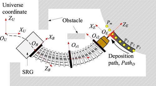
Driven by the requirements, an SRG-based DED technology is proposed that integrates a soft robot system and a DED system, as shown in . The main ideology is to replace the rigid shell of a classical weld gun by using a soft robotic manipulator. In this way, the deformation of the gun shape can be precisely controlled by a computer, enabling the steering of the end effector to adapt to complex spatial constraints. Due to the variety of alternatives concerning both DED and soft robotic manipulators, the specific design of the SRG-based DED system followed certain principles.
(i) Tendon-driven actuation. Similar to the structure of the human hand, the major characteristic of a tendon-driven actuator is that heavy driving units can be kept away from the end actuation units, which enables the compact design of the soft gun shell. Since the driving force and control are transmitted through the tendons, this mechanism reduces the mess and inertia of the robotic weld gun and performs high dexterity. Although tendon-driven actuation is less compliant than pneumatic or hydraulic counterparts, the motion of GMA-DED is usually characterised by constant and low speed with a constant workload. Dynamic performance would not be a major issue for controlling the deformation of gun shape, and requirements can be satisfied by the state-of-the-art solutions.
(ii) Constant (flat) voltage power source. GMA-DED usually operates with a DC power source that performs a constant (flat) feature concerning the relationship between voltage and current. When the wire is fed from the nozzle with a constant speed, the arc length can adjust itself, maintaining a stable process of deposition due to the external characteristic of a flat voltage power source [Citation34]. Accordingly, this type of power source could reduce the influence of fluctuations caused by tendon-driven control of gun shell deformation, such as the vibration generated by the acceleration and deceleration of the SRG motion, the axial shrinkage generated by tendon-driven steering, and the deviation of motion trajectory caused by friction between tendon and soft gun shell.
(iii) Utilise arc force and drop impact to enhance bead formation. When the substrate surface of deposition is other than flat, the gravity of the molten pool causes the tendency to collapse, making poor bead formation. Unlike other metal AM alternatives, the GMA-DED process features a complex force field that acts on the molten pool, including arc pressure, droplet impact, and surface tension. Manipulation of the forces by changing the deposition gesture of the weld gun and deposition parameters (e.g. voltage, current) can inhibit the collapse effect of the molten pool and enhance the quality of bead formation [Citation35,Citation36]. In this way, omnidirectional deposition of metal can be achieved.
(iv) Coaxial feeding of wire and gas. Another benefit of the GMA-DED is that the wire and gas are coaxially fed from the weld gun, and the wire is set as a consumable electrode. It means that the melting of material can be kept at the gun centre and is independent of the deposition direction. This is also a crucial principle to enable omnidirectional metal deposition when the SRG is ordered to follow a complex path within a narrowed workspace. In addition, using consumable electrodes is the precondition for maintaining the stability of the deposition process when using the constant voltage power source.
Figure 1. The novel soft-robotic-gun (SRG)-based DED technology.
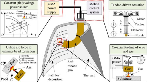
It can be seen that the integration of a tendon-driven actuation system and GMA-DED system allows omnidirectional deposition of metal. The characteristics of both systems complement each other concerning the adaptability to curved and inclined surfaces, the stability of metal and heat transfer, and the flexibility of motion in a complex path. Therefore, this specification of SRG-DED is a promising solution that can satisfy the requirements of additive manufacturing within space constraints.
2.3. Hardware design and implementation
A prototype system was designed and implemented to validate the concept of the SRG-DED technology. As shown in (a), the SRG comprises a soft robotic manipulator as the gun shell and the wire-gas-power supplement structure in the shell. The main body of the soft robotic manipulator consists of two segments. Every segment is made of a compression spring, which provides resilient force to perform shrinkage and steering motion in the case of a narrowed environment. The two compression springs are fixed with three disk-like metal sheets, and the far-end sheet from the nozzle is set to a frame. Six tendons drive the motion of the soft robotic manipulator, and each is independently controlled by a step motor, providing six degrees of freedom of motion. Holes are produced on the disk-like sheets with an even distribution, allowing the tendons to pass and fix. The number of holes on the sheets are 3, 6, and 6, respectively, in the order of their distances to the nozzle. Accordingly, the motion of every segment is controlled by three tendons, which are placed at an interval of 120°. The above sets allow the SRG to move relative to the frame centre.
Figure 2. The SRG-DED system: (a) Structure; (b) A prototype.
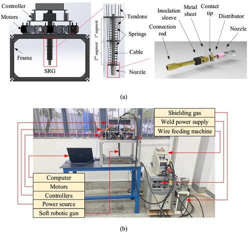
The wire-gas-power supplement structure is adapted from a classical GMA weld gun consisting of a GMA cable, a connecting component, and a nozzle. The GMA cable enables coaxial feeding of wire, gas, and weld power during deposition. The structure of the connecting component is detailed in (a). The rear end of the connecting rod is wrapped by the copper wire of the cable and fastened by a metal clamp. The joint of the cable and the connecting component is covered by a rubber sheath, preventing the shielding gas from leaking and insulating the strong and weak electricity. The connection rod is linked with the insulation sleeve and contact tip by thread. The size and weight of the connecting component and the nozzle are minimised and compacted to reduce the workload of the SRG while maintaining the laminar flow of the shielding gas.
According to the design structure, a prototype system was implemented, as shown in (b). The motor was 57BYG250B, and its torque was 1.2N·m. The planetary gearbox with a reduction ratio of 4 was selected to increase torque. The control board was Arduino Mega2560 with 54 digital IO pins. MP1584EN (9 V) step-down module was chosen according to the required voltage of the control board. The serial number of the weld machine was Panasonic YD-350FR2. Copper-coated low-carbon wire with a diameter of 1.2 mm was utilised as the feed material. The shielding gas was 95%Ar and 5%CO2 with a flow rate of 20 L/min. An aluminum plate was installed at the top of the frame, on which motors are circumferentially fixed. The tendons were connected with the speed reducers after passing through fixed pulleys. The total length of the SRG was 300 mm, and that of every segment was 150 mm. In the implemented SRG, the diameters of the tendon connection on metal sheets were 40 , 48 , and 56 mm, respectively, which reduces the axial compression of the spring when the SRG bends.
It can be seen that the design and implementation of the SRG system followed the principles and satisfied the requirements of omnidirectional deposition of metal within a narrowed environment. Since the SRG has to place a wire-gas-power supplement structure inside, the hollow structure cannot contain any supportive stand for improving the stiffness of the manipulator. Details about the kinematics modelling and trajectory planning are introduced in the next sub-sections.
3. Kinematics modelling of the SRG
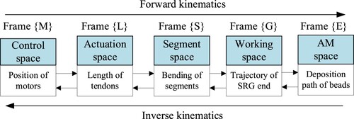
The Kinematics of the SRG is the basis of motion control and trajectory planning, and forward kinematics and inverse kinematics can be distinguished. presents the multi-level kinematics of the SRG-DED system. The forward kinematics refers to the mapping relationship from the control space to the AM space, whereas the inverse kinematics refers to that of the opposite direction. That is, the motion of motors initiates the length changes of tendons, which further causes the bending of segments to change the pose of the SRG end. In the context of AM, the inverse kinematic model should be used to find the control variables of the motors according to the required deposition path of beads. Models of both forward kinematics and inverse kinematics are detailed as follows.
Figure 3. The multi-level kinematics of the SRG-DED.
3.1. Forward kinematics
The forward kinematic problem of the SRG cannot be solved by the classical kinematic modelling methods built based on joints, such as the Denavit-Hartenberg method [Citation37]. This paper applied the piecewise constant curvature (PCC) method to approximate the pose of the SRG end, which is commonly used for modelling continuum robot arms [Citation14,Citation38]. The PCC method hypothesizes that a continuum robot arm can be decomposed into several continuously connected pieces. Suppose a piece is relatively small in length. In that case, it can be abstracted to an arc with a constant curvature, as shown in . Variables of a piece can be identified as: the curvature of arc , the bending plane angle
and the length of the arc
.
Figure 4. Kinematic model of the soft robotic gun.
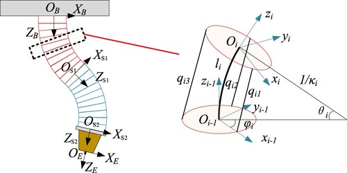
According to the geometric relationship presented in , the transformation from the coordinate system to the coordinate system
can be decomposed into successive sub-transformations, including: (i) a rotation about
-axis by
, (ii) a rotation about new
-axis by
, (iii) a translation along with the new
-axis about
, (iv) a rotation about new
-axis by
, and (v) a rotation about new
-axis by
[Citation39]. The sub-transformations can be represented by:
(1)
(1)
(2)
(2)
(3)
(3)
(4)
(4)
(5)
(5) where,
is centre angle corresponding to arc
, and
is radius of the curvature of arc
.
Accordingly, the homogeneous transformation matrix can be noted as:
(6)
(6) The transformation matrix from the base coordinate system {B} to the end of the second segment {S2} can be noted as:
(7)
(7) where N is the number of arcs, in this work, the two segments of the SRG were represented by 20 arcs.
Then, the mapping between the length of tendons and the parameters of arcs is:
(8)
(8)
(9)
(9)
(10)
(10) where,
is the length of two deformable segments,
,
,
are the length changes of three tendons respectively, and
is the length change of centre line;
is radius of circle formed by tendons.
According to the design of the SRG, the relative relationship from the origin of {S2} to the end of SRG, i.e. the tip of the fed wire, does not change. The transformation matrix can be noted as:
(11)
(11) where
refers to the distance from the centre of the last metal sheet to the tip of the fed wire. Accordingly, the forward kinematic model of the SRG can be noted as:
(12)
(12)
3.2. Inverse kinematics
The objective of the inverse kinematic model is to obtain the lengths of tendons when an end pose of the SRG is designated. The challenge of inverse kinematic modelling comes from the fact that the control of tendons may cause axial shrinkage of the SRG, which generates errors in calculation. The pseudo-inverse Jacobian method is usually used in the literature for modelling soft manipulators [Citation40]. However, the accuracy of the pseudo-inverse Jacobian method decreases significantly as the degree of freedom increases. Another disadvantage of this method is that computing the inverse Jacobian matrix is time-consuming, making it difficult to apply in real-time motion trajectory planning. In this work, the backbone curve method (BCM) [Citation41] was selected to approximate the lengths of tendons to reduce the amount of computation. The workflow of the BCM includes three steps: (i) calculating the backbone curvature function of the SRG, (ii) calculating the pose of segments based on the backbone curvature function, and (iii) calculating the length changes of tendons.
The backbone curvature function of the SRG can be represented by:
(13)
(13) where,
is coordinates of points in the backbone curvature,
is the length of the backbone curvature;
is the tangent vector of the backbone curvature at
,
is the normalised length of the backbone curvature and
.
A backbone curvature can be parameterised by and
.
is the angle between the projection of
on the XOY plane and the y-axis.
is the angle between the projection of
on the XOY plane and
.
and
can be noted as:
(14)
(14)
(15)
(15) where,
,
and
are the modal participation factors, and
,
,
, and
are angles at the beginning and end of the backbone curvature.
Accordingly, the vector can be described by
and
. Then,
(16)
(16) The backbone curvature can be represented by:
(17)
(17) To calculate the modal participation factors, the derivation of the backbone curvature function in time can be noted as follows:
(18)
(18)
(19)
(19) The modal participation factors can be obtained by Newton’s method, and the iterative formula is:
(20)
(20) where
is the convergence coefficient,
is the iteration number,
is the solution of the current state in iteration, and
refers to the set value.
Since the Jacobian matrix is not full rank,
is a generalised inverse matrix. The modal participation factors are considered the final result when the distance between the current solution and the set value is lower than a threshold. Then, the tendon variable can be calculated using EquationEquation (12)
(12)
(12) and EquationEquation (17)
(17)
(17) .
3.3. Trajectory planning of the SRG
The trajectory planning of the SRG has to track the required deposition paths of AM with high accuracy to maintain deposit consistency in geometry and performance. When the SRG is working in a narrow environment, trajectory planning has to consider the feasibility of task execution and avoid potential collisions between the SRG and the working environment. A typical scenario is shown in . If the deposition process is focused on only, then the SRG is required to execute the deposition path in an environment where obstacles exist. The deposition path can be decomposed into
successive points, namely
, while the volume of the obstacle is represented as
.
Figure 5. Planning motion trajectory of the SRG under space constraints.
Accordingly, the objective of the trajectory planning is to calculate:
(21)
(21) where
,
refers to the length of a tendon.
Subject to:
(22)
(22) where
refers to the swap volume of the SRG during deposition.
can be calculated using the inverse kinematic model:
(23)
(23)
can be known from the backbone curvature model:
(24)
(24) Although Equations Equation(21)
(21)
(21) –Equation(24)
(24)
(24) provides a feasible solution for trajectory planning, the calculation of tendon lengths using the inverse kinematic model concerning all decomposed positions on the path is time-consuming. The BCM contains an iterative computation mechanism for obtaining the backbone curvature function of the SRG. For this reason, the trajectory planning of the SRG applied an integrative solution that combines the inverse kinematic model and the resolved motion-rate mechanism [Citation42]. That is, the initial state of the SRG is calculated using the pose of the start-arc position, i.e.
, while the rest of the states are computed in the segment space using the resolved motion-rate method. A detailed explanation is presented as follows.
According to EquationEquation (12)(12)
(12) , the forward transformation matrix of the SRG is:
(25)
(25) where,
,
and
are functions of tendon length changes.
The end position of SRG can be noted by:
(26)
(26) The relationship between the speed of the SRG end and the speed of tendon motion can be obtained by taking the first derivative on both sides of EquationEquation (26)
(26)
(26) :
(27)
(27) where, the Jacobian matrix
is:
(28)
(28) Therefore, the tendon length changes and the Jacobian matrix of the subsequent position can be iteratively calculated using the following equations:
(29)
(29)
(30)
(30) In this way, the change of the tendon variables is solved using the velocity of the SRG end and the Jacobian matrix. After the initial state of the SRG is computed, the tendon variable and Jacobian matrix should be updated until the last position of the path is reached.
3.4. Software implementation
According to the above-presented mechanisms, a software was implemented for controlling the SRG on a computer with i7-9750H CPU and 8.00 GB RAM. Motor control was realised using a programme written in the Arduino IDE environment. Arduino RTOS was used to resolve commands sent from the computer and implement the multi-task control of motors. The calculation of inverse kinematics and trajectory planning was accomplished by Matlab. Control commands of motors were sent to the Arduino board via serial port communication.
The workflow for planning the trajectory of the SRG system is shown in . After setting the expected position and orientation of the first point on the trajectory, the algorithm utilises the inverse kinematic model for obtaining the initial state of the SRG on the deposition trajectory. To this end, the modality functions, i.e. Equations Equation(14(14)
(14) –Equation15)
(15)
(15) of the backbone curvature, were constructed, and the modal participation factors were solved to obtain the backbone curve function, i.e. EquationEquation (13)
(13)
(13) . Then, the section coordinates of the SRG can be calculated using the bisection method. The length changes of tendons for the start position of the trajectory were solved according to the arrangement of tendons and the section coordinates. The tendon length changes were transferred to the angles of the motors for control.
Figure 6. Workflow for trajectory planning of the SRG.
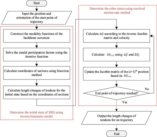
Having the initial state of the SRG, the trajectory planning is performed in the actuation space, in which the changes of the tendon variables were solved according to the required motion velocity of the SRG endpoint. The calculation mechanism followed the procedure of Equations Equation(25)(25)
(25) –Equation(30)
(30)
(30) . It is worth mentioning that the length changes of the driving tendons are obtained simultaneously. Since the posture relationship between the end of the SRG and the two segments is fixed and unbendable, the pose of the SRG end cannot be directly used to solve the expansion of the tendons. The backbone curve obtained at every point on a trajectory is the attitude of the SRG after the end of SRG is transformed to the end of the two segments. The iteration of the calculation proceeded until the end point of the trajectory was reached. Finally, the algorithm recorded the tendon length changes over the successive points,
, and computed the control commands of the corresponding motors.
4. Validation of the SRG-DED
The validation work contained both internal validation and external validation. Internal validation was employed to confirm the effectiveness of the implemented software and hardware system. In contrast, external validation was conducted to validate the applicability of the SRG-DED system for AM applications. Accordingly, the validation of kinematic modelling and trajectory planning algorithms was carried out by simulation. The actual performance of the SRG-DED system was validated by measuring the positioning accuracy and using the system in a practical deposition task.
4.1. Validation of the kinematic model
The purpose of internal validation was to obtain the motion capability of the implemented prototype system, forming a basis for determining whether a designated trajectory can be achieved. Since the end position of the SRG is a projection of a set of tendon variables, the boundary of the tendon variables was first defined from the parameters of the hardware devices before kinematic modelling could be validated.
The maximum output torque of the employed motor was 1.2 N·m, while the reduction ratio of the reducer was 4. Then, the maximum torque of a tendon was 4.8 N·m. The bending of the spring shell resisted the shrinkage of a tendon. The output torque can be used to define the maximum length that a tendon could shrink. The moment of spring can be computed by:
(31)
(31) where
is the elasticity modulus of the spring and
;
is the radius of curvature of the torsion;
is the moment of inertia, which can be computed by
;
is the radius of the spring wire and
= 1.5 mm. According to the size of the parts at the shaft of the reducer, it can be obtained that the maximum value of
is 7.68 N·m. Then, the maximum radius of curvature can be calculated as 106.7 mm. The corresponding length change of a tendon is 33.7 mm.
Based on the range that the tendon length can change, the theoretical workspace of the SRG can be specified based on the implemented forward kinematic algorithm. The computation considered a combination situation of different length changes about the six tendons. Thus, the workspace was determined by randomly selecting the length change of tendons varying from 0 mm to 33 mm with an increment of 11 mm. The result is shown in , in which 4096 situations were calculated. Every point represents the end position of a combination. The base of the SRG is placed at the origin of the coordinate system.
Figure 7. Work space of the SRG prototype system: (a) Three-dimensional view; (b) Projection on the XOY plane; (c) Projection on the XOZ plane; (d) Projection on the YOZ plane.
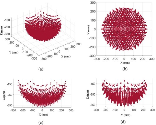
According to the simulation results, the forward kinematic model is confirmed, and the assumption of omnidirectional deposition by using the SRG is realised. It can be seen that the workspace covers the surface of a lower hemisphere, which identifies that the SRG can accomplish a curved path in 3D space by synthesising the tendons. In particular, the projection of the workspace on the XOY plane appears to be a centrosymmetric circle approximately. It means the six tendons jointly offer the isotropic motion performance in space. Thus, the motion of the two-segment structure SRG towards different directions in the workspace is equivalent, e.g. clockwise and anti-clockwise motion.
In addition, it can be seen from (c) and (d) that most points are distributed at the bottom half of the space, while a sparse distribution of points at the top half can be observed. As the length changes of tendons are evenly set, a change increment for a relatively large bending angle resulted in a greater response than that for a relatively small angle. This attribute implies a non-linear behaviour for motion control. The different points distributions between (c) and (d) arises from the fact that (c) provides a view between two adjacent driven tendons, whereas (d) offers a view from one driven tendon. Besides, the reason for the asymmetrical shape of (c) is that the two adjacent driven tendons are fixed on the different segments. It is worth mentioning that the workspace shown in is not a complete set, while there might be other positions that can be reached by the SRG end. The presented range was considered as a reference for planning the motion trajectory.
4.2. Validation of the trajectory planning algorithm
The programmed algorithms were tested in the simulation environment to validate the effectiveness of the trajectory planning mechanism. Since various types of paths may be involved for AM, three typical paths were considered in the simulation test, including a linear path and two circular paths. The positions that define the three paths are shown in . The second path is on a vertical plane (x = 71), while the third is on a horizontal plane (z = −284). The speed of deposition was set as 5 mm/s. The maximum speed of tendon stretching set by the prototype system was 4.0 mm/s. The base of the SRG was placed at [0,0,0]. Since the implemented SRG structure does not have redundant degrees of freedom, the pose of SRG was neglected during computation.
Table 1. Experimental setup of the trajectory planning simulation.
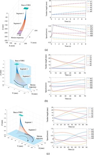
The results of trajectory planning are shown in , including the positions of segments and the SRG ends at a set of sampling positions, as well as the calculated tendon lengths and the speed of tendon stretching over time. To reduce the computational amount, the step increments of the paths were 2.25 , 12 , and 15 mm, resulting in 20, 30, and 30 sampling points, respectively. It can be seen that the implemented algorithms are feasible for computing poses of the SRG according to the required deposition paths. The tendon lengths and speeds are within the defined scope of the prototype system, which confirms the validity of the tendon control sub-system. In addition, the speed of tendon stretching is smoothly changing in all three cases, and no sudden increase or decrease can be found. This means the trajectory planning algorithm would not cause significant inertial forces when using the SRG in actual depositions. All the above phenomena evidenced that the implemented trajectory planning algorithms satisfy the requirements and can be used for AM scenarios.
Figure 8. Simulation results of trajectory planning: (a) A linear trajectory; (b) A circular trajectory on a vertical plane (x = 71); (c) A circular trajectory on a horizontal plane (z = −284).
In the proposed trajectory planning mechanism, the inverse kinematic model and the resolved motion-rate mechanism were jointly applied to calculate tendon variables, which was supposed to increase the computation efficiency. Since the resolved motion-rate mechanism is an approximate approach, a comparison between the results obtained using the inverse kinematic model and those by the proposed hybrid method is shown in . The consistency to designed path (CDP) was used as a factor for evaluating how much the calculated trajectory is the same as the planned path, which can be calculated by:
(32)
(32) where,
indicates a designed position on the path,
refers to the calculated position of the same,
represents the distance between the two positions.
Table 2. Comparing the inverse kinematic model and the proposed trajectory planning method.
It can be seen that the proposed mechanism significantly reduced the computational time spent on obtaining the tendon variables. The inverse kinematic model method has to repetitively calculate the modal participation factors in the backbone curvature function using an iteration mechanism at every sampling point on the path, resulting in a huge computational amount. In contrast, the proposed method only needs to update the Jacobian matrix according to the speed of motion, which facilitates the reduction of computation time.
In addition, an interesting phenomenon was that the CDP error of the proposed method was smaller than the inverse kinematic model. Because the BCM for obtaining the inverse kinematic model is an approximation solution, as represented by EquationEquation (20)(20)
(20) . The accuracy of modal participation factors is associated with the time of iteration. In the implemented software, the threshold of
was set to 0.3 mm, which accords with the CDP results. On the other hand, the resolved motion-rate mechanism employs the vector from the position of the previously calculated sampling point and the designated position of the next as the speed of motion for updating the Jacobian matrix. This mechanism is independent of the accuracy of the inverse model, which naturally minimises the errors of trajectory planning. Therefore, the proposed method was effective for planning the motion trajectory of the SRG.
4.3. Measurement of the SRG accuracy
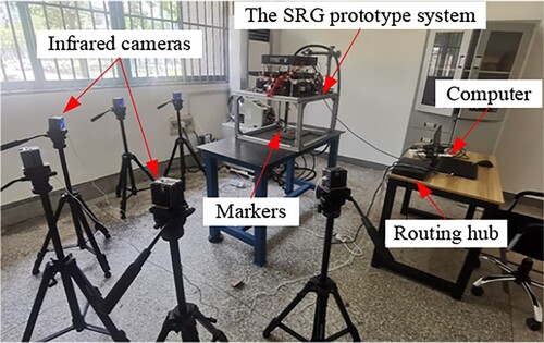
To support deposition for AM applications, the actual performance of the implemented SRG system has to be validated. To this end, the accuracy of the SRG system was measured by a motion-tracking system. The experimental setup for the measurement is shown in . The OptiTrack® Prime X13 platform was applied, which employed six infrared cameras to catch the position of 4 markers stuck on the gun. The position of the gun was calculated using the positional information of the markers. Data recording and calculation were achieved using the OptiTrack® Motive software. The measurement accuracy of the platform was 0.3 mm.
Figure 9. Experimental setup for measuring the accuracy of the SRG
In the performed tests, 30 positions were designed and evenly distributed to the workspace of the SRG. For every position, both absolute error and repeated error were calculated. Absolute error was the distinction between a theoretically calculated position using the forward kinematic model and the measured one. The repeated error was defined as the deviation from a previously taught position to a repetition of the same by playing back previously stored positions of motors. The average value of the three test results was considered the final measurement result. The results are shown in . ,
and
refers to the tendon length changes of the first segment, while the rest refers to those of the second segment.
Table 3. Position accuracy measurement results of the soft robotic gun (mm).
It can be seen from the results that the absolute error ranges from 2.4 mm to 130.3 mm, while the repeated error ranges from 0.2 mm to 6.1 mm. Both types of positioning error monotonously rise as the length change of the tendon increases. It means that the positioning accuracy decreases with an increasing degree of bending. In addition, when multiple tendons are controlled, the absolute accuracy is dramatically reduced. The motion of the tendons influences each other, forming a coupling effect of actuation. Furthermore, due to the inherent bending of the weld cable in the SRG, the accuracy of every tendon actuation is different. According to the work presented by Ščetinec et al. [Citation43], the maximum allowable deviation of wire arc DED is 3.5 mm. For this reason, the repeatability error at the bottom of the workspace is acceptable for conceptual validation of the implemented prototype.
The reason for the errors can be analysed from the following aspects. At first, the kinematic model established in Chapter 3 is an idealised model in which the influence of the stiffness of the weld cable was not considered. Since the weld cable has to convey wire, gas, and power for AM, the wire feeding tube, sealed rubber tube, and covering copper net all resist the bending of SRG during the motion control. The resistance requires extra force provided by the motors. In the implemented prototype, step motors were applied, which may lose a step when the inertia of the SRG movement exceeds the self-locking force. In particular, the deformation of the weld cable generated a giant elastic force when the bending angle increased significantly. When the SRG is forced to bend, the friction between the tendons and the spring becomes significant, which is also opposite to the driving force of the motor. The above two factors caused a distinction between the actual rotation angle of the motors and the commanded pulse, resulting in a dramatic error in the absolute positioning accuracy.
Another error source comes from the motion coupling of the two segments when multiple tendons are controlled simultaneously. In addition to the bending motion of SRG, the length changes of the tendon also trigger a shrinkage of SRG, which further causes changes in the relative distance from the metal sheet to the motor of the rest of the tendons. In this situation, the rest of the tendons may be loose or stretch if the corresponding motors are not controlled adaptively. For this reason, the control of tendons belonging to different segments influences each other, which induces a great error between the actual length changes of tendons and the expected values. This is why multi-tendon control performed with relatively low accuracy in absolute positioning. Last but not least, geometrical errors may be generated from the machining and assembly process of the prototype system, such as the position of holes on the metal sheets, the positions of pulleys, and the length of springs, contributing to the final error of positioning.
It can be seen from that the length change of tendons (i.e. ,
, and
) belonging to the second segment is more influential to the repeated positioning error than those (i.e.
,
, and
) of the first segment. The main reason can be explained as the influence of the servo error of the step motors. Since the second segment is further from the base than the first segment, the arm of force applied to bend the second segment is greater. Bending the second segment requires a greater moment from the motors than the first segment, which was prone to generate accidental motor servo errors. In addition, an opposite phenomenon can be observed concerning the influence of the two segments on the absolute positioning error. Because
,
, and
tendons were used to control the position of the middle metal sheet. During the bending of the first segment, the second segment cannot remain straight due to gravity. The free deformation of the second segment caused additional spatial deviation from the theoretical value. The tendons of the second segment, i.e.
,
, and
, were linked to the bottom metal sheet, which is closer to the SRG end. The nozzle is rigid, which had a smaller influence on the absolute positioning error.
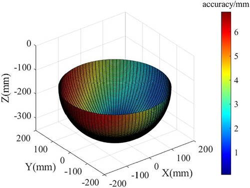
Therefore, the accuracy measurement results provide a reference basis for applying the SRG system in AM applications and for further improving the SRG structure to achieve a higher accuracy. Concerning the results of the repeated positioning, the error maintained a relatively low value when the length of tendons changed within an acceptable range. Since the absolute error is far more significant than the requirement of AM applications, the repeated positioning error was considered when designing AM paths. According to the obtained data, the repeated positioning accuracy of the SRG in the working space is drawn, as shown in . When x-axis belongs to [−87.1 mm, 160.0 mm], y-axis belongs to [−140.0 mm, 200.4 mm], z-axis belongs to [−348.5 mm, −226.2 mm], the repeated positioning error is smaller than 2 mm. The specified range was considered in the AM case study, and the details will be presented in the next section.
Figure 10. Repeated positioning accuracy of the SRG.
4.4. Case study
4.4.1. Case 1: a complex path
The first case study was designed in which the SRG system was employed to deposit a complex path. The setup of the case study is presented in . As shown, a path was set on a flat substrate with an inclination angle of 20°. According to the result of the accuracy measurement, a closed deposition path was established within the range where the accuracy of repeated positioning is superior to 2 mm. The path consists of three segments, including two linear segments (i.e. and
) and a circular segment with an angle of 2
/3 (i.e.
). The path starts and ends at point A. The lengths of the segments were set as 25, 25, and 52.3 mm, respectively. The coordinates of the segments are presented in .
Figure 11. Experimental setup of the case study: (a) Initial state; (b) Deposition path.
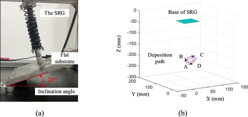
Table 4. Positions of points on the deposition path.
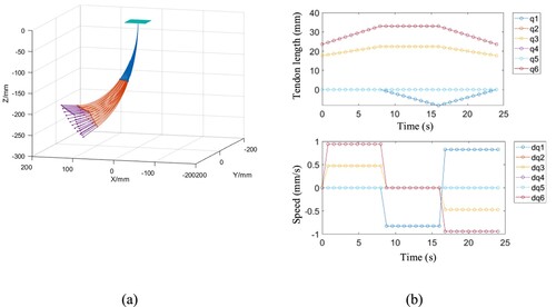
The weld current, voltage, and wire feeding speed were set as 145 A, 21.5 V, and 3.6 m/min, respectively. The speed of deposition was set to 5.7 mm/s. The material of the substrate was low-carbon steel Q235B, while that of the feeding wire was ER70-6. The diameter of the fed wire was 1.2 mm. The shielding gas was 95% Ar and 5% CO2 with a flow rate of 18 ± 0.5 L/min. The implemented trajectory planning algorithm was used to calculate the lengths of tendons, which is the reference for motor control. The result of trajectory planning is shown in . Due to the high coupling of position and orientation of the SRG, the gesture of the weld gun to the substrate was not specified. In addition, since the dynamics model of the SRG was not considered in controlling the motion of the SRG. The acceleration and deceleration involved in the start and stop periods may generate fluctuations. To avoid the influence of the start period, the deposition path was extended by 15 mm before point A.
Figure 12. Result of trajectory planning: (a) Shape of the SRG; (b) Speed of motion.
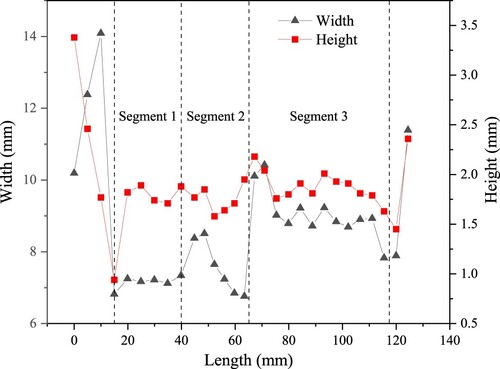
During the deposition process, the SRG moved at a constant speed during operation and ran smoothly. The arc maintained a stable state, and no interruption was observed. The appearance of the deposited path is shown in (a). The overall appearance of the path is relatively good, consistent with the experimental settings. The pre-set deposition trajectory of the SRG was realised, which proves the feasibility of using the SRG to achieve a complex deposition path. A three-dimensional scanner with an accuracy of 0.05 mm was used to measure the geometries of the formed deposit. The results are shown in (b). The measured geometries of the deposition path are presented in . A significant defect can be observed at the arc distinguishing section, resulting in defects in the overlapping of beads. In addition, geometrical deviations are generated at the place where the SRG needs to change the direction of deposition. This is because the change of deposition direction requires a sudden acceleration. The soft shell of the SRG was made of spring, which generates fluctuations when an acceleration is applied. A sudden increase in width can be observed at the corners.
Figure 13. The deposited path: (a) the appearance; (b) three-dimensional measurement.
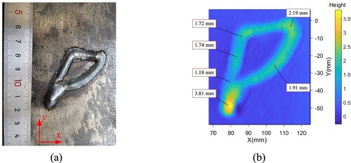
Figure 14. Measured geometries of the deposited bead.
The results of the case study confirmed the applicability of the implemented SRG system in the context of AM. However, several limitations were implied. On the one hand, the motion controlling of the SRG was realised based on the results of trajectory planning, while the dynamic responses of the SRG were neglected. Consequently, slight fluctuations were observed on the SRG during deposition, leading to errors in both width and height. Accordingly, the speed curve of the SRG motion during the acceleration and deceleration processes has to be articulated to ensure a constant deposition geometry, which is the basis for using the SRG system in fabricating a complex part. On the other hand, a drawback of the tendon-driven structure in nature is that a tendon cannot push forward. Since the lengths of the tendons are highly coupled, inaccurate control of tendons may influence the length of the rest of the tendons, making the end pose unpredictable. Therefore, it is necessary to control all tendons synthetically to enhance positioning accuracy. These limitations deserve further investigation.
4.4.2. Case 2: a thin-walled component
The second case study uses the implemented prototype system to deposit a multi-layer component within a constraint space. Since inconsistent bead formation significantly influences the quality of multi-bead deposition in a layer, a thin-walled component was designed in the case study. All deposits were set within the range of repeated positioning accuracy superior to 2 mm. As shown in , the SRG was controlled to insert into a steel pipeline and deposit onto a substrate attached to the pipeline wall. Due to the limitation of workspace, the component contained 6 layers, and every layer has two linear segments (i.e. and
) with the length of 50 and 30 mm, respectively. The angle between the two segments was 60°, and the height of each layer was 1.5 mm. The result of trajectory planning is shown in (b). The current, voltage, and wire feeding speed were set to 90A, 19.6 V, and 2.1 m/min, respectively. The deposition speed was set to 5 mm/s, while the other settings were the same as in the above case study.
Figure 15. Case study 2: (a) experimental setting; (b) result of trajectory planning; (c) actual deposition process; (d) the deposited component.
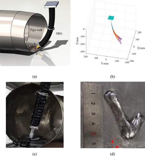
The deposited component is presented in (d). As shown, the overall appearance is relatively good and is consistent with the experimental settings. Neither crack nor pore can be observed, confirming the positioning accuracy of the SRG-DED system. The highest point of the component is located at the intersection of the two segments. This is because the two segments intersect at an acute angle, and deceleration and acceleration periods were involved, causing lower deposition speed on average and additional deposition amount at the corner. The multi-layer deposition within a pipeline environment confirms the assumption of the research. That is, integrating a soft robotic manipulator and GMA power source facilitates metal additive manufacturing with space constraints.
Due to the limitation of the work range, the implemented prototype can only complete a component-level deposition. Part-level validation will be considered as near-future research by integrating the SRG-DED system with a 6-axis industrial robot. In addition, the positioning error of the SRG was caused by a synergic effect of multiple influencing factors, including the imperfection of the theoretical model, the servo error of the step-motor, the friction of tendons, and the manufacturing error of the implemented prototype. Mitigation measures and optimisation schemes will be focused on for enhancing positioning accuracy and improving deposition quality. Last but not least, the forming consistency of the deposited bead is strongly influenced by the flow behaviour of the molten pool, which is very sensitive to the inclination angle of the substrate, deposition parameters, and motion parameters of the weld gun. The developed kinematic model and motion planning algorithm neglected the dynamic behaviours, and fluctuations were generated during the deposition of the SRG. Accordingly, controlling the stability of the molten pool by optimising deposition parameters is a recommended research topic.
5. Conclusions
This paper presented a soft robotic gun (SRG)-DED technology for omnidirectional metal deposition within a narrowed environment. Both requirements and design principles were proposed, based on which a prototype system was implemented for conceptual validation. Major conclusions can be drawn as follows.
The designed SRG-DED prototype integrates the advantages of GMA-AM and tendon-driven continuum manipulator. The characteristics of both systems complement each other, which enhances the flexibility of metal deposition towards varying directions and the adaptability of AM within a narrowed environment.
The proposed trajectory planning algorithm uses the backbone curve method and the resolved motion-rate mechanism for calculating the tendon variables of sampling positions on a path, improving the computational efficiency and enhancing trajectory tracking accuracy to 0.1 mm.
A motion capture system was employed to measure the positioning accuracy of the SRG-DED prototype system. The repeated positioning accuracy ranges from 0.2 mm to 6.1 mm within the system work range, allowing a continuous deposition of GMA-AM.
The prototype system deposited a complex path on an inclined surface and a thin-walled structure as validation. During the deposition process, the arc remained stable, and no interruption was observed, which approves the feasibility and applicability of the SRG-DED prototype system for AM applications.
Author contributions
Dr. Yongzhe Li initialised the research and conceived the theory. Ms. Wenqi Zhong contributed to the implementation and experimentation. Dr. Xinlei Li and Dr. Qinghua Wang helped with data processing. Dr. Xianjun Pei, Dr. Xiaochao Liu and Prof. Yijun Zhou were responsible for conceptual validation. Dr. Hao Yi revised the paper. Prof. Xiaoyu Wang supervised the research. All authors have read and agreed to the published version of the manuscript.
Acknowledgement
The authors would like to thank Mr. Jinlong Zhao and Suzhou Oufeier Intelligent Technology Co., Ltd for their support.
Disclosure statement
No potential conflict of interest was reported by the author(s).
Data availability statement
The data presented in this study are available on request from the corresponding author.
Additional information
Funding
References
- Armstrong M, Mehrabi H, Naveed N. An overview of modern metal additive manufacturing technology. J Manuf Process. 2022;84:1001–1029. doi:10.1016/j.jmapro.2022.10.060
- Kanishka K, Acherjee B. A systematic review of additive manufacturing-based remanufacturing techniques for component repair and restoration. J Manu Process. 2023;89:220–283. doi:10.1016/j.jmapro.2023.01.034
- Liu H, Wang S, Chen H, et al. Drop and hump behaviors in robotic arc-directed energy deposition with vertical position. Addit Manuf. 2024;82:104049. doi:10.1016/j.addma.2024.104049
- He T, Yu S, Shi Y, et al. Forming and mechanical properties of wire arc additive manufacture for marine propeller bracket. J Manuf Process. 2020;52:96–105. doi:10.1016/j.jmapro.2020.01.053
- Xiong J, Wen C. Arc plasma, droplet, and forming behaviors in bypass wire arc-directed energy deposition. Addit Manuf. 2023;70:103558. doi:10.1016/j.addma.2023.103558
- Lehmann T, Rose D, Ranjbar E, et al. Large-scale metal additive manufacturing: a holistic review of the state of the art and challenges. Int Mater Rev. 2022;67(4):410–459. doi:10.1080/09506608.2021.1971427
- Kazanas P, Deherkar P, Almeida P, et al. Fabrication of geometrical features using wire and arc additive manufacture. P I Mech Eng Part B: J Eng Manu. 2012;226(6):1042–1051. doi:10.1177/0954405412437126
- Aprilia A, Wu N, Zhou W. Repair and restoration of engineering components by laser directed energy deposition. Mater Today Proc. 2022;70:206–211. doi:10.1016/j.matpr.2022.09.022
- Rus D, Tolley M. Design, fabrication and control of soft robots. Nature. 2015;521(7553):467–475. doi:10.1038/nature14543
- Seleem I, El-Hussieny H, Ishii H. Recent developments of actuation mechanisms for continuum robots: a review. Int J Control Auto. 2023;21(5):1592–1609. doi:10.1007/s12555-022-0159-8
- Schmitt F, Piccin O, Barbé L, et al. Soft robots manufacturing: A review. Front Robot AI. 2018;5:84. doi:10.3389/frobt.2018.00084
- Gupta U, Qin L, Wang Y, et al. Soft robots based on dielectric elastomer actuators: A review. Smart Mater Struct. 2019;28(10):103002. doi:10.1088/1361-665X/ab3a77
- Yasa O, Toshimitsu Y, Michelis M, et al. An overview of soft robotics. Annu Rev Control Robot Auton Syst. 2023;6(1):1–29. doi:10.1146/annurev-control-062322-100607
- Zhang J, Fang Q, Xiang P, et al. A survey on design, actuation, modeling, and control of continuum robot. Cyborg Bionic Syst. 2022;2022. doi:10.34133/2022/9754697
- Gunderman A, Collins J, Myers A, et al. Tendon-driven soft robotic gripper for blackberry harvesting. IEEE Robot Autom Lett. 2022;7(2):2652–2659. doi:10.1109/LRA.2022.3143891
- Dinakaran V, Balasubramaniyan M, Muthusamy S, et al. Performa of SCARA based intelligent 3 axis robotic soft gripper for enhanced material handling. Adv Eng Softw. 2023;176:103366. doi:10.1016/j.advengsoft.2022.103366
- Jolaei M, Hooshiar A, Dargahi J, et al. Toward task autonomy in robotic cardiac ablation: learning-based kinematic control of soft tendon-driven catheters. Soft Robot. 2021;8(3):340–351. doi:10.1089/soro.2020.0006
- Jiang S, Wang Y, Ju F, et al. A new fuzzy time-delay control for cable-driven robot. Int J Adv Robot Syst. 2019;16(2):172988141983501. doi:10.1177/1729881419835017
- Ataka A, Qi P, Liu H, et al. Real-time planner for multi-segment continuum manipulator in dynamic environments. 2016 IEEE International Conference on Robotics and Automation (ICRA) 2016:4080–4085. doi:10.1109/ICRA.2016.7487598
- Thuruthel T, Ansari Y, Falotico E, et al. Control strategies for soft robotic manipulators: A survey. Soft Robot. 2018;5(2):149–163. doi:10.1089/soro.2017.0007
- Bajo A, Simaan N. Hybrid motion/force control of multi-backbone continuum robots. Int J Robot Res. 2016;35(4):422–434. doi:10.1177/0278364915584806
- Li Z, Wu L, Ren H, et al. Kinematic comparison of surgical tendon-driven manipulators and concentric tube manipulators. Mech Mach Theory. 2017;107:148–165. doi:10.1016/j.mechmachtheory.2016.09.018
- Lai J, Lu B, Chu H. Variable-Stiffness control of a dual-segment soft robot using depth vision. IEEE-ASME Trans Mechatron. 2022;27(2):1034–1045. doi:10.1109/TMECH.2021.3078466
- Sapai S, Loo J, Ding Z, et al. A deep learning framework for soft robots with synthetic data. Soft Robot. 2023;10(6):1224–1240. doi:10.1089/soro.2022.0188
- Boettcher G, Lilge S, Burgner-Kahrs J. Design of a reconfigurable parallel continuum robot With tendon-actuated kinematic chains. IEEE Robot Autom Lett. 2021;6(2):1272–1279. doi:10.1109/LRA.2021.3057557
- Dong X, Raffles M, Cobos-Guzman S, et al. A novel continuum robot using twin-pivot compliant joints: design, modeling, and validation. J Mech Robot. 2016;8(2). doi:10.1115/1.4031340
- Xing Z, Wang F, Ji Y, et al. A structure for fast stiffness-variation and omnidirectional-steering continuum manipulator. IEEE Robot Autom Lett. 2021;6(2):755–762. doi:10.1109/LRA.2020.3037858
- Hitchin P. Getting innovation into decommissioning. Nucl Eng Int. 2017;62(751):20–23.
- Zhao X, Liu C, Dou L, et al. 3D visual sensing technique based on focal stack for snake robotic applications. Results Phys. 2019;12:1520–1528. doi:10.1016/j.rinp.2019.01.045
- Qin L, Tang Y, Gupta U, et al. A soft robot capable of 2D mobility and self-sensing for obstacle detection and avoidance. Smart Mater Struct. 2018;27(4):045017. doi:10.1088/1361-665X/aab393
- Lee J, Lee C, Kim D. Repair of damaged parts using wire arc additive manufacturing in machine tools. J Mater Res Technol. 2022;16:13–24. doi:10.1016/j.jmrt.2021.11.156
- Li X, Han Q, Zhang G. Large-size sprocket repairing based on robotic GMAW additive manufacturing. Weld World. 2021;65(5):793–805. doi:10.1007/s40194-021-01080-9
- Lant T, Robinson D, Spafford B, et al. Review of weld repair procedures for low alloy steels designed to minimise the risk of future cracking. Int J Pres Vessels Pip. 2001;78(11):813–818. doi:10.1016/S0308-0161(01)00094-1
- Yu Y, Xiong J, Chen Y, et al. Process stability control of corner structures in robotic gas tungsten arc additive manufacturing via arc sensing. J Manuf Process. 2023;101:156–170. doi:10.1016/j.jmapro.2023.05.076
- Yuan L, Ding D, Pan Z, et al. Application of multidirectional robotic wire arc additive manufacturing process for the fabrication of complex metallic parts. IEEE Trans Industr Inform. 2020;16(1):454–464. doi:10.1109/TII.2019.2935233
- Cai X, Lin S, Fan C, et al. Molten pool behaviour and weld forming mechanism of tandem narrow gap vertical GMAW. Sci Technol Weld Join. 2016;21(2):124–130. doi:10.1179/1362171815Y.0000000073
- Everett L, Driels M, Mooring B. Kinematic modelling for robot calibration. Proceedings of the 1987 IEEE International Conference on Robotics and Automation (ICRA). 1987:183–189. doi:10.1109/ROBOT.1987.1087818
- Han J, Han Z, Liu Z. Adaptive control for a constrained soft manipulator with prescribed performance. IFAC-PapersOnLine. 2020;53(5):524–529. doi:10.1016/j.ifacol.2021.04.198
- Webster R, Jones B. Design and kinematic modeling of constant curvature continuum robots: A review. Int J Robot Res. 2010;29(13):1661–1683. doi:10.1177/0278364910368147
- Peng J, Xu W, Liu T, et al. End-effector pose and arm-shape synchronous planning methods of a hyper-redundant manipulator for spacecraft repairing. Mec Mac Theory. 2021;155:104062. doi:10.1016/j.mechmachtheory.2020.104062
- Xu W, Mu Z, Liu T, et al. A modified modal method for solving the mission-oriented inverse kinematics of hyper-redundant space manipulators for on-orbit servicing. Acta Astronaut. 2017;139:54–66. doi:10.1016/j.actaastro.2017.06.015
- Simas H, Gregorio R. Smooth transition for collision avoidance of redundant robots: an on-line polynomial approach. Robot Comput Integr Manuf. 2021;72:102087. doi:10.1016/j.rcim.2020.102087
- Ščetinec A, Klobčar D, Bračun D. In-process path replanning and online layer height control through deposition arc current for gas metal arc based additive manufacturing. J Manuf Process. 2021;64:1169–1179. doi:10.1016/j.jmapro.2021.02.038