
 ?Mathematical formulae have been encoded as MathML and are displayed in this HTML version using MathJax in order to improve their display. Uncheck the box to turn MathJax off. This feature requires Javascript. Click on a formula to zoom.
ABSTRACT
Heat treatment free aluminum alloys have been developed for wire arc directed energy deposition (DED) large thin-walled components, but their further performance enhancement methods remain unexplored. In this study, laser shock peening (LSP) treatment was performed on wire arc DED Al-6Mg-0.3Sc components. The results show that LSP creates a gradient microstructure with submicro-grains near the surface. The effects of LSP on defects were quantified by quasi-in-situ CT, demonstrating a reduction in porosity by over 68% together with decreased size. Simultaneously, tensile strength increases by 39.5% to 295.8 ± 6.4 MPa with only a marginal loss of elongation, as compared to the as-deposited (AD) state. This was due to the accumulation of dislocations and continuous dynamic recrystallization lead to grain refinement, as well as the appearance of a triple heterogeneous microstructure. Therefore, this study offers a novel solution for manufacturing of high-performance heat treatment free large thin-walled components.
1. Introduction
The wire arc DED technology, with its advantages of rapid deposition, high material utilisation rate, and unlimited size, has been widely applied in the manufacturing of large-scale components [Citation1]. However, when using wire arc DED to manufacture aluminum components, especially large thin-walled structures, challenges such as low mechanical properties and numerous defects often arise [Citation2]. Scholars have attempted to address these challenges by selecting high strength aluminum alloys like 2XXX and 7XXX, which rely on heat treatment to enhance their mechanical properties [Citation3,Citation4]. Meanwhile, efficient and rapid method to enhance the mechanical properties of large components have also been documented. Some researchers have explored methods such as interlayer rolling [Citation5] and interlayer hammering [Citation6] to suppress porosity defects in aluminum alloys produced by wire arc DED. However, components manufactured using these methods struggle to guarantee both macroscopic performance and microscopic structure uniformity. Furthermore, the high temperature heat treatment tends to bring distortion to complex shaped wire arc DED components when releasing the large residual stress [Citation7]. Meanwhile, it has also been demonstrated that the porosity, which is almost inevitable in additively manufactured aluminum alloys, could also increase during high temperature heat treatment [Citation8]. In response to these challenges, aluminum alloys that require no heat treatment have been developed for additive manufacturing. For example, in the case of the Al-Mn-Sc alloy, the tensile strength deposited by Wire arc DED can reach 293 MPa, with a yield strength of 167 MPa [Citation9].
Recently, some researchers [Citation10–12] have started exploring the wire arc DED process for Al-6Mg-0.3Sc alloy. Despite the relatively high cost of this alloy, the high material utilisation rate and considerable deposition rate of wire arc DED can significantly reduce overall costs. Additionally, due to the inclusion of trace amounts of Sc element, the grains in this alloy are significantly refined [Citation13,Citation14], such that even in the AD state, the yield strength can reach approximately 200 MPa, and the tensile strength can reach approximately 350 MPa [Citation11,Citation12]. In contrast, traditional non-heat treatable Al-Mg alloys deposited by wire arc DED exhibit only approximately 273 MPa in tensile strength and approximately 124 MPa in yield strength [Citation15]. However, for wire arc DEDed 2319-T6, the T6 sample had a yield strength of 380 MPa and a ultimate tensile strength of 441 MPa [Citation16]. It can be seen that even though the properties of these heat treatment free alloy systems are much higher than the typical non-heat treatable aluminum alloys, they are still inferior to their heat treatable counterparts that subjected to standard T6 treatment. Therefore, other strengthening methods have to be found for wire arc DED heat treatment free alloy systems. However, this territory remains uncharted.
As a surface-strengthening technology, LSP [Citation17] introduces significant plastic deformation and compressive residual stress (CRS) on the material surface, while also introducing a significant number of dislocations, that impact the material surface and extend beneath it. Ren et al. [Citation18] elaborated extensively on the mechanisms of LSP in suppressing fatigue crack initiation in aluminum alloys. The principle of wire arc DED dictates the necessity of interlayer cooling time to prevent collapse. Utilising this period for LSP treatment on wire arc DEDed components can enhance the components without compromising efficiency. Previous studies have indicated that the combination of LSP and wire arc DED processes can effectively suppress porosity, introduce CRS, and enhance mechanical properties. Lu et al. [Citation19–22] made an important contribution to the combination of LSP and laser additive manufacturing, indicated that LSP can effectively introduce CRS, tailor microstructure, as well as enhance mechanical properties. In terms of hybrid wire-arc DED and LSP process, Sun et al. [Citation23] performed double-sided surface LSP on wire-arc DED wall-shaped component with constant LSP energy, while Li et al. [Citation24] systematically elucidated the formation mechanism of gradient microstructure induced by LSP treatment with different energy in magnesium alloys. The first interlayer LSP during wire-arc DED was realised by Jing et al. [Citation25].
In this research, LSP was applied to further improve the properties of wire arc DED heat treatment free Al-6Mg-0.3Sc alloy. The effects of LSP on porosity defects, residual stress, microstructure and mechanical properties of wire arc DED Al-6Mg-0.3Sc alloy were investigated. The results obtained help to promote the low-cost rapid manufacturing of high-performance large thin-walled components, cleverly avoiding the challenges of high-difficulty and high-cost heat treatment for large components.
2. Experimental methods
2.1. Materials and processes
The wire arc DED system used in this study is shown in a, consisting of a KUKA KR20 robot and a Fronius CMT power supply, more details about the equipment can be found in our previous work [Citation26]. A 1.2 mm diameter Al-6Mg-0.3Sc wire was utilised as the feedstock and commercial 5A06 plates were used as substrate. Their specific chemical composition is provided in . The process parameters used in this work are presented in . Al-6Mg-0.3Sc components fabricated by this process (b) were cut into slices with thickness of 2 mm (c).
Figure 1. The experimental procedure: (a) wire arc DED system; (b) wire arc DEDed component; (c) LSP parameters; (d) sampling positions; (e) quasi-in-situ CT experiment; (f) microhardness and EBSD position; (g) prepare method of TEM sample.
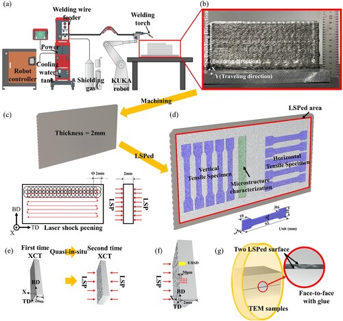
Table 1. Chemical composition of the filler wire (wt. %).
Table 2. Process parameters.
In this study, LSP was applied on both side of the wire arc DED components after the deposition process. For this purpose, an Nd: YAG pulse laser (Beamtech, Beijing China) was employed in this work. Combined with our previous work [Citation27], LSP treatment strategies were selected and are shown in c: 2 mm laser spot diameter, 50% overlap rate, zigzag scan path and double-side treatment. A 1 mm thickness water film served as the containment layer for all LSP processes, with an electric tape acting as the absorbing layer. This study specifically examines the impact of varying pulse energies on mechanical properties. Four different pulse energies were employed in this work (0J (AD), 0.6J, 2.0J, 3.4J).
2.2. Properties and defects characterisation
The uniaxial tensile testing was conducted according to the international standards manual E8M-09, at a constant crosshead displacement speed of 0.6 mm/min. Tensile specimens were cut using electrical discharge machining (EDM) according to the dimensions shown in d.
As shown in e, in order to investigate the evolution of defects in thin-wall structure components before and after LSP treatment, quasi-in-situ CT experiments were carried out. Before the LSP treatment, the unshocked specimens underwent an initial CT scan. Subsequently, after the application of double-sided LSP, a second CT scan was performed using identical scanning parameters. The CT resolution in this study enabled the detection of defects with a diameter exceeding 10 µm.
As shown in f, to obtain the distribution of hardness and residual stress along the depth direction (perpendicular to the LSP surface), sections of the specimens were examined. Microhardness testing was conducted at intervals of 50 µm along the cross-section in the depth direction using the SCTMC 402SXV digital microhardness instrument. Each test was performed set under a 100 g load and 15 s dwell time.
2.3. Microstructural characterisation
The metallographic samples were etched using Keller's reagent after polishing. Fractography and microstructure analysis were conducted using scanning electron microscopy (SEM, SU8230) equipped with an electron backscattered diffraction system (EBSD, Oxford Instruments). EBSD was employed for characterising the orientation of samples. The EBSD samples were prepared using an ion-milling device (Leica-RES102) set at 5 kV, 6°, and processed for 3 h to eliminate residual stresses from the sample surfaces. Transmission electron microscopy (TEM, Talos F200X) was employed to investigate the grain refinement mechanism induced by LSP. g illustrates the preparation of TEM samples, which involved bonding two pieces from the LSP specimen face-to-face with Ab glue and then cutting them into 1.0 mm thick foils. The foils were prepared by ion-milling using Ar+ after mechanical grinding [Citation28].
3. Results
3.1. Defects evolution
3.1.1. Result of quasi-in-situ CT
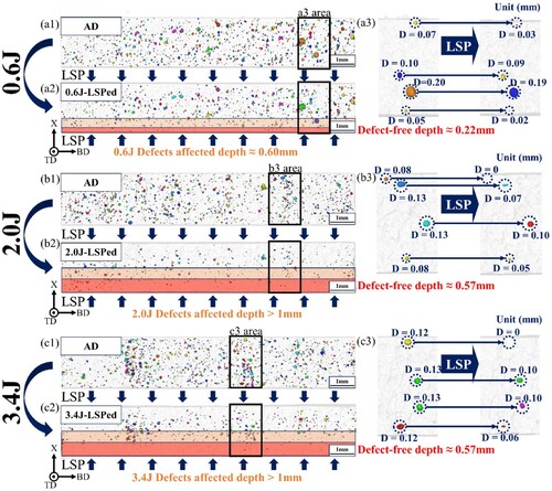
In order to better illustrate the impact of LSP on defects, we performed a CT scan on the same sample before and after LSP treatment. The results are shown in . As depicted in a, the depth of defects affected by LSP treatment with a pulse energy of 0.6J reaches up to 0.6 mm. This implies that defects within this depth range experience a significant reduction or closure, forming a defect-free zone with approximately 0.22 mm from the near-surface. In (a3), several pores at different depths are selected to clearly demonstrate the influence pattern of a 0.6J pulse energy on pores. It is evident that pores near the surface are significantly suppressed, while those in the central region experience minimal impact. In the case of the 2.0 and 3.4 J samples (see (b, c)), the depth of defects-affected exceeds 1 mm, and the defect-free zone near the surface expands to 0.57 mm. Visible in (b3, c3), pores near the surface close after LSP treatment, and those in the central region are also subject to the suppressive effect of LSP treatment.
Figure 2. Quasi-in-situ CT results: (a) 0.6J; (b) 2.0J; (c) 3.4J.
and present the pore diameter distribution, pore volume at different depth regions, and the corresponding changes in pore statistics before and after LSP treatment for the three samples shown in . The inhibitory effect of 0.6J on pores is the least pronounced, with the porosity decreasing from 0.074% before LSP treatment to 0.048% after LSP treatment, reflecting a 36% reduction. Moreover, the pore diameter distribution after LSP treatment remained similar to that before treatment, with only a slight decrease in average diameter (approximately 2 mm). Most pores in the defect-free zone either closed or nearly closed, resulting in an effective diameter close to 0 mm (both from and the variation in pore volume at different depth regions can be observed). Therefore, the pores included in the statistics are mostly located in the central region, where most of the pores are only affected by LSP treatment (still persist) and it is therefore possible to track their reduction in pore diameter, as confirmed by . Consequently, the overall pore distribution remains similar to the original pattern, with only a slight decrease in mean diameter.
Figure 3. Pore data statistics: (a) 0.6J; (b) 2.0J; (c) 3.4J.
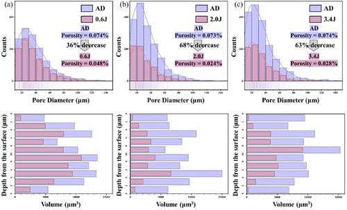
Table 3. Porosity statistics before and after LSP treatment with different pulse energies.
3.1.2. Fractography analysis
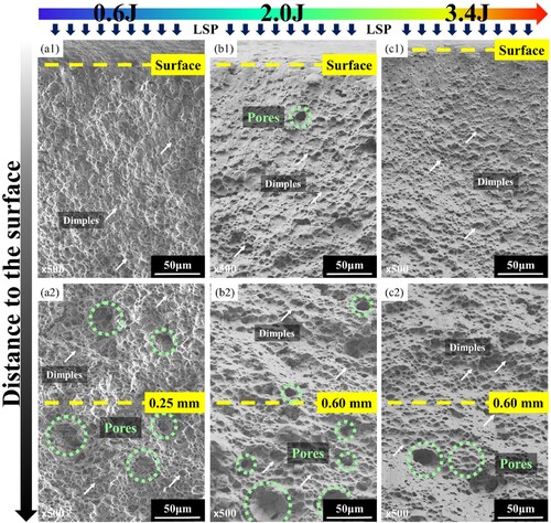
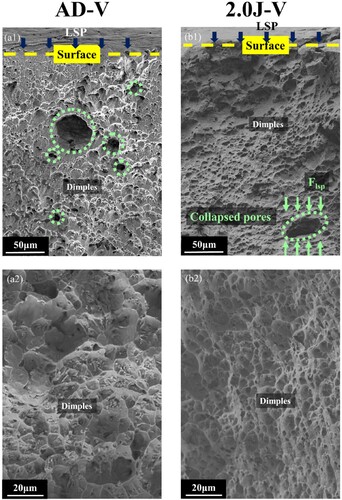
As illustrated in , the inhibitory effect of LSP on defects is prominently manifested on the fracture surfaces. All samples exhibit ductile fracture, with numerous dimples observed on the fracture surfaces. a depicts the fracture surface of the vertical tensile specimen of 0.6J. Near the surface, as shown in (a1), no discernible pores are observed; however, at a depth of approximately 0.25 mm from the treated surface, as indicated in (a1), the presence of defects, mostly pores, becomes apparent. Similarly, as shown in (b1, c1), near the treated surface of the vertical tensile specimens of 2.0J and 3.4J, there are no significant pores observed. However, at a depth of around 0.6 mm, as depicted in (b2, c2), the presence of pore defects becomes abundantly evident. The observed trends in pore distribution due to different pulse energies align with the results obtained in .
Figure 4. Fracture morphology at different distances from the treated surface: (a1) 0.6J-0 mm; (b1) 2.0J-0 mm; (c1) 3.4J-0 mm; (a2) 0.6J-0.25 mm; (b2) 2.0J-0.6 mm; (c2) 3.4J-0.6 mm.
further explores the disparities in the fracture surfaces of vertical tensile specimens subjected with 2.0J compared to their AD counterparts. Upon contrasting (a1) and (b1), it becomes apparent that, after LSP treatment, small pores near the surface have closed, and larger pores have been suppressed. Additionally, as observed in (a2) and (b2), extensive dimples are present on the fracture surfaces.
Figure 5. Fracture morphology of AD sample and 2.0J samples.
Based on the various characterisation results mentioned above, it can be concluded that the pulse energy of 0.6J does not result in a peak enhancement effect, while the indicators for the 2.0J and 3.4J samples tend to be consistent. It can be inferred that the pulse energy of 2.0J and 3.4J has reached a saturation peak.
3.2. Microstructure evolution
illustrates the Electron Backscatter Diffraction (EBSD) results for the cross-sections perpendicular to the impact surface of both the AD and 2.0J samples. In (a, c), the Inverse Pole Figure (IPF) maps are displayed, while (b, d) showcases the corresponding Kernel Average Misorientation (KAM) maps. Geometrically Necessary Dislocations (GNDs) can be calculated using KAM, and it is generally acknowledged that GNDs and KAM are positively correlated [Citation29], both reflecting the extent of local plastic deformation or the magnitude of defect density. In this analysis, four regions along the depth direction of the sample were selected, and the average KAM values for these regions were computed using the following formula [Citation29]:
(1)
(1) where KAML,i represents the local KAM value at point i, and N represents the number of points in the testing region.
Figure 6. EBSD results of AD and 2.0J samples: (a) IPF map of AD sample; (b) KAM map of AD sample; (c) IPF map of 2.0J sample; (d) KAM map of 2.0J sample.
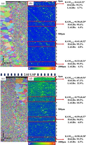
In (b), it is evident that the KAM values exhibit no significant variation with depth, consistently remaining at a relatively low level, with the proportion of high-angle grain boundaries (HAGBs) exceeding 95%. Contrasting this with the sample subjected to 2.0J pulse energy ((b)), a decreasing trend in KAM values is observed as depth increases depths. Within the depth range of 0 - 1000 mm, four equidistant regions were selected along the depth direction for the calculating of KAMavg, HAGBs, and low-angle grain boundaries (LAGBs). With increasing depth, KAMavg gradually decreases from 1.08 ± 0.54° to 0.58 ± 0.38°, HAGB increases from 67.1% to 93.5%, and concurrently LAGB decreases from 32.9% to 6.5%. Particularly near the surface, the 2.0J sample exhibits a significant increase in KAM values and LAGBs values compared to the AD sample.
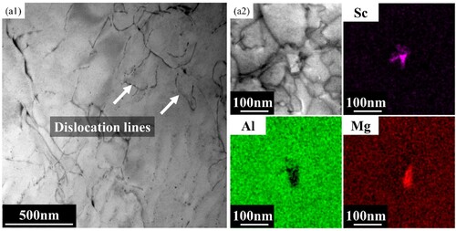
To further investigate the mechanisms behind the enhancement of mechanical properties caused by the 2.0J LSP treatment, a more detailed sub-microstructural analysis was conducted. presents TEM images of the AD sample. Since there was minimal variation in the depth direction of the AD sample, TEM samples were collected from near the surface. In (a1), a sparse distribution of dislocation lines is observed on the surface of the AD sample. At a higher magnification, as shown in (a2), sparse regions rich in Sc and Mg can be identified. Based on previous studies, it is presumed that the Sc-rich phase corresponds to Al3(Sc, Ti) [Citation3], while the Mg-rich phase corresponds to Al2Mg3 [Citation30]. Previous research primarily examined conventionally aged states of sheet materials [Citation31,Citation32], leading to a significant difference in dislocation density in the initial states (AD state in this study, and Aging state in previous research). The rapid solidification and sharp thermal cycle during the wire arc DED process result in the creation of a high dislocation density, a phenomenon confirmed by experimental results in previous studies [Citation33].
Figure 7. TEM results of the AD sample: (a1) low magnification image; (a2) high magnification image and the corresponding EDS maps.
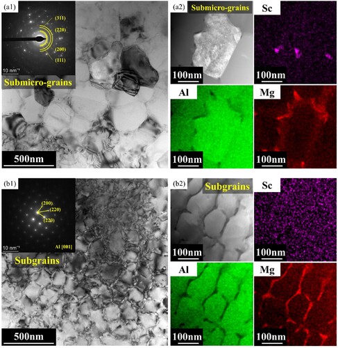
presents TEM images of the 2.0J sample near the surface, at a depth of approximately 50 µm, revealing the existence of two microstructure types: submicro-grains (a) and subgrains (b). In (a1), the submicro-grain region is depicted alongside its selected area electron diffraction (SAED). The submicro-grains measure approximately 300 nm in diameter, and their diffraction patterns create a ring pattern, indicating random grain orientations and the formation of submicro-grains. Furthermore, (a2) demonstrates an EDS mapping of the submicro-grains, revealing a continuous enrichment of Mg along the grain boundaries. b presents the TEM images of the subgrain region. Through SAED analysis of this region, it is observed that the subgrains do not exhibit a significant orientation difference. The EDS-mapping of the subgrains, as depicted in (b2), reveals continuous enrichment of magnesium along the subgrain boundaries.
Figure 8. TEM results of the 2.0J sample taken at a distance of 50 µm from the treated surface: (a1) Low magnification image of submicro-grains; (a2) High magnification image of submicro-grains and the corresponding EDS maps; (b1) Low magnification image of subgrains; (b2) High magnification image of subgrains and the corresponding EDS maps.
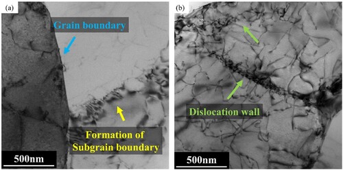
As the depth further increases to approximately 100 µm from the surface, as depicted in , the formation of subgrain boundaries [Citation28] (a) and dislocation walls (DWs) with the potential to transform into subgrain boundaries (b) can be observed in this region. In this depth range, the dislocation density within the matrix is relatively low, and the mobile dislocations tend to aggregate in the two forms with lower energy illustrated in the figure. No submicro-grains are observed within this region.
Figure 9. TEM results of the 2.0J sample taken at a distance of 100 µm from the treated surface: (a)image of formation of subgrain boundary; (b)image of dislocation wall.
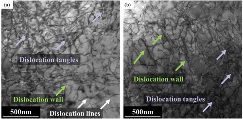
presents TEM images of the 2.0J sample at a depth of approximately 200 µm from the surface. It can be observed that in this region, dislocations have not yet been reorganised into low energy forms. In fact, they are more uniformly distributed compared to 50 and 100 µm depths. Within this area, one can identify dislocation tangles (DTs), DWs, and an extremely limited number of isolated dislocation lines (DLs). Therefore, a higher dislocation density can be found within the matrix, while there is neither submicro-grains nor subgrain boundaries.
Figure 10. TEM results of the 2.0J sample taken at a distance of 200 µm from the treated surface.
3.3. Distribution of microhardness and residual stress
a and b respectively illustrate the microhardness and residual stress distributions along the depth direction to determine the depth of influence of LSP. Regarding the microhardness data, the hardness distribution along the depth direction remains nearly constant for the AD sample, at approximately 102.4 ± 4.3 HV. For the 0.6J sample, the surface hardness reaches 120.4 ± 3.8 HV, but rapidly decreases with increasing depth. At a depth of approximately 0.25 mm from the LSPed surface, it decreases to the level of the AD sample. The 2.0J and 3.4J samples exhibit similar hardness levels and decreasing trends. Near the surface, the hardness can reach 133.6 ± 9.8 HV, and gradually decreases along the depth direction. Within a range of 1 mm from the surface, there is always an increase in hardness. Based on these experimental results, the hardness-affected layer depth of hardness is approximately 0.25 mm at a pulse energy of 0.6J, and increasing the pulse energy to 3.4J both increase the maximal hardness at the surface and affecting depth.
Figure 11. (a) Microhardness and residual stress distribution along the depth direction; (a) microhardness;(b) residual stress.
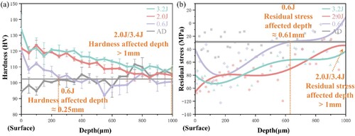
As illustrated in b, the residual stress distribution trends resemble those of microhardness, both decreasing with increasing depth. For the AD sample, the residual stress remains relatively constant along the depth direction, at approximately −28.6 MPa. Upon fitting, the residual stress-affected layer depth for the 0.6J sample is estimated to be approximately 0.61 mm, with a maximum CRS of approximately −80 MPa. The distribution trends of residual stress for the 2.0J and 3.4J samples are also similar, with both samples exhibiting residual stress-affected layer depths greater than 1 mm and maximum CRS reaching around −100 MPa. Zhang et al. [Citation34–36] systematically investigated the gradient variation mechanism of the hardened layer and residual stress field. They elucidated that the increase in hardness stems from surface grain refinement and dislocation accumulation. Moreover, they attributed the decrease in the peak value of the surface CRS to the radial rarefaction wave induced by the plasma shock wave, which generates reverse strain on the sample surface, thereby impeding the maximum CRS at the surface.
3.4. Mechanical properties
(a, b) illustrates the tensile properties of samples treated with different pulse energy. There is no significant anisotropy observed in any of the energy groups. For the AD samples, the mechanical properties achieved a yield strength of 212.2 ± 2.0 MPa, a tensile strength of 383.2 ± 8.9 MPa, and an elongation of 12.4 ± 0.6%. In the 0.6J group, the yield strength exhibited an increase of approximately 16.5% compared to the AD samples, reaching 247.6 ± 4.6 MPa. The tensile strength reached 419.4 ± 12.0 MPa, and the elongation was measured at 15.2 ± 1.1%. For the 2.0J and 3.4J samples, their performance in terms of yield strength, tensile strength, and elongation was remarkably consistent. Relative to the AD samples, the yield strength experienced an increase of approximately 39.5%, reaching 295.8 ± 6.4 MPa, while the tensile strength reached around 429.4 ± 4.5 MPa. The loss in elongation was minimal, measuring at 9.9 ± 0.3%. The trend in changes to yield strength, tensile strength, and elongation with increasing energy can be observed in c. It is evident that at a pulse energy of 0.6J, there is an improvement in mechanical performance, However, this improvement has not yet reached saturation. By the time the pulse energy reaches 2.0J, the enhancement in mechanical properties has saturated. Beyond this point, further increases in pulse energy do not significantly alter the mechanical performance. Therefore, this study focuses on the enhancement mechanisms of wire arc DEDed Al-6Mg-0.3Sc components under LSP treatment at a pulse energy of 2.0J.
Figure 12. Mechanical properties: (a) Stress-strain curves; (b) Statistics of YS, UTS and EL; (c) The changing trend of YS, UTS, and EL; (d) Performance comparison.
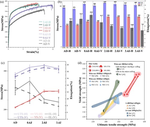
Additionally, d compares the yield strength and tensile strength of the samples treated with a pulse energy of 2.0 J. In this study similar components were manufactured using other forming processes as reported in previous research. The performance of the AD samples in this study has already surpassed that of most conventionally processed components of the same material type. This opens up new possibilities for additive manufacturing of large-sized thin-walled components.
As cast:[Citation37,Citation38]; L-DEDed: [Citation39];Wire arc DEDed ALMGSCZR:[Citation40,Citation41]; Wire arc DEDed almgsc:[Citation11,Citation12,Citation40,Citation42];INTERLAYERROOLING,[Citation5,Citation43]
4. Discussion
4.1. Mechanism of submicro-grains formation
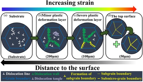
Aluminum alloy, characterised by a face-centered cubic (FCC) crystal structure, demonstrates a high stacking fault energy (SFE) ranging from approximately 135 to 220 mJ/m2, as reported in previous studies [Citation44]. Plastic deformation and grain refinement of aluminum alloys with high SFE are primarily governed by the motion of dislocations [Citation31]. Based on the earlier characterisation results, the effect of LSP decreases gradually along the depth direction. Simultaneously, plastic deformation along the depth direction also decreases [Citation24,Citation31]. Therefore, the formation of submicro-grains was only found in regions undergoing severe plastic deformation, i.e. the topmost surface. illustrates the schematic formation of submicro-grains and simultaneously depicts the microstructural evolution corresponding to various levels of plastic deformation at varying depths.
Stage Ⅰ: a and reveal the microstructure of the near-surface region before the LSP treatment and the corresponding microstructure outside the affected zone of LSP. The wire arc DED process generates numerous DLs, due to the rapid cooling of the molten pool, resulting in abundant dislocations. Additionally, the cyclic thermal effects additive manufacturing process involves facilitate dislocation movement and DLs formation [Citation45].
Stage Ⅱ: During the LSP process, the plastic strain near the surface gradually increases, leading to a thin layer of a minor plastic deformation layer after LSP treatment. b and . illustrate the microstructure at this stage. The accumulation of plastic deformation, results in the significant generation of dislocations, promoting the formation of DTs and DWs within the grains.
Stage Ⅲ: As shown in c and , with an increasing degree of plastic deformation (similar to the deformation level around 100 µm), defects such as dislocations and interfaces continue to accumulate [Citation46]. This accumulation drives the material into a thermodynamically unstable state. To minimise the system’s energy, dislocation annihilation and rearrangement occur within the grains, reducing the number of discrete dislocations and formation of subgrain boundaries.
Stage Ⅳ: As plastic strain reaches its peak, specifically in the stage of near-surface plastic strain state, as illustrated in d and , the high strain rates associated with LSP treatment challenge conventional recrystallization theories. Since LSP is conducted at room temperature, traditional recrystallization theory fails to explain the grain refinement behaviour. The phenomenon of cDRX [Citation47] indicates that new grains form due to the accumulation of dislocations from deformation, leading to an increase in the misorientation of subgrain boundaries. This process gradually transforms some subgrain boundaries into submicro-grains with HAGBs under conditions of high strain.
Figure 13. Schematic diagram illustrating the mechanism of grain refinement as plastic deformation increases: (a) stage Ⅰ; (b) stage Ⅱ; (c) stage Ⅲ; (d) stage Ⅳ.
4.2. Mechanism of Mg aggregation at the subgrain boundaries
As depicted in (b2), LSP treatment results in the enrichment of Mg at the subgrain boundaries. We endeavour to elucidate the process by which the LSP treatment induces Mg enrichment at the subgrain boundaries. Elemental segregation at grain boundaries induced by severe plastic deformation has been reported in several studies [Citation48,Citation49]. LSP represents a typical high strain rate processing technique, and severe plastic deformation occurs during LSP treatment. It has been observed that the accumulation of vacancies at subgrain boundaries, induced by a large number of dislocations and vacancies deformation, drags Mg atoms toward the boundaries [Citation50]. Additionally, the abundance of dislocations provides pathways for Mg atom migration [Citation51], resulting in the enrichment of Mg at the subgrain boundaries after LSP treatment.
4.3. Mechanism of mechanical properties enhancement
Following the LSP treatment with a pulse energy of 2.0 J, the yield strength increased from 212.2 ± 2.0 MPa to 295.8 ± 6.4 MPa, while the elongation was maintained at 9.9 ± 0.3%, achieving a concurrent growth in strength-ductility synergy. However, the gradient microstructure introduced by LSP along the depth direction complicates the precise calculation of the strength-ductility synergy mechanism. The introduction of submicro-scale equiaxed grains by LSP transforms the original heterogeneous microstructure of microscale equiaxed grains/columnar grains in the AD sample into a more complex microstructure consisting of submicro-scale equiaxed grains/microscale equiaxed grains/columnar grains.
Yield strength enhancement mechanism: Undoubtedly, the introduction of submicro-grains brings about grain boundary strengthening, enhancing the yield strength. According to the Hall-Petch equation, a significant improvement is expected as the grain size transitions from the microscale to the submicro-scale [Citation52]:
(2)
(2) where σ0 is the threshold stress in pure aluminum [Citation53], k is a constant representing the relative strengthening contribution from grain boundaries, and d is the average grain size of the alloy. Another significant factor contributing to the substantial increase in yield strength is dislocation strengthening, which can be described by the following equation [Citation54]:
(3)
(3) where α = 0.24 is a constant, M = 3.06 is the Taylor factor, G = 26 GPa is the shear modulus, b = 0.286 nm is the Burgers vector, and ρ is the dislocation forest density. Therefore, LSP treatment results in a significant increase in dislocation density, leading to a substantial enhancement of the mechanical properties of the component. Moreover, previous studies [Citation47,Citation55] have indicated that the non-equilibrium state induced by strain in the strain-induced boundaries (boundaries between submicro-grains and the substrate) leads to significant distortion within submicro-grains/subgrains, generating internal stresses. These high internal stresses can function as back stresses for the motion of dislocations, and thus may contribute to the strengthening mechanism.
Strength-ductility synergy mechanism: The complex heterogenous microstructure of submicro-scale equiaxed grains/microscale equiaxed grains/columnar grains in the 2.0J sample promotes strength-ductility synergy. Research by Zhou et al. [Citation56] suggests that this type of microstructure is more favourable for capturing GNDs, accommodating a higher dislocation density, thereby demonstrating superior strength and plastic deformation capability.
In the case of wire arc DEDed Al-6Mg-0.3Sc components subjected to 2.0J LSP treatment, during the tensile process, the complex heterogeneous microstructure exhibits distinct behaviours: soft domains undergo plastic deformation initially, while hard domains remain elastic. Consequently, strain is non-uniformly distributed, with regions characterised by larger grain sizes experiencing significantly more plastic strain than those with smaller grain sizes [Citation57]. Due to the discoordination of deformation within the complex heterogeneous microstructure, hetero-deformation induced (HDI) strengthening and HDI strain hardening occur, contributing to enhancements in yield strength and ductility, respectively [Citation58]. Throughout the tensile deformation process, the distribution of GNDs is also non-uniform, with regions of smaller grain sizes accumulating more GNDs. On a macroscopic scale, compared to a homogeneous microstructure, the complex heterogeneous microstructure can accumulate a greater number of GNDs, achieving a perfect combination of high strength and large ductility.
Limitation in mechanical property enhancement with increasing energy: As observed in the 3.4J samples in this study, this phenomenon, where mechanical properties cannot infinitely increase with rising pulse energy, has also been reported in other alloy studies [Citation59,Citation60]. According to typical Peyre's elastic-plastic model, the plastic deformation will tend to be saturated at a peak pressure around 2–2.5 Hugoniot elastic limit (HEL) [Citation61]. With the increase in energy, as previously discussed, there is a significant introduction of dislocations and grain refinement, leading to the enhancement of mechanical properties [Citation62]. However, due to the material's plastic deformation limit, additional laser energy cannot infinitely increase the thickness of the hardened layer in LSP processing [Citation63]. On the contrary, more pronounced work hardening and a more complex accumulation of dislocation tangles make dislocation movement difficult, resulting in premature failure.
5. Conclusion
In this study, high-performance Al-6Mg-0.3Sc components were fabricated using wire arc DED without heat treatment, and their performance was further enhanced through LSP treatment. A comparative analysis of the effects of pulse energies (0.6J, 2.0J, and 3.4J) on defects and mechanical properties was conducted. The summarised conclusions are as follows:
LSP with a pulse energy of 2.0J induces CRS and enhances microhardness, with an effective depth > 1 mm, while significantly reduce defects by approximately 68% and forms a defect-free zone within 0.57 mm near the surface.
LSP treatment with a pulse energy of 2.0J enhances the mechanical properties of wire arc DED Al-6Mg-0.3Sc components, resulting in a yield strength of 295.8 ± 6.4 MPa, tensile strength of 429.4 ± 4.5 MPa, and elongation of 9.9 ± 0.3%. Compared to the AD sample, the yield strength increased by 39.5%, the tensile strength increased by 12.1%, while the elongation decreased by only 2.5%.
LSP with a pulse energy of 2.0J induces gradient microstructures along the depth direction, resulting in the formation of submicro-grains and subgrains near the surface. The trimodal structure, consisting of submicro-scale equiaxed grains, microscale equiaxed grains, and columnar grains, observed in LSP-treated wire arc DEDed Al-Mg-Sc components, contributes to the synergistic enhancement of strength and ductility.
Acknowledgements
The authors acknowledge the finical support from the National Natural Science Foundation of China [Grant numbers 52205414, 52275374], as well as the fund of Young Elite Scientists Sponsorship Program by CAST [Grant number 2021QNRC001]. Special thanks are extended to Hang Guo and Yanan Chen from Instrumental Analysis Center of Xi’an Jiaotong University.
Disclosure statement
No potential conflict of interest was reported by the author(s).
Data availability statement
Data will be made available on request.
Additional information
Funding
References
- Li Y, Su C, Zhu J. Comprehensive review of wire arc additive manufacturing: hardware system, physical process, monitoring, property characterization, application and future prospects. Results Eng. 2022;13:100330. doi:10.1016/j.rineng.2021.100330
- Cong B, Ding J, Williams S. Effect of arc mode in cold metal transfer process on porosity of additively manufactured Al-6.3% Cu alloy. Int J Adv Manuf Technol. 2015;76:1593–1606. doi:10.1007/s00170-014-6346-x
- Zhou Y, Chang T, Fang X, et al. Tailoring the mechanical properties and thermal stability of additive manufactured micro-alloyed Al-Cu alloy via multi-stage heat treatment. Mater Des. 2023;233:112287. doi:10.1016/j.matdes.2023.112287
- Guo Y, Han Q, Lu W, et al. Microstructure tuning enables synergistic improvements in strength and ductility of wire-arc additive manufactured commercial Al-Zn-Mg-Cu alloys. Virtual Phys Prototyp. 2022;17:649–661. doi:10.1080/17452759.2022.2048236
- Gu J, Yang S, Gao M, et al. Micropore evolution in additively manufactured aluminum alloys under heat treatment and inter-layer rolling. Mater Design. 2020;186:108288. doi:10.1016/j.matdes.2019.108288
- Fang X, Zhang L, Chen G, et al. Microstructure evolution of wire-arc additively manufactured 2319 aluminum alloy with interlayer hammering. Mater Sci Eng: A. 2021;800:140168. doi:10.1016/j.msea.2020.140168
- Dong W, Jimenez XA, To AC. Temperature-dependent modified inherent strain method for predicting residual stress and distortion of Ti6Al4V walls manufactured by wire-arc directed energy deposition. Addit Manuf. 2023;62:103386. doi:10.1016/j.addma.2022.103386
- Gu J, Ding J, Williams SW, et al. The effect of inter-layer cold working and post-deposition heat treatment on porosity in additively manufactured aluminum alloys. J Mater Process Technol. 2016;230:26–34. doi:10.1016/j.jmatprotec.2015.11.006
- Panchenko O, Kurushkin D, Mushnikov I, et al. A high-performance WAAM process for Al–Mg–Mn using controlled short-circuiting metal transfer at increased wire feed rate and increased travel speed. Mater Design. 2020;195:109040. doi:10.1016/j.matdes.2020.109040
- Ren L, Gu H, Wang W, et al. The microstructure and properties of an Al-Mg-0.3Sc alloy deposited by wire Arc additive manufacturing. Metals. 2020;10:320. doi:10.3390/met10030320
- Ma S, Jiang M, Chen X, et al. Macro/micro-structure and mechanical properties of Al-6Mg-0.3Sc alloy fabricated by oscillating laser-arc hybrid additive manufacturing. J Alloys Compd. 2022;929:167325. doi:10.1016/j.jallcom.2022.167325
- Xia Y, Cai X, Dong B, et al. Wire arc additive manufacturing of Al-Mg-Sc alloy: An analysis of the effect of Sc on microstructure and mechanical properties. Mater Charact. 2023;203:113116. doi:10.1016/j.matchar.2023.113116
- Li R, Wang M, Li Z, et al. Developing a high-strength Al-Mg-Si-Sc-Zr alloy for selective laser melting: crack-inhibiting and multiple strengthening mechanisms. Acta Mater. 2020;193:83–98. doi:10.1016/j.actamat.2020.03.060
- Kendig KL, Miracle DB. Strengthening mechanisms of an Al-Mg-Sc-Zr alloy. Acta Mater. 2002;50:4165–4175. doi:10.1016/S1359-6454(02)00258-6
- Geng H, Li J, Xiong J, et al. Geometric limitation and tensile properties of wire and arc additive manufacturing 5A06 aluminum alloy parts. J Mater Eng Perform. 2017;26:621–629. doi:10.1007/s11665-016-2480-y
- Ma PP, Liu CH, Wu CL, et al. Mechanical properties enhanced by deformation-modified precipitation of θ′-phase approximants in an Al-Cu alloy. Mater Sci Eng: A. 2016;676:138–145. doi:10.1016/j.msea.2016.08.068
- Deng W, Wang C, Lu H, et al. Progressive developments, challenges and future trends in laser shock peening of metallic materials and alloys: A comprehensive review. Int J Mach Tools Manuf. 2023;191:104061. doi:10.1016/j.ijmachtools.2023.104061
- Ren XD, Zhang YK, Yongzhuo HF, et al. Effect of laser shock processing on the fatigue crack initiation and propagation of 7050-T7451 aluminum alloy. Mater Sci Eng: A. 2011;528:2899–2903. doi:10.1016/j.msea.2010.12.058
- Lu J, Lu H, Xu X, et al. High-performance integrated additive manufacturing with laser shock peening –induced microstructural evolution and improvement in mechanical properties of Ti6Al4V alloy components. Int J Mach Tools Manuf. 2020;148:103475. doi:10.1016/j.ijmachtools.2019.103475
- Lu H, Wu L, Wei H, et al. Microstructural evolution and tensile property enhancement of remanufactured Ti6Al4 V using hybrid manufacturing of laser directed energy deposition with laser shock peening. Addit Manuf. 2022;55:102877. doi:10.1016/j.addma.2022.102877
- Lu H, Deng W, Luo K, et al. Tailoring microstructure of additively manufactured Ti6Al4V titanium alloy using hybrid additive manufacturing technology. Addit Manuf. 2023;63:103416. doi:10.1016/j.addma.2023.103416
- Lv J, Luo K, Lu H, et al. Achieving high strength and ductility in selective laser melting Ti-6Al-4V alloy by laser shock peening. J Alloys Compd. 2022;899:163335. doi:10.1016/j.jallcom.2021.163335
- Sun R, Li L, Zhu Y, et al. Microstructure, residual stress and tensile properties control of wire-arc additive manufactured 2319 aluminum alloy with laser shock peening. J Alloys Compd. 2018;747:255–265. doi:10.1016/j.jallcom.2018.02.353
- Li X, Fang X, Zhang M, et al. Gradient microstructure and prominent performance of wire-arc directed energy deposited magnesium alloy via laser shock peening. Int J Mach Tools Manuf. 2023;188:104029. doi:10.1016/j.ijmachtools.2023.104029
- Jing Y, Fang X, Geng Y, et al. Simultaneous strength and ductility enhancement of wire-arc directed energy deposited Al–Cu alloy by interlayer laser shock peening. Mater Sci Eng: A. 2023;887:145699. doi:10.1016/j.msea.2023.145699
- Chang T, Fang X, Liu G, et al. Wire and arc additive manufacturing of dissimilar 2319 and 5B06 aluminum alloys. J Mater Sci Technol. 2022;124:65–75. doi:10.1016/j.jmst.2022.02.024
- Chang T, Zhang H, Fang X, et al. Tailoring precipitation of directed energy deposited Al-Cu alloy via laser shock peening. Addit. Manuf. 2023;73:103652. doi:10.1016/j.addma.2023.103652
- Trdan U, Skarba M, Grum J. Laser shock peening effect on the dislocation transitions and grain refinement of Al–Mg–Si alloy. Mater. Charact. 2014;97:57–68. doi:10.1016/j.matchar.2014.08.020
- Zhi H, Zhang C, Antonov S, et al. Investigations of dislocation-type evolution and strain hardening during mechanical twinning in Fe-22Mn-0.6C twinning-induced plasticity steel. Acta Mater. 2020;195:371–382. doi:10.1016/j.actamat.2020.05.062
- Goswami R, Spanos G, Pao PS, et al. Precipitation behavior of the ß phase in Al-5083. Mater Sci Eng: A. 2010;527:1089–1095. doi:10.1016/j.msea.2009.10.007
- Lu JZ, Luo KY, Zhang YK, et al. Grain refinement of LY2 aluminum alloy induced by ultra-high plastic strain during multiple laser shock processing impacts. Acta Mater. 2010;58:3984–3994. doi:10.1016/j.actamat.2010.03.026
- Yang Y, Lian X, Zhou K, et al. Effects of laser shock peening on microstructures and properties of 2195 Al-Li alloy, J. Alloys Compd. 2019;781:330–336. doi:10.1016/j.jallcom.2018.12.118
- Dong B, Cai X, Lin S, et al. Wire arc additive manufacturing of Al-Zn-Mg-Cu alloy: microstructures and mechanical properties. Addit Manuf. 2020;36:101447. doi:10.1016/j.addma.2020.101447
- Dai W, Guo W, Xiao J, et al. Tailoring properties of directed energy deposited Al-Mg alloy by balancing laser shock peening and heat treatment. J Mater Sci Technol. 2024;203:78–96. doi:10.1016/j.jmst.2024.03.051
- Chi J, Cai Z, Zhang H, et al. Combining manufacturing of titanium alloy through direct energy deposition and laser shock peening processes. Mater Design. 2021;203:109626. doi:10.1016/j.matdes.2021.109626
- Zhang Y, Guo W, Shi J, et al. Improved rotating bending fatigue performance of laser directed energy deposited Ti6Al4 V alloys by laser shock peening. J Alloys Compd. 2024;980:173664. doi:10.1016/j.jallcom.2024.173664
- Wang Y, Yang B, Gao M, et al. Microstructure evolution, mechanical property response and strengthening mechanism induced by compositional effects in Al–6 Mg alloys. Mater Design. 2022;220:110849. doi:10.1016/j.matdes.2022.110849
- Wang Z, Lin X, Wang J, et al. Remarkable strength-impact toughness conflict in high-strength Al-Mg-Sc-Zr alloy fabricated via laser powder bed fusion additive manufacturing. Addit Manuf. 2022;59:103093. doi:10.1016/j.addma.2022.103093
- Wang Z, Lin X, Kang N, et al. Directed energy deposition additive manufacturing of a Sc/Zr-modified Al-Mg alloy: effect of thermal history on microstructural evolution and mechanical properties. Mater Sci Eng: A. 2021;802:140606. doi:10.1016/j.msea.2020.140606
- Sales A, Ricketts NJ. Effect of scandium on wire Arc additive manufacturing of 5 series aluminium alloys. In: C Chesonis, editor. Light metals 2019. Cham: Springer International Publishing; 2019. p. 1455–1461. doi:10.1007/978-3-030-05864-7_182
- Ponomareva T, Ponomarev M, Kisarev A, et al. Wire arc additive manufacturing of Al-Mg alloy with the addition of scandium and zirconium. Materials. 2021;14:3665. doi:10.3390/ma14133665
- Ma S, Chen X, Jiang M, et al. Surface morphology, microstructure and mechanical properties of Al–Mg–Sc alloy thin wall produced by laser-arc hybrid additive manufacturing. Thin Wall Struct. 2023;186:110674. doi:10.1016/j.tws.2023.110674
- Xie C, Wu S, Yu Y, et al. Defect-correlated fatigue resistance of additively manufactured Al-Mg4.5Mn alloy with in situ micro-rolling. J Mater Process Technol. 2021;291:117039. doi:10.1016/j.jmatprotec.2020.117039
- Muzyk M, Pakiela Z, Kurzydlowski KJ. Ab initio calculations of the generalized stacking fault energy in aluminium alloys. Scr Mater. 2011;64:916–918. doi:10.1016/j.scriptamat.2011.01.034
- Dong B, Cai X, Xia Y, et al. Effects of interlayer temperature on the microstructures of wire arc additive manufactured Al-Zn-Mg-Cu alloy: insights into texture responses and dynamic precipitation behaviors. Addit Manuf. 2021;48:102453. doi:10.1016/j.addma.2021.102453
- Huang K, Marthinsen K, Zhao Q, et al. Logé, The double-edge effect of second-phase particles on the recrystallization behaviour and associated mechanical properties of metallic materials. Prog Mater Sci. 2018;92:284–359. doi:10.1016/j.pmatsci.2017.10.004
- Sakai T, Belyakov A, Kaibyshev R, et al. Dynamic and post-dynamic recrystallization under hot, cold and severe plastic deformation conditions. Prog Mater Sci. 2014;60:130–207. doi:10.1016/j.pmatsci.2013.09.002
- Sauvage X, Duchaussoy A, Zaher G. Strain induced segregations in severely deformed materials. Mater Trans. 2019;60:1151–1158. doi:10.2320/matertrans.MF201919
- Valiev RZ, Enikeev NA, Murashkin MY, et al. On the origin of the extremely high strength of ultrafine-grained Al alloys produced by severe plastic deformation. Scr Mater. 2010;63:949–952. doi:10.1016/j.scriptamat.2010.07.014
- Sauvage X, Enikeev N, Valiev R, et al. Atomic-scale analysis of the segregation and precipitation mechanisms in a severely deformed Al–Mg alloy. Acta Mater. 2014;72:125–136. doi:10.1016/j.actamat.2014.03.033
- Amouyal Y, Divinski SV, Klinger L, et al. Grain boundary diffusion and recrystallization in ultrafine grain copper produced by equal channel angular pressing. Acta Mater. 2008;56:5500–5513. doi:10.1016/j.actamat.2008.07.029
- Xiao X, Guo Y, Zhang R, et al. Achieving uniform plasticity in a high strength Al-Mn-Sc based alloy through laser-directed energy deposition. Addit Manuf. 2022;60:103273. doi:10.1016/j.addma.2022.103273
- Kumar N, Mishra RS. Additivity of strengthening mechanisms in ultrafine grained Al–Mg–Sc alloy. Mater Sci Eng: A. 2013;580:175–183. doi:10.1016/j.msea.2013.05.006
- Kamikawa N, Huang X, Tsuji N, et al. Strengthening mechanisms in nanostructured high-purity aluminium deformed to high strain and annealed. Acta Mater. 2009;57:4198–4208. doi:10.1016/j.actamat.2009.05.017
- Zhu Y, Wu X. Perspective on hetero-deformation induced (HDI) hardening and back stress. Mater Res Lett. 2019;7:393–398. doi:10.1080/21663831.2019.1616331
- Zhou Y, Fang X, Lin X, et al. Tensile deformation behavior of triple heterogeneous microstructure comprising fine equiaxed/coarse equiaxed/columnar grains in AlCu/AlMgSc bimetal fabricated via dual-wire arc direct energy deposition. J Mater Sci Technol. 2024: S100503022400015X. doi:10.1016/j.jmst.2023.11.026
- Li G, Jiang J, Ma H, et al. Superior strength–ductility synergy in three-dimensional heterogeneous-nanostructured metals. Acta Mater. 2023;256:119143. doi:10.1016/j.actamat.2023.119143
- Zhu Y, Wu X. Heterostructured materials. Prog Mater Sci. 2023;131:101019. doi:10.1016/j.pmatsci.2022.101019
- Ren XD, Huang JJ, Zhou WF, et al. Surface nano-crystallization of AZ91D magnesium alloy induced by laser shock processing. Mater Des. 2015;86:421–426. doi:10.1016/j.matdes.2015.07.039
- Zhou W, Ren X, Liu F, et al. Nanocrystallization in the duplex Ti-6Al-4V alloy processed by multiple laser shock peening. Metals. 2016;6:297. doi:10.3390/met6120297
- Jing Y, Fang X, Xi N, et al. Investigation of microstructure and mechanical properties evolution in 7050 aluminum alloy and 316L stainless steel treated by laser shock peening. Mater Charact. 2021;182:111571. doi:10.1016/j.matchar.2021.111571
- Tong Z, Liu H, Jiao J, et al. Improving the strength and ductility of laser directed energy deposited CrMnFeCoNi high-entropy alloy by laser shock peening. Addit Manuf. 2020;35:101417. doi:10.1016/j.addma.2020.101417
- Ren CX, Wang Q, Zhang ZJ, et al. Surface strengthening behaviors of four structural steels processed by surface spinning strengthening. Mater Sci Eng A. 2017;704:262–273. doi:10.1016/j.msea.2017.08.007