
 ?Mathematical formulae have been encoded as MathML and are displayed in this HTML version using MathJax in order to improve their display. Uncheck the box to turn MathJax off. This feature requires Javascript. Click on a formula to zoom.
ABSTRACT
This study demonstrates the successful fabrication of a multi-material 18Ni(300) maraging steel – CoCrMo alloy using laser powder bed fusion (L-PBF), which in its as-built state, displays suboptimal mechanical performance. Addressing this, we propose different heat treatments that mutually enhance the properties of both alloys. Comparative analysis of texture development, precipitation sequence and mechanical properties of the dual structures at different scales has been conducted. The results indicate the cooperative strengthening of intragranular γ–ϵ transformation in CoCrMo, and Ni3Ti precipitation in maraging steel. Adding the solution treatment also balanced the formation of acicular Ni3Ti clusters with (Fe, Ni, Co)2(Ti, Mo) precipitates, and revealed that chemical segregation influences austenite reversion. Initial evidence of local grain variant selection has been revealed in as-built samples due to thermal cycling and austenite reversion, which generates residual stresses, recoil forces and convective flow. Surprisingly, the missing variants can also be inherited after heat treatment with insufficient solution temperatures.
1. Introduction
Multi-material additive manufacturing (MMAM) introduces a new design degree of freedom through the strategic placement of compatible alloys within a heterogenous component. This approach results in multi-functional, cost-effective parts with tunable local characteristics, reduced reliance on vulnerable joint systems and adaptability to combined environmental constraints [Citation1–3]. Laser powder bed fusion (L-PBF) also stands out as an MMAM method due to its near-net shape fabrication capabilities [Citation3,Citation4] that promote raw material efficiency and limit alloy migration through interdiffusion [Citation5,Citation6]. The high in-plane print resolution [Citation3,Citation5] due to the incremental deposition also allows the fabrication of components with unconventional property combinations, which is demonstrated in multi-functional metal metamaterials that are only achieved due to powder compositions that are customised for L-PBF [Citation7,Citation8]. The choice between a sharp, gradual, or intermediate material transition [Citation9] should consider the solidification dynamics and compositional fit of the individual feed materials to be fused.
In this work, the combination of maraging steel and CoCrMo alloy was extensively investigated for MMAM, followed by post-processing. The directionality of the mechanical properties in the final product can be controlled according to the individual merits of both alloys: Maraging steels [Citation10–12], known for having superior strength, weldability and easier serviceability, can be tactically merged with CoCrMo alloys [Citation13,Citation14] which have better thermal stability, higher wear resistance and inherent biocompatibility. Numerous studies have successfully combined these alloys with different materials, such as IN718 [Citation15,Citation16], Ti6Al4 V [Citation17], SS316 [Citation18] and CrMn steel [Citation19]. Our previous work has also demonstrated the successful continuous L-PBF printing of 18Ni(300) maraging steel and CoCrMo alloy [Citation20]. The comparison between the mechanical properties of the base alloys and the combined structure has also been explored. The initial motivation for this material combination is for thermal transport and injection molding applications, wherein local material choice heavily depends on cost and complexity considerations [Citation20]. In the present study, we have investigated multiple strategic heat treatment schedules aimed at expanding the potential applicability of this alloy combination to components that require enhanced mechanical performance and standard certification, such as loadbearing structural components [Citation11], heavy tooling and cutting machinery, impact energy absorption assemblies [Citation21] and automotive engine components [Citation22]. Moreover, maraging steel showed an unusual martensitic transformation pattern at the interface after conventional heat treatment in [Citation20]. Through analysis of texture evolution and precipitate formation close to the interface after different heat treatments, this work demonstrates the influence of melt pool dynamics to martensitic phase transformation and variant selection.
Two main challenges emerge when designing a suitable heat treatment schedule for an MMAM component: first, the desired internal structure, dislocation distribution, texture, mechanical properties and phase transformations should be achieved in each alloy; and second, the resulting alloy migration, intermetallic precipitation and phase distribution along the transition zones should not introduce points of weaknesses and compromise the integrity of the entire structure. Reviews on multi-material fabrication have highlighted the lack of literature regarding the mechanisms that form interfacial microstructures and defects, as well as the techniques to enhance interfacial bonding [Citation5,Citation23,Citation24]. For CoCrMo alloys, the balance between the metastable γ-phase and martensitic ϵ-phase hinges on the interactions between several microstructural elements including stacking faults [Citation25], recrystallised grains, coherent twins, pinning precipitates [Citation26] and interstitial elements [Citation27]. A prolonged exposure to 1150°C for 6 h has been proven successful in reducing residual stresses and eliminating anisotropic behaviour for CoCrMo alloys produced using L-PBF, resulting in a stress-free structure with equiaxed grains [Citation28]. Depending on the accumulation of Shockley partials and density of dislocations, the γ–ϵ transformation can take place through strain addition [Citation13], annealing [Citation25], diffusional massive transformation [Citation29], or rapid cooling [Citation30]. The subsequent growth predominantly occurs along parallel striations that extend in {111}γ habit planes [Citation31].
For martensitic transformation in maraging steels, which will be the focus in this study, the crystal symmetry of the parent austenite (γ) grain often dictates a predetermined set of martensite child (α′) orientations or ‘variants’ that minimises the lattice mismatch during phase change [Citation32]. Several orientation relationships have been used to define texture transfer after steel transformations, the simplest being the Bain relationship described as {001}γ || {001}α and <100>γ || <110>α [Citation33]. This equates to a 45° rotation in each of the three <100> axes. The Kurdjumov-Sachs (KS) relationship represents 24 possible variants through 90° rotations along the 24 <112> axes with the parallelism condition {111}γ || {110}α and <10>γ || <1
1>α. On the other hand, the Nishiyama–Wassermann (NW) relationship corresponds to 12 potential variants through 95.2° rotations about the <−1 + 21/2 + 31/2, 1 + 21/2 + 31/2, 21/2> axes [Citation34] specified by the {111}γ || {110}α and <
11>γ || <1
0>α condition. Surrounding each Bain variant are four NW variants, each in between two of eight total KS variants that are clustered into relevant Bain Circles [Citation35]. Other mutual orientation relations have been comprehensively investigated in Refs. [Citation36,Citation37].
The direct analysis of transformation texture development in AM structures becomes challenging due to the columnar dendritic morphology and accumulated thermal cycling during printing, which blurs the original γ grain boundaries. However, the parent γ-phase retention occurring in the interface of the MMAM component in this study reveals a new avenue for phase transformation analysis. Variant distribution and local selection in additively manufactured maraging steels have been recently observed by Truong et al. [Citation38], but the analysis relied on full parent reconstruction due to the single-phase matrix after solidification. Since retained γ-phase exists in the interface of the multi-material component in this study, the orientation of the parent and child grains can be directly correlated. Recognising the other processing considerations explained above, the primary objective of this study is to systematically investigate the effects of continuous LPBF and heat treatments on the mechanical properties and microstructural evolution in CoCrMo alloy-maraging steel dual structure. Main concepts of phase transformation, texture development, strain distribution and precipitate nucleation were correlated to the resulting hardness and tensile properties. This work also proposes new perspectives on solidification and variant selection during AM and provides guidance in post-processing analysis for MMAM components.
2. Materials and methods
2.1. Alloy preparation
The fabricated MMAM component was produced from voestalpine Additive Manufacturing Center Ltd. (vAMC) in Mississauga, Ontario, Canada, using gas atomised powders of maraging steels and CoCrMo alloys with particle diameter ranges of 15–70 μm and 15–50 μm, respectively. The continuous L-PBF process has been discussed in detail on the previous work presented in Ref. [Citation20], utilising an EOS M290 machine under Ar gas atmosphere equipped with the following set parameters for both powders: 1100 mm/s laser speed, zigzag stripe hatching style with 50° alternating rotation, 50 µm target layer thickness, hatch distance of 0.1 mm and laser power of 280–300 W. The maraging steel layers are loaded and melted first, syncing the switch in the powder recoater to CoCrMo alloy powders once the target volume is reached. No cracks were observed in the component after printing. The chemical composition of the powders was validated through Inductively Coupled Plasma – Optical Emission Spectroscopy (ICP–OES) tests, and the elemental constituents are shown in . Representative samples and tensile coupons incorporating the material transition zone in the middle were prepared for separate analysis and heat treatment.
Table 1. Chemical composition of maraging steel and CoCrMo feed powders (in wt.%).
2.2. Heat treatment
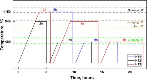
As-built samples were subjected to three heat treatment conditions detailed in using a quartz tube furnace in an Ar gas atmosphere. Differential scanning calorimetry investigations on CoCrMo fabricated using L-PBF [Citation39] identified two distinct endothermic peaks at 965°C and 1139°C, which are associated with the γ–ϵ phase transition and precipitate dissolution temperatures, respectively. On the other hand, dilatometry tests on maraging steel samples in this study using a 1°C/s heating rate determined the precipitation range of 450–580°C, the austenite start (As) at 660°C and the austenite finish (Af) at 820°C, while the solutionising temperature is expected above 1100°C [Citation40]. The temperature and exposure durations were strategically chosen based on the desired mechanical properties and internal structures for both alloys. For HT1, exposure at 1150°C for 6 h followed by 490°C for 6 h were employed. The first step is to trigger complete solution treatment, stress relief and high ductility recovery in the CoCrMo at the expense of coarser prior austenite grain size in maraging steel, while the second step is for aging treatment of maraging steel below the γ–ϵ transformation region of CoCrMo. For HT2, soaking at 940°C for 2 h followed by 490°C for 6 h were chosen. This focuses on achieving high strength in maraging steel at the expense of some ductility in CoCrMo. The first step acts as an austenitising treatment for maraging steel and short aging for CoCrMo alloy, while the second step acts as an aging treatment for maraging steel similar to HT1. The final treatment condition in HT3 is performed in three steps: 1150°C for 2 h + 940°C for 5 h + 490°C for 6 h. With the aim of balancing the strength achieved from both alloys, the first step is a shortened solution treatment to recover some ductility in CoCrMo, followed by considerable γ–ϵ phase massive transformation in the second step. For the maraging steel, the three steps represent a solution-austenitising-aging treatment that incorporates the CoCrMo exposure durations. Heating rates for all temperatures were set at 5°C/min and samples were water quenched after the set duration.
Figure 1. Schematic illustration of three heat treatment schedules (HT1, HT2 and HT3) employed in this work, with the relevant temperatures and holding times considered for both alloys.
2.3. Material characterisation
Microscopic analysis was performed using a JEOL JSM 6010 SEM on mirror-polished samples obtained parallel to the build direction (BD) to investigate the as-built and heat-treated microstructures. Electrochemical etching with an ammonium persulfate solution for 10 s at 6 V was applied to the maraging steel region, while a mixture of 10% H2SO4 and CH3OH solution for 25 s at 6 V was applied to the CoCrMo region. Heat-treated CoCrMo specimens were electrochemically etched in a 9% HCl solution at 4 V for 10 s. To correlate the chemical distribution and texture development along the transition zones of all conditions, energy-dispersive spectroscopy (EDS) and electron backscatter diffraction (EBSD) were simultaneously performed using a Scios 2 DualBeam SEM system equipped with an EBSD detector and EDS analyzer. All inverse pole figures (IPF), kernel average misorientation (KAM), EDS and phase maps were generated using the Aztec Crystal software. Phase identification at all conditions were confirmed using samples of the individual alloys away from the interface using X-ray diffraction (XRD) with a Bruker D8 Advance spectrometer that utilises Cu-Kα radiation. The analysis covered a scan range from 40° to 65° (2θ) for MP1 and 40–90° for MS1 with settings of 40 kV and 30 mA, a step size of 0.02° and a dwell time of 1 s. In-depth pole figure and variant analysis were performed using a custom MATLAB code utilising the MTEX software [Citation41] and previous works from Ref [Citation37]. Transmission electron microscopy (TEM) foils were electropolished in a twin-jet Tenupol apparatus in 5% perchloric acid in methanol at −20°C at a voltage of 15 V. TEM was performed on a JEOL 2100F FEG–TEM at 200 kV acceleration voltage. Atom probe tomography (APT) samples were prepared by the standard two-step electropolishing [Citation42]. APT data were collected on a CAMECA Local Electrode Atom Probe LEAP 5000XR instrument, at 25 K with a pulse fraction of 20%, a pulse repetition rate of 200 kHz and a detection rate of 0.5%. APT data were reconstructed and analysed with the IVAS embedded in CAMECA AP suite 6 software.
To examine the influence of the internal structure on mechanical properties, uniaxial tensile tests and microhardness measurements were conducted on as-built and heat-treated specimens. Hardness tests were carried out using the iMicro KLA nano-indenter with a set load of 1 N and indentation depth of 5000 nm, repeating each measurement five times in 17 locations across the transition zones while maintaining a 50 µm indent spacing (total length of ∼850 µm). In accordance with ASTM-E8 standards, tensile testing of cylindrical MMAM coupons featuring a 16 mm gauge length and 4 mm diameter was implemented at a nominal strain rate of 0.005 s−1 using an Instron 1332 machine equipped with a 50 kN load cell.
3. Results
3.1. Microstructural analysis of as-built samples
(a) illustrates the volatile as-built interface structure which exhibits a blend of fine martensitic maraging steel cells and large columnar CoCrMo grains. The addition of the initial CoCrMo layers leads to non-uniform martensitic solidification in the exposed maraging steel layers, which creates a unique cellular and melt pool configuration due to the phase resemblance of the two alloys before solidification. The slightly lower thermal conductivity of CoCrMo also results in a coarser sub-grain structure. The acicular structure of martensite is influenced by the local composition and temperature gradient that evolves along the building direction, which leads to the penetration of laths into CoCrMo. This structure reinforces the interfacial bonding along the immiscible interface and leads to a compatible transition as the new material solidifies.
Figure 2. Microstructural features of the as-built MMAM component: (a) transition zone, (b, d) maraging steel cellular structure and (c, e) CoCrMo cellular structure.
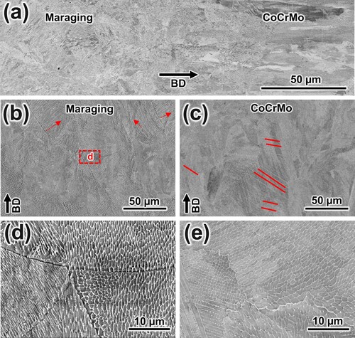
The first material to be deposited is maraging steel, and a closer look at the microstructures in (b) and (d) obtained along the building direction (BD) show familiar AM structures with melt pool boundaries that have an average width of ∼165 ± 17 μm and depth of ∼55 ± 13 μm surrounded by unevenly sized cells with an average diameter of 0.45 ± 0.1 μm and thickness of ∼75 nm. The primary cellular spacing (λ1) corresponds to an approximate cooling rate of 6.2 × 10⁶ based on the equation [Citation43,Citation44]. Due to the heat flow generated during printing, most columnar structures marked by red arrows in (b) preferentially expand perpendicular to the melt tracks and blend with the finer cells developed in the melt cores. The typical heterogenous cellular microstructure can also be recognised in the CoCrMo alloy region shown in (c) and (e). The observed melt tracks have an average width of ∼165 ± 15 μm and melt pool depth of ∼54 ± 11 μm. The cellular spacing (λ1) of 0.51 ± 0.09 μm corresponds to a cooling rate of 4.5 × 10⁶, which is very similar with maraging steel due to the small difference in thermal conductivity (13 W/m−K for CoCrMo compared to 15 W/m−K for maraging steel). Multiple groups of elongated cells that stretch along the melt tracks are mixed with spherical cells that are primarily observed inside the track cores, and the cell boundaries have a thickness of ∼80 nm. The underlying grains are predominantly columnar and exhibit epitaxial growth across multiple layers of the melted powder. Groups of parallel bands identified as ϵ-phase striations [Citation26,Citation45] and marked by red lines in (c) result in a striated structure that generally extends across melt tracks but mostly terminate along grain boundaries (some transgranular bands still exist).
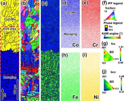
presents the phase distribution, orientation properties and kernel average misorientation (KAM) map at the interface of the freshly printed sample. A fragmented martensitic structure is observed in the maraging steel region, consisting exclusively of bcc phase with an average crystallographic lath thickness of 4.3 ± 1.2 μm. This was measured using the variant approach [Citation32,Citation46] and the distribution is shown in Supplementary Figure S2. Multiple laths show a similar alignment to both the <100>//BD and <111>//BD, but the growth of continuous blocks has been interrupted by the variable solidification conditions during printing. This results in diverse lath sizes and detached strips (marked in black in (b)) that could have fully formed under consistent thermal conditions but are instead contributing to a more refined microstructure. The underlying matrix that is influenced by the melt pool morphology still shows alignment between <100>//BD and <111>//BD, forming columnar boundaries over several layers growing epitaxially.
Figure 3. Texture development in the transition zone of the as-built sample: (a) phase map showing fcc and bcc structures, (b) inverse pole figure colour map, (c) kernel average misorientation maps, (d,e,h,i) EDS maps for Co, Cr, Fe and Ni, respectively, (f) corresponding legends for a–c, (g) IPF representation of fcc grains and (j) IPF representation of bcc grains.
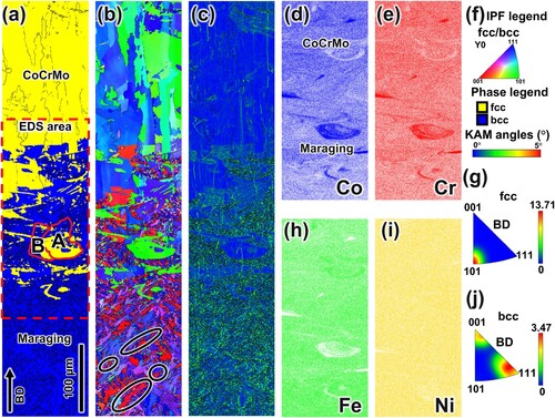
During the initial deposition of the CoCrMo layers, the liquefied region contains a mixed composition distribution from both alloys. Even though both powders dissolve to fcc phase after melting, only the maraging steel composition undergoes a bcc phase transformation during solidification. Co- and Cr-rich regions shown in EDS maps in (d) and (e) (taken from the area highlighted in (a)) had a higher tendency to retain large grain fcc regions upon cooling, while Fe-rich regions experience isolated martensitic transformation that usually results to finer laths. Segregation of Co and Cr minimises the expected martensite start temperature, leading to untransformed fcc islands in the centre of the melt. The generated circular flow also migrates Fe-rich alloying elements and allows fragmented lath solidification above the melt. The columnar structure with alloy segregation provides unique transformation conditions which form limited martensite variant types that will be identified in the discussion section. In particular, regions A and B in (a) will be analysed later for grain-scale variant distribution. Other factors, such as accumulated thermal strain, partitioning of alloying elements with differing melting temperatures, and the turbulent mixing effects of Bénard–Marangoni flow [Citation47], result in residual fcc regions in the interface that resemble the prior melt pool boundaries. In addition, the KAM maps in (c) show that the associated strain with the martensite transformation leads to areas with high concentration of low-angle KAM values, enveloping untransformed fcc regions that are essentially strain-free. Despite the difference in strain, the fcc–bcc phase boundaries display a similar distribution of KAM values with the maraging steel region. This is evident in some regions without isolated strips that have a reduced distribution of low misorientation values. After the ∼240 µm mixed-phase interface takes shape, the successive layers resemble the original CoCrMo composition. Although melt pool sizes for both materials were similar, the grains for CoCrMo are larger and columnar, averaging 92 ± 11 μm in size. A strong texture along <110>//BD and <110>//BD can be observed, which notably resembles the texture preference observed in the fcc islands along the interface.
3.2. Microstructural analysis of heat-treated samples
The applied heat treatments generated the target microstructural changes at both alloys, but unique transformation mechanisms have been observed close to the interface of the dual-metal structures. The occurrence of intermetallic precipitation is also investigated within the maraging steel region, especially since all conditions involved a 6-hour aging treatment at 490°C. Sub-sections below will present the observations from HT1, HT2 and HT3.
3.2.1. Microstructure after HT1 (1150°C for 6 h + 490°C for 6 h)
shows microstructural features within key regions of the dual-alloy specimen following HT1. Dissolution of alloying elements in both base alloys occurred at the expense of the preexisting cellular structures. In the CoCrMo region, equiaxed polygonal grains are predominant, while the maraging steel region is characterised by a hierarchical packet-block-lath structure. The major axis of martensite laths that evolved near the interface in (a) aligns with the composition gradient (parallel to the BD) and terminates at the CoCrMo grains while preserving epitaxial growth. Significant lath size evolution is evident in the maraging microstructure in (b) and (d). On the other hand, huge grains that are devoid of ϵ-hcp bands but contain annealing twins (i.e. not present in the as-printed state in ) formed in the MP1 region in (c) and (e).
Figure 4. Microstructural features after HT1: (a) transition zone, (b, d) maraging steel lath structure and (c, e) CoCrMo twin structure.
Crystallographic analysis of samples subjected to HT1 in further reveals that a well-defined phase boundary emerged at the interface, separating the bcc-phase martensite from the fcc-phase CoCrMo. Within the maraging steel region, large martensite blocks having widths averaging 7.9 ± 2.4 µm in thickness are evident. The previously observed texture and isolated martensite packets after printing have vanished, resulting in a randomised orientation distribution. High-temperature conditions facilitated stress relief and uniform alloying element distribution, thereby promoting continuous nucleation and extension across all directions. Closer to the interface in (a), the fcc islands that formerly mirrored the shape of the melt pool are no longer visible, replaced by thick martensite laths aligned along <111>//BD and extending perpendicular to the interface. Martensite packets in (b) that are far from the interface show cooperative growth and energy minimisation in all directions, but the scarcity of nucleation sites near the interface results in directional growth along the composition gradient (parallel to BD) shown in (d)–(i). The martensite laths formed a pronounced border with the CoCrMo grains, which have transformed into equiaxed grains averaging 36.7 ± 15.1 µm in size with distributed annealing twins. The CoCrMo region also exhibited a complete fcc phase that is verified by the disappearance of (110), (10
1) and (10
2) ϵ-phase XRD peaks displayed in Supplementary Figure S1a. The twin boundaries observed in the CoCrMo region satisfy the misorientation conditions for Σ3 special grain boundaries (GBs) of <111> 60°, which is further confirmed point-to-point misorientation plots in Supplementary Figure S3. The KAM maps in (c) also indicate an abrupt transition from an even spread of low-angle misorientation boundaries in the maraging steel regions, a product of the lattice distortion from martensitic transformation, to equiaxed grains devoid of local strains or low KAM values, signifying successful stress relief in the CoCrMo region. Overall, no traces of the melt pool morphology can be observed from the texture distribution in both regions, and a sharp phase transition has developed in the interface. A more comprehensive discussion of texture development after this heat treatment can be found in Ref. [Citation20].
Figure 5. Texture development in the transition zone of the HT1 sample: (a) phase map showing fcc and bcc structures, (b) inverse pole figure colour map, (c) kernel average misorientation maps, (d,e,h,i) EDS maps for Co, Cr, Fe and Ni, respectively, (f) corresponding legends for a–c, (g) IPF representation of fcc grains and (j) IPF representation of bcc grains.
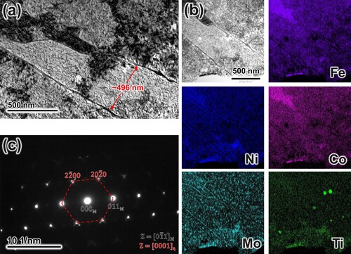
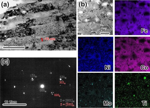
TEM characterisation results in provide additional insight into the morphology and distribution of precipitates within the maraging steel region. The disappearance of cellular walls is associated with the annihilation of entangled dislocations and the redistribution of alloying elements. Overgrown lath structures in (a) exhibit a thickness of 496.2 ± 28.1 nm, which is ∼6× the size observed in other conditions. Uniform lath growth is also accompanied by dense acicular precipitates embedded throughout the matrix, with an average length of 33.9 ± .9 nm. EDS results in (b) confirm that the precipitates coincide with Mo-enriched clusters, which is indicative of Fe7Mo6 or Fe2Mo formation. Unlike the observations made by Mei [Citation48], who linked austenite reversion to Mo-enriched precipitates after over-aging at 540°C, the preliminary solution heat treatment employed in the current study preserves a single-phase matrix after aging. Additionally, the absence of Ni segregation implies that Ni either remains unconsumed during the precipitation process or reverts back into the matrix following over-aging. Given that Ni acts as a principal austenite stabilizer capable of inducing austenite reversion in maraging steels, the suppression of the bcc-fcc phase transition is evident.
Figure 6. High resolution structures of HT1 sample: (a) TEM-BF images, (b) EDS mapping results and (c) corresponding selected area diffraction pattern.
3.2.2. Microstructure after HT2 (940°C for 2 h + 490°C for 6 h)
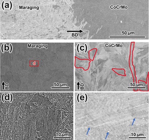
The emphasis with HT2 is to achieve high strength in maraging steel at the expense of ductility and stress relief in CoCrMo. Skipping the solution treatment step resulted in inconsistent microstructures on both regions and the interface. The microstructure morphology after HT2 is displayed in , highlighting the discontinuous martensite lath distribution in the interface. The brief exposure to 940°C gave sufficient driving force to dissolve cellular boundaries and develop lath structures in the maraging steel region, as depicted in (b) and (d). However, the cellular structure was partially retained in the CoCrMo region, as shown in (c) and (e). Additionally, this region manifested significant ϵ-hcp bands – indicated by red lines in (c) – with varying lengths and with multiple bands intersecting in highly striated regions. Some bands are transgranular and some groups of parallel bands criss-cross on top of each other. Although sharp boundaries have formed, multiple elongated grains still resemble the melt pool structure after printing. A closer look in (e) reveals the partial disintegration of the cell walls into finely dispersed and elongated boundaries. Coarse, irregularly shaped precipitates marked by blue arrows also preferentially formed along grain boundaries, which are identified as carbide precipitates through EDS.
Figure 7. Microstructural features after HT2: (a) transition zone, (b, d) maraging steel lath structure and (c, e) CoCrMo structure.
The HT2 interface features four distinct phases, two of which (fcc-Co and fcc-austenite) are indistinguishable in the phase map (see ). The non-uniform chemical distribution is reflected in the discontinuous arrangement of phases, with boundaries that resemble the original melt pool shape prior to heat treatment. For instance, the centre of the melt-shaped intermixture in (a), which preserved the fcc phase after solidification, shows Fe-depletion with Co- and Cr-enrichment based on the EDS maps in (d) and (e). Region C traced in (a) will be analysed later for grain-scale variant distribution. The predominantly fcc interface featured large columnar grains oriented along <110>//BD overlain by transformed bcc laths with a strong texture along <111>//BD and <100>//BD, tracing nucleation sites without Co and Cr segregation. Unlike the large, untransformed islands in the as-built sample, alloying element diffusion led to the formation of isolated laths inside the melt pool-shaped interface. The laths that formed at the edge of the melt also appear similarly oriented and more continuous in (b). However, the redistribution of Co and Cr led to the retention of fine fcc regions dispersed within the laths. Closer to the interface, fcc retention is more severe, with the fcc phase percentage rising to 34.3%, compared to 7.7% near the maraging steel region. Sufficient nucleation sites are available for the formation of full packets, but the inconsistent martensite structure after printing was still inherited. Avoiding solution HT also produced the thinnest block width average of 1.9 ± 0.6 µm. Large, segregated phases after printing were diffused as transformation from γ–ϵ for CoCrMo and γ–α′ for maraging steel occurred simultaneously. Furthermore, the CoCrMo region showed considerable transformation to ϵ-phase despite only 2 h of aging, showing the onset of massive transformation in unevenly sized grains that retained the original AM grain morphology. Massive transformation is an interface-controlled growth [Citation25,Citation29] that results in ϵ-hcp grains with different grain sizes and no crystallographic coherency with the previous γ grains. This agrees with the transgranular and overlapping striations observed in the microstructure. None of the grains underwent a complete transformation due to the short aging duration, resulting in a non-uniform microstructure with 16.3% ϵ-phase (15.8% from XRD results in Supplementary Figure S1a). The KAM maps in (c) display the disparity in strain distribution between regions with successful bcc/hcp conversion and those that retained the fcc phase. While the post-heat treatment interface likely exhibited limited strain initially, subsequent transformation in the maraging steel region generated strain-concentrated regions, marked by pronounced low-angle misorientations. Meanwhile, γ–ϵ phase transformation occurs through slip and features negligible misorientation with the surrounding fcc matrix.
Figure 8. Texture development in the transition zone of the HT2 sample: (a) phase map showing fcc, bcc and hcp structures, (b) inverse pole figure colour map, (c) kernel average misorientation maps, (d,e,h,i) EDS maps for Co, Cr, Fe and Ni, respectively, (f) corresponding legends for a–c, (g) IPF representation of fcc, hcp and bcc grains.
provides a closer look at the lath structure within the maraging steel region. HT2 triggers full austenitisation at 940°C but only partial disintegration of cell walls and annihilation of dislocations. As a result, lath formation is fragmented with localised strains and non-uniform composition upon quenching. Subsequent aging yields a blurred structure containing dense precipitates and dislocations forests which can be seen in (a). Laths with well-defined parallel boundaries displayed a reduced average thickness of 74.7 ± 15.8 nm, which is considerably thinner than HT1. Unlike the Mo-rich precipitates evident in HT1, EDS analysis of the HT2 specimen, shown in (b), exhibited Ni- and Ti-rich acicular precipitates with an average size of 55.2 ± 8.5 nm. The accelerated formation of Ni–Ti precipitates can be attributed to their low nucleation energy and high lattice coherency, and it is generally observed at the initial stages of aging [Citation49–51]. Preferential precipitation consumed Ni from the matrix and left islands that favour austenite nucleation, since Ni is enriched while Fe and Co remain depleted in these regions. There is a slight indication of Mo segregation but to a lesser extent compared to the ellipsoidal clusters formed in HT1. Prolonged aging could allow Fe and Mo to serve as substitutional lattice elements; however, the insufficient homogenisation likely suppressed this behaviour within the dual-phase matrix.
Figure 9. High resolution structures of HT2 sample: (a) TEM-BF images, (b) EDS mapping results and (c) corresponding SAED pattern.
3.2.3. Microstructure after HT3 (1150°C for 2 h + 940°C for 5 h + 490°C for 6 h)
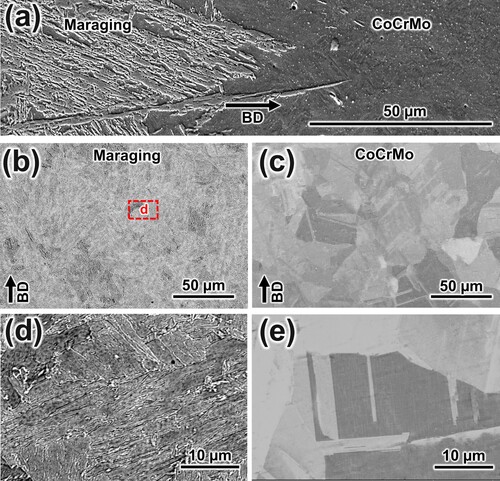
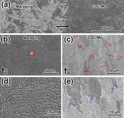
A synergistic balance between strength and ductility for both regions is desired in HT3, where CoCrMo experiences solution heat treatment and extended aging at the expense of some grain coarsening in the maraging steel region. The microstructure in shows a continuous interface in HT3, avoiding the inconsistent lath formation in HT2 and the prominent lath growth in HT1. The maraging steel region in (b) and (d) lost cellular features and traces of epitaxial growth since the initial heat treatment stages induced extensive homogenisation. Considering that the ϵ-phase transition and precipitate dissolution temperatures for CoCrMo were found at ∼970°C and ∼1140°C, respectively [Citation45], all treatment combinations effectively removed the melt tracks within the maraging steel region.
Figure 10. Microstructural features after HT3: (a) transition zone, (b, d) maraging steel lath structure and (c, e) CoCrMo structure.
The focus of HT3, however, is on altering the ϵ-phase transformation mechanism in CoCrMo. Regions highlighted in red in (c) showcase consistent, parallel ϵ-phase bands that are constrained within grains and previous melt pool boundaries. Unlike the dense striations in HT2, these bands mostly terminated at grain boundaries and displayed no overlap. The added solution treatment step preserves the previous γ grain boundaries in the succeeding γ–ϵ transformation. The presence of some equiaxed regions that include grains free of striations and containing sharp edges can also be observed. (e) displays coarse precipitates that are exclusively formed in grain boundaries, which are identified as carbide precipitates through EDS. Unlike HT2, the matrix now contains round and elongated precipitates aligned in a parallel manner. These precipitates trace the observed ϵ-hcp bands, implying that rearrangement occurred after a longer aging time.
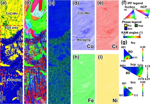
The EBSD analysis of the HT3 specimen presented in also revealed a sophisticated multi-phase interface which reflects the targeted phase transformation in both alloys. In the maraging steel region, the two-stage solution HT led to the formation of martensite blocks that are continuous and randomly oriented, with block widths averaging 2.7 ± 0.6 µm. The melt pool morphology and refined microstructure in the as-built samples disappeared. The redistribution of interface alloying elements also formed residual austenite islands scattered along bcc boundaries, shown in (a). However, austenite retention occurred to a lesser extent compared to HT2 due to the extended homogenisation observed in (d)–(i). Region D traced in (a) will be analysed later for grain-scale variant distribution. Closer to the interface, fcc retention is more severe, with the fcc phase percentage rising to 28.1%, compared to 2.7% near the maraging steel region. However, as seen in (b), lath growth persisted omni-directionally and results in a random interface texture despite the presence of four different phases. Of all the heat treatment conditions, HT3 showed the smoothest end-to-end composition and texture variation. Lath formation ceased in the interface, and large bcc martensite grains solidified in contact with both hcp and fcc-Co grains.
Figure 11. Texture development in the transition zone of the HT3 sample: (a) phase map showing fcc, bcc and hcp structures, (b) inverse pole figure colour map, (c) kernel average misorientation maps, (d,e,h,i) EDS maps for Co, Cr, Fe and Ni, respectively, (f) corresponding legends for a–c, (g) IPF representation of fcc grains, (j) IPF representation of hcp grains and (k) IPF representation of bcc grains.
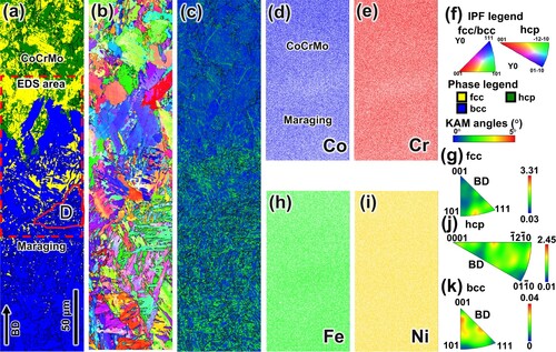
In the CoCrMo region, exposure to 940°C for 5 h caused phase transformation of γ-fcc to up to 73.6% ϵ-hcp (71.8% from XRD results in Supplementary Figure S1a). Nucleation starts at the grain boundaries and along parallel striations wherein carbide precipitates were observed in the microstructure. This suggests that local carbon depletion due to precipitation creates favourable sites for transformation. While carbon segregation at partially dissolved cell walls promoted massive transformation in HT2, the added solution treatment step in HT3 shifts the nucleation sites towards grain boundaries and parallel ϵ-hcp bands. Additionally, carbide precipitates located at these interfaces can exert a solute drag effect by impeding the migration of boundaries during the transformation process. This enables the preservation of prior γ boundaries after aging, effectively confining the expansion of ϵ-phase within individual grains. As with the other conditions, the KAM map in (c) depicts strain related to martensitic transformation in the maraging steel region. However, regions close to the fine austenite islands and large bcc grains exhibited a diminished intensity of low-angle misorientations. In the CoCrMo region, local strains between ϵ-phase bands and surrounding γ-phase grains were identified, but the hcp grains from massive transformation did not manifest any low-angle misorientations.
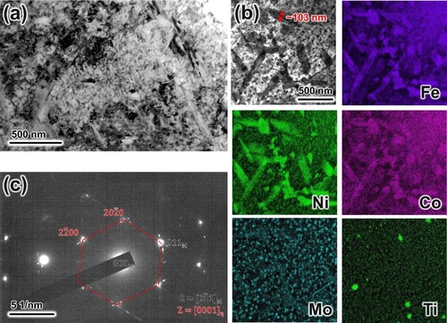
presents a detailed TEM analysis for the HT3 specimen. Lath boundaries are difficult to distinguish as they overlap with densely scattered dislocations and ultrafine precipitates. Moreover, these laths exhibit random orientations and are rarely adjacent or parallel. The prominent elongated structures enriched in Fe, Ni and Co were identified as laths, distinguished by their substantial thickness of 103.4 ± 16.7 nm—dimensions and alloy enrichment that are not typically associated with Ni-based precipitates. Additionally, they do not match the position of neither the Mo-enriched ellipsoidal precipitation clusters nor the finer acicular Ni–Ti segregation which have an average thickness of 47.6 ± 7.4 nm. During HT2, precipitation triggered Ni-enriched areas that reverted to austenite. But in the case of HT3, the depletion associated with precipitation resulted in random lath configurations that have no tendency to transform, thereby maintaining a single-phase matrix. The added benefit of the extended solution treatment is the stability of Ni3Ti nucleation despite Mo clustering and substitution. Given that the evenly distributed alloying elements counteract the depletion associated with precipitation, the results underscore the crucial role of preexisting local chemical segregation in influencing austenite reversion. HT1 and HT3 indicate that having a homogenous matrix overshadows the reversion effects of precipitate formation and subsequent Ni-depletion.
Figure 12. High resolution structures of HT3 sample: (a) TEM-BF images, (b) EDS mapping results and (c) corresponding SAED pattern.
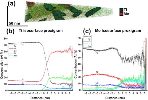
Atom probe tomography (APT) was used to further examine the formation of intermetallic precipitates that have formed during aging within the maraging steel matrix. (a) displays the 3D reconstructed volumes of solutes, featuring Ti clusters in green and Mo clusters in red, situated near a lath boundary in the HT3 sample. The corresponding iso-concentration surfaces emphasise enriched regions and corresponding proximity histograms for both precipitate types, depicted in (b) and (c) for Ti and Mo, respectively. The elongated Ti-rich precipitates show alignment in two distinct directions and can be differentiated from the blocky morphology of the Mo-rich precipitates. This observation aligns with the TEM–EDS data shown in . Upon examining the Ti clusters, which are expected to emerge at the initial stages of aging, a Ni to Ti ratio of nearly 3:1 indicative of Ni3Ti precipitation is observed. At the same time, a rise in Mo concentration within these precipitates is seen, while regions rich in Mo precipitates show a noticeable depletion of Ni instead. As can be further seen in (c), the Mo-rich clusters showed a compositional ratio between Fe + Ni + Co to Ti + Mo of approximately 2:1, hinting at a substitutional process during the formation of (Fe, Ni, Co)2(Ti, Mo). Both Ti and Mo show identical elemental percentages in this stage of aging, which suggests that the eventual Ni and Ti rejection during the formation of ellipsoidal Mo precipitates is delayed by the addition of a solution heat treatment step in HT3. This agrees with the lack of Mo-rich clusters and major precipitation of Ni3Ti in HT2, consequently leading to austenite reversion.
Figure 13. (a) Reconstructed 3D elemental distribution maps combining Ni, Ti and Mo rich precipitates. Statistical proximity histograms for (b) Ni–Ti-based Ni3Ti precipitates considering the surface value of 4.82 at.% Ti and (c) Mo-based (Fe,Ni,Co)2(Ti,Mo) considering the surface value of 4.82 at.% Mo.
3.3. Mechanical properties
depicts the nanoindentation results across the interfaces of the as-built and heat-treated conditions. The initial cross-section after LPBF shows a continuous microhardness transition, with an average of 445 ± 8 HV and 493 ± 8 HV for the CoCrMo alloy and maraging steel regions, respectively. The formation of a single-phase fcc solid solution at the interface during melting enhances the compatibility of the two alloys, eliminating the need for a gradual composition transition. The absence of unusual hardness spikes or soft regions indirectly invalidate brittle intermetallic precipitation or the formation of unwanted phases which can arise from compositional blending. Despite the inherent transient heating periods and the presence of vigorous Marangoni convection that can result in hierarchical structures [Citation52] at the interface, the fusion region only spans ∼250 μm (around 5 layers) and agrees with the EBSD results in .
Figure 14. Hardness variation in the transition zones of as-built and heat-treated specimens

After HT1, stress-relief is attained in CoCrMo and led to a decreased average hardness of 355 ± 6 HV while maraging steel undergoes strengthening precipitation that considerably increased the average hardness to 778 ± 8 HV. The joint tensile specimen had a marked increase in elongation to 27.1%, while the ultimate tensile strength was sustained at 1149 MPa. The overall chemical and microstructural consistency in both alloys created a pronounced hardness difference but low deviation across the α–γ phase boundary. The suppression of austenite reversion also contributed to minimal hardness deviation throughout the specimen. The observed hardness increase in the maraging steel region correlates with the Mo-rich clusters in , and the values remained comparable to the 820 ± 48 HV in HT2 that contains Ni, Ti-rich precipitates instead. HT2 also had a slightly elevated hardness of 474 ± 35 HV in CoCrMo due to the emergence of ϵ-hcp bands. Considerable microhardness fluctuations were recorded across ∼400 μm in the HT2 interface, which reveals the complex interplay of discontinuous lath formation, austenite reversion and retention in the maraging steel region against the partial cell disintegration, non-uniform grain morphology and massive transformation in the CoCrMo region. Although this condition attained the highest microhardness average in the maraging steel region, some level of solution treatment will be mandatory if a more stable or an isotropic component is desired.
In an attempt to improve mechanical properties for both alloys in HT3, a moderate average microhardness increase to 460 ± 24 HV and 794 ± 28 HV was detected in the CoCrMo and maraging steel regions, respectively. Reasonable deviations were observed away from the interface, which is attributed to the suppression of austenite reversion and cellular dissolution in maraging steel and evenly sized grains and ordered precipitation in CoCrMo.
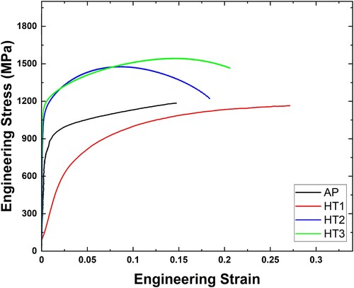
Representative engineering stress–strain curves of dual-component tensile coupons for all conditions are also presented in . The combined as-built tensile specimen revealed an ultimate tensile strength of 1162 MPa and elongation of 16.4%, which are intermediate values that lie between the strength and ductility of the base alloys [Citation20]. A marked increase in ductility to 27.1% was acquired in HT1 primarily due to recovery and stress relief in the CoCrMo region. Indicative of a homogenous structure, the maraging steel region in HT1 also exhibited Fe7Mo6 or Fe2Mo precipitation, overgrown lath structures (reduced grain boundary strengthening) and lower dislocation density due to residual stress relief, resulting in a slight decrease of tensile strength to 1149 MPa. For applications where high ductility is unnecessary, both HT2 and HT3 demonstrated enhanced mechanical properties compared to the as-built specimen. Specifically, the tensile strength for HT2 was recorded at 1489 MPa with a ductility of 17.8%, while HT3 showed the highest strength of 1511 MPa and a better ductility of 21.2%. Skipping the solution treatment step in HT2 favours dislocation hardening at the expense of ductility, while nanoscale precipitation of Ni3Ti and Fe2Mo is still expected to have the biggest impact on strengthening [Citation40]. The contribution of solid solution strengthening is also expected to decrease upon aging in all conditions as precipitation consumes the alloying elements. Although HT2 manifested the highest hardness values and confirmed dominant Ni3Ti precipitation in the maraging steel area, as evidenced by TEM and APT analysis, HT3 still had superior over-all properties. This is attributed to the additional strength provided by the considerable ϵ-hcp transformation in CoCrMo which influenced the subsequent void nucleation and coalescence. By cooperatively exploiting transformation and precipitation mechanisms in both regions, better overall strength and ductility were attained. Previous work by Antunes et al. [Citation13] have investigated the deformation-induced ϵ-hcp transformation in CoCrMo using in-situ synchrotron X-ray diffraction and TEM, highlighting interesting transformation kinetics and dislocation accumulation during loading. It is important to recognise that the primary objective of the applied treatments is not to modify the tensile properties of the combined material but to introduce beneficial improvements in the distinct mechanical properties of the base alloys. While it is still vital that the joining properties remain intact for all treatment conditions, there exists a narrow scope of potential applications for the combined component where the most critical mechanical property will be the overall tensile characteristics.
Figure 15. Engineering stress–strain curves from uniaxial tests performed on as-built and heat-treated specimens
4. Discussion
In previous works on multi-material AM components, the compatibility of CoCrMo alloy with a wide range of alloys like Ti6Al4 V [Citation17], IN718 [Citation16], 410 SS [Citation53], and others has been demonstrated. In this study, continuous printing with maraging steels showcased that thermal property and phase resemblance during melting (i.e. both fcc) led to consistent melt pool characteristics despite the use of a sharp chemical composition transition and continuous processing parameters. Focusing on the transition zone reveals the influence of chemical diffusion, vigorous convective flow and mutual redeposition to subsequent heat treatment.
One limitation in maraging steel phase transformation investigation is that it solidifies to single phase bcc after printing. However, local strain and alloy inhomogenities hindered complete transformation near the interface, allowing the retention of some information about the parent morphology. While HT2 and HT3 employ combined solution and aging temperatures, the phase distribution in the transition zone allows a new perspective on martensitic variant formation in AM components, as discussed below.
4.1. Variant selection during phase transformation in LPBF maraging steels
During martensite nucleation in low-carbon maraging steels, laths that originate from the same austenite grain will seek a final orientation that accommodates the overall minimum energy after transformation [Citation54]. This results in a random configuration of product orientations that have identical odds of aligning with any 12 or 24 possible variants when either the NW or KS OR is satisfied. Normally, groups of laths with similar orientation make up blocks, while blocks with the same habit plane are arranged into packets, forming the hierarchical packet-block-lath structure originally identified by Krauss [Citation55]. Rapid cooling rates during LPBF also convert the melt pool to a fully martensitic matrix after solidification. The XRD results from Supplementary Figure 1b, specifically from the maraging steel region, verify that a fully martensitic structure is obtained away from the Co- and Cr-rich areas in all conditions, despite the austenite reversion near the interface in both HT2 and HT3 samples. HT1 displayed similar peaks across all planes, suggesting a uniform lath orientation distribution. However, a slight preference to <011>//BD was observed in the HT2 and HT3 samples. Due to the single-phase matrix, packet and block boundaries are difficult to distinguish from the cellular structure. This prevents the straightforward identification of prior austenite morphology and texture information during EBSD analysis, prompting the need for parent reconstruction algorithms. Although the currently available pixel and grain-based reconstruction methods have improved in computational efficiency [Citation41,Citation56] and demonstrate good applicability to AM structures (most of which show the columnar nature of melt pools prior to solidification [Citation40,Citation57]), the following limitations are still a point of contention:
Every captured pixel orientation can be linked with any of the 12/24 possible variants and reconstruction can’t fully predict the preferred austenite texture prior to transformation.
Crucial insights from KAM distribution and special boundaries will not be available from parent reconstruction, rendering the investigation of dislocation density generated during printing difficult. It is also impossible to distinguish the influence of residual strains from cyclic heating to the lattice distortion associated with martensitic transformation from the original KAM maps. In particular, the lattice invariant shear generates an array of screw dislocations while entangled dislocations are inherited from the austenite matrix prior to transformation [Citation58].
The certainty that the theoretical orientation relationship holds despite the repeated phase reversion of the matrix to austenite due to iterative laser melting and solidication can not be guaranteed.
presents the variant analysis of representative grains A and B in the as-built sample highlighted in , featuring columnar grains in the interface that contain austenite islands. The fcc-phase regions have a preferred texture along <110> // BD, while the transformed bcc-phase regions were aligned along the <111> // BD and <100> // BD. The columnar sections were grouped based on orientation spread, and the average fcc orientation was used as the basis in categorising bcc laths to include in variant analysis and in predicting all theoretical variant orientations. Grain A near the melt track has an average austenite Euler orientation of φ1 = 117°, ϕ2 = 46° and φ3 = 55°, with a mean deviation of 3° while grain B near the centre of the melt pool has an average austenite orientation of φ1 = 89°, ϕ2 = 43° and φ3 = 1°, with a mean deviation of 4°. (a) and (d) depict the pole figure representation of the {100}γ orientations in the respective grains, revealing a low deviation. The corresponding martensite {100}α orientations within each austenite grain were also projected and coloured in gray in pole figures in (b) and (e). A comparison with the previous {100}γ pole figures reveal that the {100}α projections surround the {100}γ positions and form localised orientation clusters, indicating that a transformation relationship is preserved within the grain. To investigate the orientation distribution between the two phases, (e) and (f) compare the positions of predicted variants (governed by the aforementioned ORs) against the experimental martensite orientations. Also included are the KS and NW variants represented by blue circles and red triangles, respectively. The Bishop–Hill nomenclature [Citation59,Citation60] was used to label the KS variants, wherein each variant is classified based on the densely-packed {111}γ plane parallellism condition. The letters a, b, c and d are designated to the (111), (1), (11) and (1
1) planes, respectively while the subscripts I, II and III denote the Burgers vectors corresponding to type <01
>, <101> and <1
0> directions, respectively [Citation59,Citation60]. The {100}α in gray are then superimposed on the predicted variants. The entire pole figure was rotated so that the [1
0] and [
2] planes of the γ projections are oriented along the x- and y-axes, respectively. This arrangement provides a clear illustration of the variant distribution using the three Bain circles surrounding the γ projections [Citation54].
Figure 16. Pole figure analysis of Grain A (a–c) and Grain B (d–f) in as-built samples: (a, d) band contrast with fcc phase IPF colour map (left) and corresponding {100}γ pole figures (right), (b, e) band contrast with bcc phase IPF colour map (left) and corresponding {100}γ pole figures (right), (c, f) band contrast with phase map (left) and comparison of {100}α to the predicted K–S and N–W variants projected along the {111}γ plane.
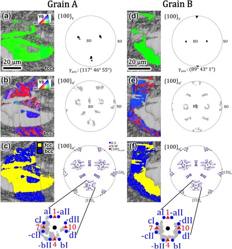
Grain-scale variant selection is already evident near the melt track in Section A ((a)), where none of the {100}α projections coincided with six KS variants (-aII, -dII, aII, dII, -dI, -aI) and two NW variants (1 & 12). Closer to the centre of the melt pool in Section B ((d)), fewer KS variants (aI, -aII, aII, -aI) and only the NW variant 1 are missing. Previous studies have linked variant selection to plastic deformation substructures and slip activity [Citation61]. However, the preliminary findings in this study show that residual stress and recoil pressure from thermal cycling can also contribute to this phenomenon. The Marangoni flow driven by surface tension differences also appears to alleviate variant selection during solidification, since fewer variants are missing at the edge of the melt pool compared to the centre, and a more vigorous convective flow and high thermal gradient are expected at the edges. Studies in melt flow physics [Citation62] have subdivided the melt track according to the predominant forces acting in various regions, namely the `depression region` set at the laser spot (Grain A) and the `tail end` region located at the end of the melt track (Grain B). This classification can be relevant to the variant selection observed in this study, since recoil forces are more dominant in the depression region corresponding to grain A (where variant selection is more severe) compared to the tail end region where surface tension is more dominant, corresponding to grain B.
Additionally, some {100}α projections preferentially aligned with specific variants in both A and B, with certain measurements spread considerably far from the Bain Circle predictions. Previous welding simulations have reported no variant selection despite a high cooling rate [Citation63]. However, this study shows that if the solidification involves repeated reversion and limited transgranular transformation, which is the case for LPBF, the laths can assume final orientations that have considerable discrepancy from the expected plane and direction parallelism conditions.
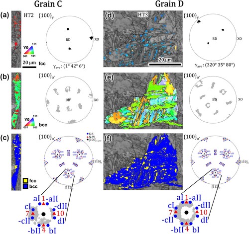
Only HT2 and HT3 exhibited the presence of retained/reverted austenite within martensitic grains, which is necessary for variant analysis without reconstruction. Accordingly, showcases the variant analysis of two representative grains: Grain C from the HT2 interface in and Grain D from the HT3 interface in . The austenite regions within grain C had an average orientation of φ1 = 1°, ϕ2 = 42° and φ3 = 6°, with an average spread of 5°. The columnar morphology from AM is retained in HT2 since the solution treatment step is skipped. Interestingly, not only did the cell structure in HT2 persist but they also inherited some of the missing variants from the as-built samples. Similar to grain A, four KS variants (a1, -aII, aII, dII) and NW variant 1 did not coincide with any of the {100}α projections. On the other hand, the austenite regions in grain D had an average orientation of φ1 = 320°, ϕ2 = 35° and φ3 = 80° with an average spread of 4°. The surrounding martensitic laths in HT3 did not resemble the prior cellular structures and exhibited a random orientation configuration despite the presence of retained austenite. Moreover, the {100}α projections are evenly distributed among all 24 KS variants and 12 NW variants, eliminating any hints of variant selection. The analysis reveals that recrystallisation and complete solution treatment above the Ae3 line are necessary to allow the formation of all possible lath configurations in approximately equal volume fractions. Austenitising beyond the Ae1 boundary in HT2 is inadequate in preserving all potential martensitic variants.
Figure 17. Pole figure analysis of Grain C (a–c) from HT2 and Grain D (d–f) from HT3: (a, d) band contrast with fcc phase IPF colour map (left) and corresponding {100}γ pole figures (right), (b, e) band contrast with bcc phase IPF colour map (left) and corresponding {100} α’ pole figures (right), (c, f) band contrast with phase map (left) and comparison of {100}α’ to the predicted K–S and N–W variants projected along the {111}γ plane.
4.2. Comparison of three heat treatment schedules
While HT1 is a solution treatment previously applied to CoCrMo alloys, the impact of prolonged exposure at elevated temperatures has relatively been unexplored for maraging steels made with L-PBF. Previous studies have identified the considerable influence of increasing the austenitising temperature on grain size [Citation64], which was also confirmed through morphological and crystallographic comparison in this study. The continuous phase boundary in HT1 shows that sufficient solution temperatures counteract residual thermal stress and segregation effects from solidification, leading to ductility improvement while retaining tensile strength. The influence of solution treatment on the nucleation of intermetallic precipitates in maraging steel was also revealed, showing a single-phase matrix with Mo-enriched clusters.
In HT2, enhanced mechanical properties and a marked increase in hardness were observed due to a combination of dispersed acicular precipitates that trigger secondary hardening and the presence of thermally stable reverted austenite that contributes to enhanced toughness and strain-induced hardening [Citation65]. The emergence of Ni- and Ti-rich precipitates is coherent with the bcc phase and provides additional energy in impeding dislocation movement [Citation11], which in turn facilitates preferential nucleation and subsequent alloy depletion upon continued aging. Chemical segregation remains evident close to the interface, promoting preferred austenite growth in regions with Co and Cr amounts above the bulk composition. Although other reports on cell wall segregation did not necessarily convert to fcc phase after solidification [Citation66], the rearrangement of dislocation forests further led to fragmented lath formation. Investigations on austenite reversion at elevated temperatures differentiated the role of substitutional elements to the rate of austenite stabilisation with the role of interstitial movement with intermetallic precipitation and dislocation distribution [Citation67,Citation68].
HT3 principally employed a dual-stage solution treatment to maraging steel with the objective of optimising the properties of the CoCrMo region. The unintended benefit of extending the solution treatment in HT3 is the stabilisation of Ni3Ti precipitates, which coexisted with Mo-rich precipitates. A better over-all strength and ductility are achieved by maximising strengthening mechanisms from both alloys. The examination of the maraging steel region also revealed acicular and ellipsoidal precipitates within a single-phase matrix.
5. Conclusions
This work analysed the impacts of continuous LPBF and heat treatments on the mechanical behaviour and microstructural characteristics of a CoCrMo alloy-maraging steel dual structure. The main conclusions are summarised as follows:
The transition zone of as-built specimens exhibited phase compatibility, fragmented lath formation and austenite retention in Co and Cr-rich regions, creating the ideal environment for γ-α′ phase transformation investigation. Thermal cycling triggers grain-scale martensite variant selection and considerable deviation from the Bain Circle predictions, attributed to residual stress and recoil pressure that is aggravated in the centre of the melt. This phenomenon is alleviated close to the melt pool boundaries due to vigorous convective flow.
Prolonged solution treatment and aging in HT1 (1150°C for 6 h + 490°C for 6 h) generated coherent twins and enhanced ductility in CoCrMo. Ellipsoidal Mo-rich precipitates and substantial lath size evolution are also observed within maraging steel. A distinct fcc-bcc phase boundary emerged in the transition zone due to chemical homogenisation.
Peak strength in the maraging steel region is achieved during HT2 (940°C for 2 h + 490°C for 6 h), primarily due to Ni3Ti precipitation. However, Ni depletion and non-uniform chemical distribution lead to austenite reversion and the disappearance of the same variants that are absent in the as-built sample. A two-hour aging treatment at 940°C is sufficient for γ–ϵ massive transformation to occur within CoCrMo.
HT3 (1150°C for 2 h + 940°C for 5 h + 490°C for 6 h) generated the smoothest end-to-end composition, texture and hardness variation among all heat treatment schedules, which is correlated with the dissolution of cellular structures and complete martensite variant evolution. Achieving the highest tensile strength is attributed to cooperative strengthening from intermetallic precipitation in maraging steel and significant γ–ϵ transformation in CoCrMo.
A uniform chemical distribution in the matrix mitigates the occurrence of austenite reversion and overshadows the influence of precipitation-induced alloy depletion on austenite transformation.
nvpp_a_2372629_sm1633.docx
Download MS Word (1.2 MB)Acknowledgements
The authors acknowledge the funding received from the Natural Sciences and Engineering Research Council of Canada (NSERC), the Canada Foundation for Innovation (CFI) and the New Brunswick Innovation Foundation (NBIF).
Disclosure statement
No potential conflict of interest was reported by the author(s).
Data availability statement
The data that support the findings of this study are available from the corresponding author upon reasonable request.
Additional information
Funding
References
- Cheung KC, Gershenfeld N. Reversibly assembled cellular composite materials. Science. 2013;341:1219–1221. doi:10.1126/science.1240889
- Vaezi M, Chianrabutra S, Mellor B, et al. Multiple material additive manufacturing – Part 1: a review. Virtual Phys Prototyp. 2013;8:19–50. doi:10.1080/17452759.2013.778175
- Sing SL, Huang S, Goh GD, et al. Emerging metallic systems for additive manufacturing: in-situ alloying and multi-metal processing in laser powder bed fusion. Prog Mater Sci. 2021;119:38–45. doi:10.1016/j.pmatsci.2021.100795
- Liu Y, Sing SL. A review of advances in additive manufacturing and the integration of high-performance polymers, alloys, and their composites. Mater Sci Addit Manuf. 2023;2:2–6. doi:10.36922/msam.1587
- Wang D, Liu L, Deng G, et al. Recent progress on additive manufacturing of multi-material structures with laser powder bed fusion. Virtual Phys Prototyp. 2022;17:329–365. doi:10.1080/17452759.2022.2028343
- Wei C, Li L. Recent progress and scientific challenges in multi-material additive manufacturing via laser-based powder bed fusion. Virtual Phys Prototyp. 2021;16:347–371. doi:10.1080/17452759.2021.1928520
- Zhou K, Hnkan C. Powder-based additive manufacturing: Materials, techniques and applications, 2021.
- Zheng D, Li R, Kang J, et al. Achieving superelastic shape recoverability in smart flexible CuAlMn metamaterials via 3D printing. Int J Mach Tools Manuf. 2024;195:1–3. doi:10.1016/j.ijmachtools.2023.104110
- Nyamuchiwa K, Palad R, Panlican J, et al. Recent progress in hybrid additive manufacturing of metallic materials. Appl Sci. 2023;13:9–16. doi:10.3390/app13148383
- Han R, Li X, Chen H, et al. Microstructure evolution and mechanical properties of TiB2/18Ni300 composite material produced by laser additive manufacturing. J Mater Res Technol. 2023;24:4517–4533. doi:10.1016/j.jmrt.2023.04.043
- Niu M, Zhou G, Wang W, et al. Precipitate evolution and strengthening behavior during aging process in a 2.5 GPa grade maraging steel. Acta Mater. 2019;179:296–307. doi:10.1016/j.actamat.2019.08.042
- Haftlang F, Seol JB, Zargaran A, et al. Chemical core-shell metastability-induced large ductility in medium-entropy maraging and reversion alloys. Acta Mater. 2023;256:1–6. doi:10.1016/j.actamat.2023.119115
- Antunes LHM, Hoyos JJ, Andrade TC, et al. Deformation-induced martensitic transformation in Co-28Cr-6Mo alloy produced by laser powder bed fusion: Comparison surface vs. bulk. Addit Manuf. 2021;46:3–8. doi:10.1016/j.addma.2021.102100
- Coutinho Saraiva BR, Novotný L, Carpentieri B, et al. Effect of cyclic loading on microstructure and crack propagation in additively manufactured biomaterial Co–Cr–Mo alloy. J Mater Res Technol. 2023;26:3905–3916. doi:10.1016/j.jmrt.2023.08.185
- Groden C, Champagne V, Bose S, et al. Inconel 718-CoCrMo bimetallic structures through directed energy deposition-based additive manufacturing. Mater Sci Addit Manuf. 2022;1:2–5. doi:10.18063/msam.v1i3.18
- Wen Y, Zhang B, Narayan RL, et al. Laser powder bed fusion of compositionally graded CoCrMo-Inconel 718. Addit Manuf. 2021;40:1–5. doi:10.1016/j.addma.2021.101926
- Bartolomeu F, Carvalho O, Gasik M, et al. Multi-functional Ti6Al4V-CoCrMo implants fabricated by multi-material laser powder bed fusion technology: a disruptive material’s design and manufacturing philosophy. J Mech Behav Biomed Mater. 2023;138:2–6. doi:10.1016/j.jmbbm.2022.105583
- Ben-Artzy A, Reichardt A, Borgonia J-P, et al. Compositionally graded SS316 to C300 maraging steel using additive manufacturing. Mater Des. 2021;201:3–9. doi:10.1016/j.matdes.2021.109500
- Bai Y, Zhao C, Zhang Y, et al. Microstructure and mechanical properties of additively manufactured multi-material component with maraging steel on CrMn steel. Mater Sci Eng A. 2021;802:4–8. doi:10.1016/j.msea.2020.140630
- Pasco J, Tian Y, Chadha K, et al. Unusual interface phase transformation during continuous additive manufacturing of maraging steel and Co–30Cr–7Mo alloy. Mater Sci Eng A. 2023;881:2–11. doi:10.1016/j.msea.2023.145336
- Niu MC, Yin LC, Yang K, et al. Synergistic alloying effects on nanoscale precipitation and mechanical properties of ultrahigh-strength steels strengthened by Ni3Ti, Mo-enriched, and Cr-rich co-precipitates. Acta Mater. 2021;209:4–13. doi:10.1016/j.actamat.2021.116788
- Wang X, Li W, Yao Y, et al. In-situ alloyed ultrahigh strength steels via additive manufacturing. Addit Manuf. 2023;77:3–10. doi:10.1016/j.addma.2023.103825
- Schneck M, Horn M, Schmitt M, et al. Review on additive hybrid- and multi-material-manufacturing of metals by powder bed fusion: state of technology and development potential. Prog Addit Manuf. 2021;6:881–894. doi:10.1007/s40964-021-00205-2
- Rao J, Sing SL, Lim JCW, et al. Detection and characterisation of defects in directed energy deposited multi-material components using full waveform inversion and reverse time migration. Virtual Phys Prototyp. 2022;17:1047–1057. doi:10.1080/17452759.2022.2086142
- Kurosu S, Matsumoto H, Chiba A. Isothermal phase transformation in biomedical Co-29Cr-6Mo alloy without addition of carbon or nitrogen. Metall Mater Transact A. 2010;41:2613–2625. doi:10.1007/s11661-010-0273-8
- Roudnická M, Kubásek J, Pantělejev L, et al. Heat treatment of laser powder-bed-fused Co–28Cr–6Mo alloy to remove its microstructural instability by massive FCC→HCP transformation. Addit Manuf. 2021;47:2–8. doi:10.1016/j.addma.2021.102265
- Mori M, Yamanaka K, Chiba A. Phase decomposition in biomedical Co–29Cr–6Mo–0.2N alloy during isothermal heat treatment at 1073K. J Alloys Compd. 2014;590:411–416. doi:10.1016/j.jallcom.2013.12.126
- Takaichi A, Kajima Y, Kittikundecha N, et al. Effect of heat treatment on the anisotropic microstructural and mechanical properties of Co–Cr–Mo alloys produced by selective laser melting. J Mech Behav Biomed Mater. 2020;102:5–9. doi:10.1016/j.jmbbm.2019.103496
- Donkor BT, Song J, Fu Y, et al. Accelerated γ-face-centered cubic to ϵ-hexagonal close packed massive transformation in a laser powder bed fusion additively manufactured Co-29Cr-5Mo alloy. Scr Mater. 2020;179:65–69. doi:10.1016/j.scriptamat.2020.01.012
- Kurosu S, Nomura N, Chiba A. Microstructure and Mechanical Properties of Co-29Cr-6Mo Alloy Aged at 1023 K. Mater Trans. 2007;48:1517–1522. doi:10.2320/matertrans.MRA2007606
- Putaux J-L, Chevalier J-P. HREM study of self-accommodated thermal ϵ-martensite in an Fe-Mn-Si-Cr-Ni shape memory alloy. Acta Mater. 1996;44:1701–1716. doi:10.1016/1359-6454(95)00268-5
- Nyyssönen T, Gazder AA, Hielscher R, et al. Habit plane determination from reconstructed parent phase orientation maps. Acta Mater. 2023;255:3–11. doi:10.1016/j.actamat.2023.119035
- Bain EC, Dunkirk NY. The nature of martensite. Trans AIME. 1924;70:25–47.
- Ray RK, Jonas JJ. Transformation textures in steels. Int Mater Rev. 1990;35:1–36. doi:10.1179/095066090790324046
- Jonas JJ, He Y, Godet S. Representation of misorientations in Rodrigues-Frank space: application to the Bain, Kurdjumov-Sachs, Nishiyama-Wassermann, Pitsch and Greninger-Troiano orientation relationships. Mater Sci Forum. 2005;495-497:1177–1182. doi:10.4028/www.scientific.net/MSF.495-497.1177
- Godet S, Glez JC, He Y, et al. Grain-scale characterization of transformation textures. J Appl Crystallogr. 2004;37:417–425. doi:10.1107/S0021889804007320
- He Y, Godet S, Jacques PJ, et al. Crystallographic relations between face- and body-centred cubic crystals formed under near-equilibrium conditions: observations from the Gibeon meteorite. Acta Mater. 2006;54:1323–1334. doi:10.1016/j.actamat.2005.11.008
- Truong TD, Asala G, Ola OT, et al. Effects of additive manufacturing process parameters and heat treatment on texture evolution and variant selection during austenite-martensite transformation in 18%Ni-M350 maraging steel. Mater Charact. 2023;204:4–7. doi:10.1016/j.matchar.2023.113190
- Zhang M, Yang Y, Song C, et al. An investigation into the aging behavior of CoCrMo alloys fabricated by selective laser melting. J Alloys Compd. 2018;750:878–886. doi:10.1016/j.jallcom.2018.04.054
- Wei S, Kumar P, Lau KB, et al. Effect of heat treatment on the microstructure and mechanical properties of 2.4 GPa grade maraging steel fabricated by laser powder bed fusion. Addit Manuf. 2022;59:2–11. doi:10.1016/j.addma.2022.103190
- Niessen F, Nyyssönen T, Gazder AA, et al. Parent grain reconstruction from partially or fully transformed microstructures inMTEX. J Appl Crystallogr. 2022;55:180–194. doi:10.1107/S1600576721011560
- Miller MK, Forbes RG. Atom-probe tomography: the local electrode atom probe. Boston, MA: Springer US; 2014. doi:10.1007/978-1-4899-7430-3
- Tan C, Zhou K, Ma W, et al. Interfacial characteristic and mechanical performance of maraging steel-copper functional bimetal produced by selective laser melting based hybrid manufacture. Mater Des. 2018;155:77–85. doi:10.1016/j.matdes.2018.05.064
- Schubert Th, Löser W, Schinnerling S, et al. Alternative phase formation in thin strip casting of stainless steels, Mater Sci Technol. 11 (1995) 181–185. doi:10.1179/mst.1995.11.2.181
- López HF, Saldivar-Garcia AJ. Martensitic transformation in a Cast Co-Cr-Mo-C alloy. Metall Mater Transact A. 2008;39:8–18. doi:10.1007/s11661-007-9370-8
- Hielscher R, Nyyssönen T, Niessen F, et al. The variant graph approach to improved parent grain reconstruction. Materialia. 2022;22:4–9. doi:10.1016/j.mtla.2022.101399
- Liu X, Zhou X, Xu B, et al. Morphological development of sub-grain cellular/bands microstructures in selective laser melting. Materials (Basel). 2019;12:3–6. doi:10.3390/ma12081204
- Mei X, Yan Y, Fu H, et al. Effect of aging temperature on microstructure evolution and strengthening behavior of L-PBF 18Ni(300) maraging steel. Addit Manuf. 2022;58:4–8. doi:10.1016/j.addma.2022.103071
- Allam T, Pradeep KG, Köhnen P, et al. Tailoring the nanostructure of laser powder bed fusion additively manufactured maraging steel. Addit Manuf. 2020;36:1–6. doi:10.1016/j.addma.2020.101561
- Jägle EA, Choi P-P, Van Humbeeck J, et al. Precipitation and austenite reversion behavior of a maraging steel produced by selective laser melting. J Mater Res. 2014;29:2072–2079. doi:10.1557/jmr.2014.204
- Tan C, Zhou K, Ma W, et al. Microstructural evolution, nanoprecipitation behavior and mechanical properties of selective laser melted high-performance grade 300 maraging steel. Mater Des. 2017;134:23–34. doi:10.1016/j.matdes.2017.08.026
- Dong Z, Han C, Zhao Y, et al. Role of heterogenous microstructure and deformation behavior in achieving superior strength-ductility synergy in zinc fabricated via laser powder bed fusion. Int J Extreme Manuf. 2024;6:2–5. doi:10.1088/2631-7990/ad3929
- Traxel KD, Bandyopadhyay A. First Demonstration of Additive Manufacturing of Cutting Tools using Directed Energy Deposition System: Stellite™-Based Cutting Tools. Addit Manuf. 2019;25:460–468. doi:10.1016/j.addma.2018.11.019
- He Y, Jonas JJ, Godet S, et al. Crystallographic features of theγ-to-α transformation in a Nb-added transformation-induced plasticity steel. Metall Mater Transact A. 2006;37:2641–2653. doi:10.1007/BF02586099
- Krauss G. Steels: heat treatment and processing principles. Materials Park (OH): ASM International; 1989; https://cir.nii.ac.jp/crid/1130000798012046336 (accessed October 9, 2023).
- Kubota M, Ushioda K, Miyamoto G, et al. Analysis of recrystallization behavior of hot-deformed austenite reconstructed from electron backscattering diffraction orientation maps of lath martensite. Scr Mater. 2016;112:92–95. doi:10.1016/j.scriptamat.2015.09.020
- Saville AI, Vogel SC, Creuziger A, et al. Texture evolution as a function of scan strategy and build height in electron beam melted Ti-6Al-4V. Addit Manuf. 2021;46:1–8. doi:10.1016/j.addma.2021.102118
- T. Maki. 2 - Morphology and substructure of martensite in steels. In: E Pereloma, DV Edmonds, editors, Phase transform. Steels: Woodhead Publishing; 2012: p. 34–58. doi:10.1533/9780857096111.1.34
- Bishop J.F.W., Hill R. A theory of the plastic distortion of a polycrystalline aggregate under combined stresses, London, Edinburgh, Dublin Philos Mag J Sci. 42 (1951) 414–427. doi:10.1080/14786445108561065
- Bishop J.F.W., Hill R. A theoretical derivation of the plastic properties of a polycrystalline face-centred metal, London Edinburgh Dublin Philos Mag J Sci. 42 (1951) 1298–1307. doi:10.1080/14786444108561385
- Sum M, Jonas JJ. A dislocation reaction model for variant selection during the austenite-to-martensite transformation. Texture Stress Microstruct. 1999;31:187–215. doi:10.1155/TSM.31.187
- Khairallah SA, Anderson AT, Rubenchik A, et al. Laser powder-bed fusion additive manufacturing: physics of complex melt flow and formation mechanisms of pores, spatter, and denudation zones. Acta Mater. 2016;108:36–45. doi:10.1016/j.actamat.2016.02.014
- He YL, Godet S, Jacques PJ, et al. Crystallographic relationships between FCC and BCC crystals: a study using EBSD techniques. Solid State Phenomena. 2005;105:121–126. doi:10.4028/www.scientific.net/SSP.105.121
- Olson GB, Cohen M. A general mechanism of martensitic nucleation: Part I. General concepts and the FCC → HCP transformation. Metall Trans A. 1976;7:1897–1904. doi:10.1007/BF02659822
- Conde FF, Escobar JD, Oliveira JP, et al. Austenite reversion kinetics and stability during tempering of an additively manufactured maraging 300 steel. Addit Manuf. 2019;29:3–7. doi:10.1016/j.addma.2019.100804
- Kürnsteiner P, Wilms MB, Weisheit A, et al. Massive nanoprecipitation in an Fe-19Ni-xAl maraging steel triggered by the intrinsic heat treatment during laser metal deposition. Acta Mater. 2017;129:52–60. doi:10.1016/j.actamat.2017.02.069
- Conde FF, Avila JA, Oliveira JP, et al. Effect of the as-built microstructure on the martensite to austenite transformation in a 18Ni maraging steel after laser-based powder bed fusion. Addit Manuf. 2021;46:3–9. doi:10.1016/j.addma.2021.102122
- dos Santos LPM, Béreš M, de Castro MO, et al. Kinetics of reverted austenite in 18 wt.% Ni grade 300 maraging steel: an in-situ synchrotron X-ray diffraction and texture study. JOM. 2020;72:3502–3512. doi:10.1007/s11837-020-04254-w