
 ?Mathematical formulae have been encoded as MathML and are displayed in this HTML version using MathJax in order to improve their display. Uncheck the box to turn MathJax off. This feature requires Javascript. Click on a formula to zoom.
ABSTRACT
Metal powders are essential for additive manufacturing (AM), with their morphology significantly impacting the performance of AM components. Gas atomisation (GA) is a common method for producing metal powders due to its efficiency and cost-effectiveness. However, GAed powders often exhibit defects such as alien powders, satellite powders, and hollow powders, which can adversely affect the AM process. To address these challenges, coaxial gas technology has been introduced and analysed through numerical simulation. Our study involved comparing GA processes with and without coaxial gas technology to generate two types of powders. These powders were assessed using Synchrotron X-ray computed tomography (SXCT) and classification algorithms. The pores in AM components manufactured from these powders were examined using SXCT, and their mechanical properties were evaluated through tensile tests. The findings of our research validate the effectiveness of coaxial gas technology in reducing powder defects and enhancing the performance of AM components.
Introduction
Metal powders are crucial raw materials in additive manufacturing (AM) and are utilised in various AM technologies [Citation1–3]. Gas atomisation (GA) is the primary method for producing metal powders due to its low cost and high efficiency. Approximately 50% of metal powders for AM technology are produced using GA technology, as GAed powders exhibit high purity, low oxygen content, controllable particle size, low cost, and high sphericity, making them suitable for AM technologies [Citation4–6]. However, GAed powders have defects such as hollow powder, alien powder, and satellite powder, which directly impact the tap density and flowability of powders [Citation7–10]. These defects can adversely affect the AM process by causing pores in components [Citation11–14]. Directed Energy Deposition (DED) and Laser Powder Bed Fusion (LPBF) are common additive manufacturing processes used to fabricate 3D objects by adding material layer by layer [Citation15–17]. The particle size distribution (PSD) requirements for the two technologies differ, with LPBF requiring a PSD range from 15 to 53 μm, while DED requires a range of 53–105 μm [Citation15,Citation18–21].
To optimise the GA process, numerous researchers have explored the correlation between PSD and various technological parameters and nozzle structures [Citation22–24]. Some studies have focused on identifying powder defects and understanding their formation mechanisms through simulations, proposing measures to mitigate them [Citation25–27]. However, while these studies provide valuable insights, they usually lack the necessary qualification data and experimental results to validate the effectiveness of these measures. Therefore, there is an urgent need to qualify the powder morphology to accurately assess the quality of these powders.
Common methods for characterising powder morphology include qualitative observation using scanning electron microscopy and inspecting inner powder pores in 2D through optical microscopy by polishing the powders in an inlay sample [Citation21,Citation28–30]. While bulk powder testing methods like measuring tap density and flowability provide some understanding of powder morphology, they may not offer a comprehensive evaluation [Citation31]. Synchrotron X-ray computed tomography (SXCT) emerges as a valuable technique for characterising powder morphology, as it enables 3D reconstruction and utilises image processing technology to derive morphological parameters and 3D images of powders [Citation32,Citation33]. While some research has utilised SXCT to analyse the morphology of GAed powders, there remains a gap in applying this technique to assess powder morphology used in AM technology. Previous studies compared water-atomised powder and GAed powders in LPBF, as the water-atomised powder is not commonly employed in AM processes [Citation4,Citation34]. Furthermore, certain classifications of powders based on morphological features overlook critical aspects like porosity, leading to oversimplified categorizations.
Several studies have examined the impact of coaxial gas and demonstrated the formation mechanism of satellite powders through GA simulations. While some research used horizontal gas flow to control particle flow and reduce collision probability [Citation23], others employed close-coupled twin-nozzles to eliminate nearby vortexes [Citation35]. However, these studies primarily analysed powder morphology using SEM and PSD results, without conducting quantitative analysis of inner pores within the powders. Additionally, the focus of these papers was on simulating gas flow or two-phase flow in the gas atomisation process, overlooking powder flow analysis. Our methodology utilised vertical coaxial gas flow to eliminate the vortex, presenting a different approach to coaxial gas technology.
In our research, the numerical simulation of the Discrete Particle Model(DPM) is used to reveal the formation of the powder defects. We have produced two types of powders using GA with and without coaxial gas technology, which were utilised in both LPBF and DED processes. By employing the SXCT method, incorporating 3D reconstruction techniques, considering morphological parameters, and utilising machine learning, we have accurately quantified defects in the powders. The combination of SXCT technology and tensile tests is used to evaluate pore distribution and the performance of the AMed samples. Our results demonstrate the efficacy of coaxial gas technology in reducing powder defects and improving the performance of AMed components.
Method
The study investigated the impact of coaxial gas technology on powder morphology in GA and the performance of AMed components using two types of powders: non-optimal powders without coaxial gas technology, which exhibit more defects, and optimal powders with coaxial gas technology, showing fewer defects. These powders were applied in the DED and LPBF processes. The morphology of the powders and samples from DED and LPBF was assessed using SXCT technology, with morphological parameters obtained through 3D reconstruction technology. Tensile tests were then conducted to assess the performance of these samples.
Samples and facilities preparation
The GAed powders of AlSi10Mg are produced by the GA facility of our team [Citation36], with the primary elements detailed in .
Table 1. the contents of AlSi10Mg.
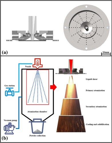
The two types of GAed powders produced by two different GA technologies were selected as samples for our work, as depicted in . The GA process without coaxial gas technology is shown in (a), where the presence of a vortex can result in the backflow of numerous small powders and collisions in the atomisation zone, leading to an increase in powder defects. The SEM images of these powders are shown in (c) and (e), revealing many small powders bonding to the surface of the powders, which we refer to as the non-optimal powder in our study. On the other hand, the GA process with coaxial gas technology is illustrated in (b), where the coaxial gas helps to control the vortex, ultimately reducing powder defects. The SEM images of these powders are displayed in (d) and (f), exhibiting smooth surfaces of the powders, which we classify as the optimal powder in our research. These classifications are simply meant to distinguish between the two types of GAed powders and are not directly related to powder morphology. The GA technological parameters are detailed in .
Figure 1. (a) the schematic diagram of the GA process without coaxial gas, (b) the schematic diagram of the GA process with coaxial gas, (c) the non-optimal powders for DED, (d) the optimal powders for DED,(e) the non-optimal powders for LPBF,(f) the optimal powders for LPBF.
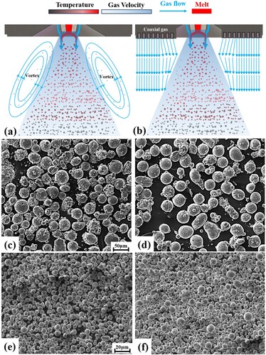
Table 2. The technological parameters of GA.
The powder samples for SXCT are enclosed in 0.2 ml centrifuge tubes mixed with resin, as shown in (a). These powder samples are employed in LPBF and DED processes and then transformed into bulk samples. Wire Electrical Discharge Machining is utilised to shape these bulk materials into tensile samples, as illustrated in (b). The process parameters for DED and LPBF have been optimised through various experiments, with specific details provided in . Tensile samples manufactured by AM undergo tensile testing using a universal tensile testing machine, with three samples prepared for each AM process to minimise experimental uncertainties. The preload setup for the tensile test is 45 N, and the tensile speed is set to 0.0001 s−1.
Figure 2. (a) the geometry of centrifuge tubes, (b) the geometry of the tensile sample, (c) the setup of SXCT facility, (d) the layout of SXCT, (e) the layout of the sample.
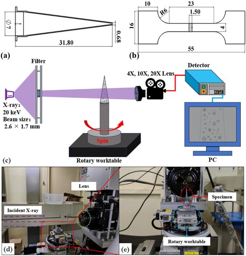
Table 3. The technological parameters of AM.
The SXCT was performed at the BL13W beamline at Shanghai Synchrotron Radiation Facility (SSRF) China. The configurations facility is shown in (c-e), and the setup of our experiment is listed in , Each sample was rotated over 180° and 1500 projection images were taken at an increment of 0.2° during scanning with an exposure time of 5 s.
Table 4. The setup of SXCT.
The method of figure processing and morphological parameters
All images acquired through SXCT require phase recovery and projection processing using the PITRE software to generate slice images. Subsequently, all slices are imported into Avizo 3D software, where the brightness and contrast are adjusted to enhance the differentiation between the background and powders or pores. The slices of powders or pores undergo 3D reconstruction to accurately depict their morphology. The label analysis tool of the Avizo 3D software enables the segmentation of objects and the extraction of a series of morphological parameters based on user requirements.
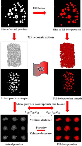
However, Avizo 3D is unable to calculate the pore size in powders, but it can be obtained using other methods. Here, we present a method for reconstructing the pore size in powders. The schematic diagram is shown in . Firstly, we obtain the morphological parameters of all powders except for the pore size. Then, we use the ‘fill hole’ function to fill in the holes and proceed with 3D reconstruction to obtain all morphological parameters of solid powders without pores. Since these 3D reconstructions are in the same coordinate system, the coordinate differences of the centre of mass are minimal in the distance between target powder and correspondent fill-hole powder, which can be expressed by the following equation:
where
,
and
are the positions of the target powder,
,
and
are the position of each fill-hole powder of the sample.
is the distance between the target powders and all fill-hole powders of the sample. There are many intact powders along the boundaries of the zone in samples of SXCT, which can be eliminated by the Avizo 3D software, by controlling the Border Voxel Count in a certain range(we set it as 3 in our works).
Figure 3. The calculated process of porosity of powders.
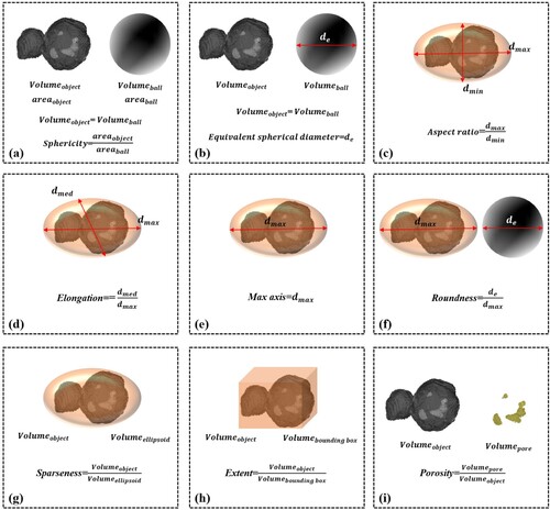
In various studies, a variety of parameters are employed to characterise the geometric attributes of powders and pores, including aspect ratio, porosity, sphericity, etc. [Citation10,Citation33] The majority of powder or pore characteristics can be determined, and the selected parameters are listed in :
Figure 4. The morphological parameters of the 3D geometrical object, the definition of (a) sphericity, (b) Equivalent sphericity diameter, (c) Aspect ratio, (d) Elongation, (e) Max axis, (f) Roundness, (g) Sparseness, (h) Extent, (i) Porosity.
Results and discussion
To investigate the impact of coaxial gas technology on powder morphology, numerical simulations of DPM were employed to analyze powder flow in the GA process and illustrate the influence of this technology on powder morphology. Additionally, to assess the effects of powder morphology on AM processes, powders utilised in DED and LPBF, as well as samples produced through these methods, were meticulously selected and characterised using SXCT technology. This technology enabled a thorough examination of powder morphology. Moreover, classification algorithms were utilised to categorise powder defects and identify the types of pores present in the AMed samples. Tensile tests were also conducted to evaluate the performance of the samples. The findings demonstrated that the integration of coaxial gas technology can enhance powder quality and improve the performance of the AMed samples.
The impacts of coaxial gas technology on powder morphology
All powders are produced by the GA equipment of our team, with or without coaxial gas technology, as depicted in (a). In addition to the high-speed gas flow used to break up the melt, the additional vertical gas flow is utilised to control vortex formation in the GA process, and the structure of the nozzle can be seen in (b). The GA process can be categorised into four stages based on the behaviour of the melt, as shown in (c): liquid shear, primary breakup, secondary breakup, and cooling and solidification [Citation27]. Each stage plays a crucial role in shaping the morphology of the powders. Particularly significant is the cooling and solidification stage, where the high-speed gas injected into the GA chamber can create vortexes outside the primary gas flow. These vortexes have the potential to drive smaller powders downstream, causing them to collide with larger powders in the atomization zone and resulting in powder defects.
Figure 5. (a) the GA nozzle with coaxial gas, (b) the schematic and for stages of the GA process.
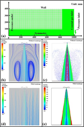
To investigate the impact of coaxial gas technology, numerical simulation using DPM is employed to simulate the gas flow and powder flow in the GA process. The geometry and boundary conditions are outlined in (a), while the technological parameters can be found in . Further details on the DPM setup can be found in the supplementary materials. The simulated results, depicted in (b–e), reveal that a vortex can form in the GA chamber in the absence of coaxial gas, as shown in (b). Numerous small-size powders follow the vortex, flowing backward into the atomisation zone, leading to collisions with droplets and the formation of satellite powders [Citation23], as illustrated in (c). Conversely, when coaxial gas is introduced into the GA process, as depicted in (d), the vortex is diminished, preventing powders from flowing into the breakup area and reducing the likelihood of collisions that produce satellite powders, as shown in (e).
Figure 6. (a) the geometry and boundary conditions of DPM, (b) the gas streamlines distribution GA process without coaxial gas, (c) the powder flow without coaxial gas, (d) the gas streamlines distribution GA process with coaxial gas, (e) the powder flow with coaxial gas.
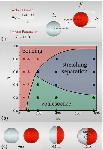
Moreover, in the GA process, the collision of powders can also result in the formation of hollow powders. Previous research has identified three distinct behaviours of droplets: bouncing, stretching separation, and coalescence, as illustrated in (b) [Citation37]. The collision behaviours of droplets can be characterised by a diagram involving two dimensionless parameters, the Weber number and impact parameter, with their definitions provided in (a). Studies have shown that coalescence during collisions can lead to the formation of bubbles within droplets, as depicted in (c). Therefore, the implementation of coaxial gas technology can effectively reduce the occurrence of satellite powders and hollow powders by eliminating the vortex and subsequently decreasing the probability of powder collisions.
Figure 7. (a) the definitions of Weber number and impact parameter, (b) the behaviors diagram of droplet collision, (c) the bubble formation in the coalescence process.
The qualification and classification of powder morphology
The powder samples are divided into four groups: non-optimal powders of DED, optimal powders of DED, non-optimal powders of LPBF, and optimal powders of LPBF. SXCT technology and 3D reconstruction technology were utilised to analyze the morphology of these powders, with four primary morphological parameters selected to characterise the features of powder morphology: equivalent spherical diameter (ESD), sphericity, aspect ratio, and porosity ratio.
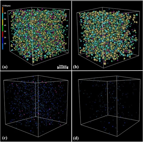
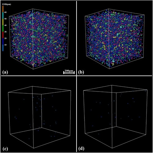
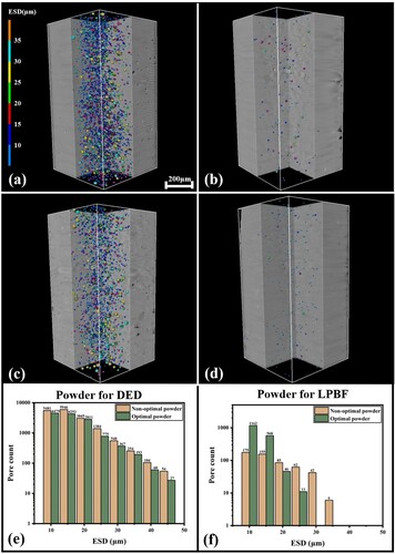
illustrates two types of powders for DED, displaying a particle size distribution (PSD) ranging from 50 μm to 70 μm. The inner pore distribution is also shown in (c) and (d), revealing a significant difference between the two powders in terms of pore distribution, with the non-optimal powders exhibiting larger and more numerous inner pores compared to the optimal powders.
Figure 8. (a) the 3D reconstruction of non-optimal powders of DED, (b) the 3D reconstruction of optimal powders of DED, (c) the pore distribution of non-optimal powders, (d) the pore distribution of optimal powders.
To comprehensively compare the powder morphology, the morphological parameters of DED powders are presented in . The ESD of the two powder types is nearly identical, as shown in (a) since they were sieved by the same machines, effectively eliminating the factor of PSD in the DED process. However, significant differences were observed in sphericity, aspect ratio, and porosity between the non-optimal and optimal powders, as illustrated in (b–d).
Figure 9. The morphological parameters of DEDed powders, (a) ESD, (b) Sphericity, (c) Aspect ratio, (d) Pore size.
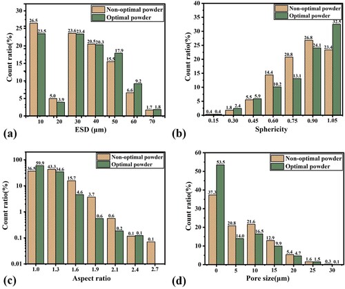
The non-optimal powders exhibit more irregular shapes, with a higher aspect ratio and lower sphericity, along with a porosity size distribution containing more and larger pores compared to the optimal powders, as depicted in (d). These findings indicate that the optimal powders demonstrate superior morphology and a lower porosity ratio.
Similarly, presents the two types of powders designed for LPBF, with a PSD ranging from 15 μm to 53 μm. The visualisation depicts the distribution of inner pores, highlighting a slight difference between the two powders. Due to the small size of the powders, it becomes challenging for bubbles to infiltrate, resulting in a porosity ratio of only 0.28% for optimal powders and 0.13% for non-optimal powders. This indicates that evaluating the morphology of these powder varieties is not a straightforward task.
Figure 10. (a) the 3D reconstruction of non-optimal powders of LPBF, (b) the 3D reconstruction of optimal powders of LPBF, (c) the pore distribution of non-optimal powders of LPBF, (d) the pore distribution of optimal powders of LPBF.
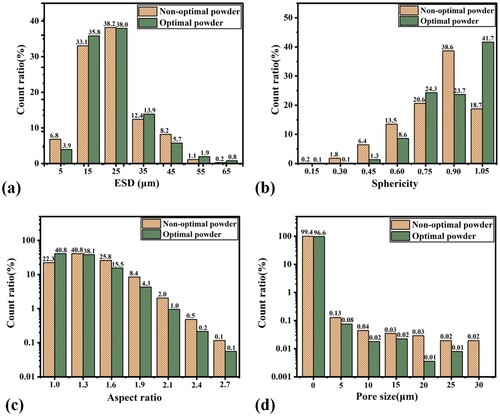
The morphological characteristics of LPBF powders are detailed in . The ESD and pore size distribution of the two powder types is also nearly identical, as depicted in (a) and (d). However, significant discrepancies are observed in sphericity and aspect ratio between the two powders, as shown in (b–c). The non-optimal powders exhibit more irregular shapes, with a higher aspect ratio and lower sphericity, indicating that the morphology of optimal powders is more uniform compared to non-optimal powders.
Figure 11. The morphological parameters of LPBFed powders, (a) the ESD of powders, (b) the sphericity of powders, (c) the aspect ratio of powders, (d) the pore size of powders.
Based on the characteristics of powder morphology, we have classified powder samples into four types: alien powders, satellite powders, normal powders, and hollow powders, as depicted in (a–d). By employing machine learning of the artificial neural network algorithms, more than 2000 powder samples are used to train the model, the input parameters are aspect ratio, sphericity, porosity, and ESD, and the output are the classifications of powders, as shown in (e). The accuracy of the model can reach 98.5%, as shown in (f). The classification algorithms and data for these powders have been uploaded to GitHub[Citation38]. For more detailed information, please refer to the instruction file of this project. The model was used to analyze the powder defect distribution of two types of powders, as shown in (g) and (h). For DEDed powders, the results indicate a substantial proportion of porosity powders, with the hollow powder ratio reaching 28.4% for optimal powders and 43.9% for non-optimal powders, suggesting that nearly half of the powders contain pores.
Figure 12. The morphology of (a) alien powders, (b) hollow powders, (c) normal powders, (d) satellite powders, (e) the structure of ANN, (f) the accuracy of ANN for powder classification, (g) the powder defect distribution of DEDed powder, (h) the powder defect distribution of LPBFed powder.
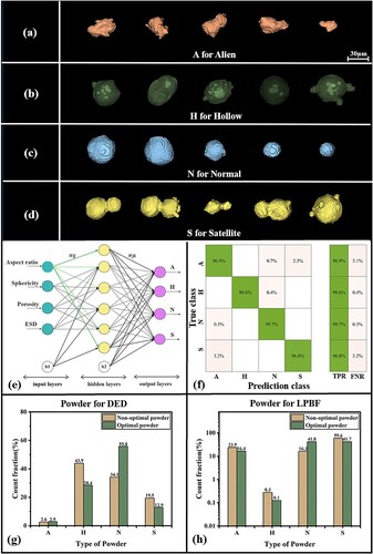
In the case of LPBFed powders, the defect distribution results reveal a significant proportion of satellite powders, with the porosity levels of both types nearly close to zero. The defect ratio for non-optimal powders is 83.7%, while for optimal powders it is 58.24%. The powder defect distribution diagram illustrates that the quality of optimal powders is quantitatively superior to that of non-optimal powders.
The impacts of the powder morphology on the distributions of pores and mechanical performance of the AMed samples
The powders mentioned above are utilised in AM technology, including DED and LPBF. The samples produced by DED and LPBF have been analysed using SXCT technology in our research. Each sample is chosen from the centre of the bulk manufactured by AM technology. The size of the SXCT zone of the AMed sample is set at 1mm × 1mm × 2 mm, and the pore distribution of each sample is listed in . (a) and (b) are manufactured using non-optimal powders, while (c) and (d) are manufactured using the optimal powders.
Figure 13. the pore distribution of (a) the DEDed sample of non-optimal powders, (b) the LPBFed sample of non-optimal powders, (c) the DEDed sample of optimal powders, (d) the LPBFed sample of optimal powders, (e) the pore size distribution of DEDed sample, (f) the pore size distribution of LPBFed sample.
When comparing the samples manufactured by DED and LPBF technology, the pore distribution diagrams reflect both the number and size of pores, with the samples manufactured by DED showing a higher pore count than those manufactured by LPBF, attributed to the powder buildup density and voids.
In the samples manufactured by DED technology, there are more pores in the non-optimal powder samples, with the number of pores of almost all sizes being greater than in the optimal powder samples, as shown in (e). As the pore size increases, the difference in numbers becomes more pronounced, indicating that porosity in the powders can lead to more pores in DED samples, and recent research has confirmed it.
On the other hand, the samples manufactured by LPBF technology exhibit numerous small-sized pores (below 10 μm) in the optimal powder samples, as shown in (f), almost ten times more than in the non-optimal powder samples. However, for larger-sized pores (over 30 μm), the samples manufactured using optimal powders have none of this size, while those manufactured using non-optimal powders have some large-sized pores. The porosity ratio of the two types of powders is nearly equal, but the key difference lies in the ratio of alien powders to satellite powders. Non-optimal powders contain more alien and satellite powders, with the alien powder increasing the gaps between the powders, while the smaller satellite powder can fill the voids, resulting in fewer small-sized pores in samples manufactured using non-optimal powders. Conversely, the uniform-sized normal powder has relatively larger buildup voids.
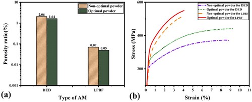
The porosity ratios of the AMed samples are calculated and shown in . The LPBFed samples exhibit a slight difference and are much lower than the DEDed samples, with only 0.07% and 0.05% porosity, respectively. The tensile curve indicates a slight difference of only 10 MPa in yield strength between the samples of the two types of GAed powders. The yield strength of non-optimal powder can reach 342 MPa with an elongation of 3.4%, while the yield strength of optimal powders can reach 352 MPa with an elongation of 4.1%.
Figure 14. (a) the porosity ratio of AMed samples, (b) the tensile curves of AMed samples.
Based on the powder morphology of the LPBF samples, the porosity of the two types of powder is almost equal. However, the non-optimal powder contains more satellite and alien particles, which decreases the performance of the LPBF samples. This can especially lead to the formation of larger pores in the samples, which is a main factor affecting the tensile strength of the samples.
The samples produced using DED with the two types of powder exhibit significant differences in performance. The tensile strength of the sample with optimal powder reaches 256 MPa, significantly lower than that of the LPBF sample, primarily due to the high porosity ratio, which can reach 1.64% – almost 30 times that of the LPBF samples. However, these samples demonstrate good elongation, reaching 9.3%. On the other hand, the tensile strength of the sample with non-optimal powder only reaches 220 MPa, much lower than the optimal powder sample, at only 86% of the optimal powder samples, due to the high porosity ratio, which can reach 2.06%.
These findings highlight the significant impact of coaxial gas technology on powder morphology and the performance of AMed components produced using these powders, particularly concerning powder defects. The presence of alien and satellite powder can influence the creation of voids between powders, leading to the emergence of GEP during the AM process. The porosity of the powder directly influences the formation of pores in the AM process. The results suggest that coaxial gas technology is effective in reducing powder defects and improving the performance of AMed components. However, there are still additional challenges that need to be addressed to enhance the quality of GAed powders.
The impacts of the powder morphology on the types of pores in AMed samples
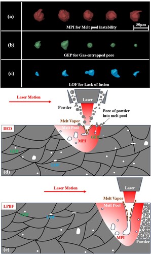
Based on previous research, it has been established that there are three distinct types of pores within the AM process, as evidenced by the morphology features depicted in (a–c). These pores are identified as the Melt pool instability pore (MPI), Gas-entrapped pore (GEP), and Lack of Fusion pore (LOF) [Citation39]. They are formed within the AM process through different mechanisms. Specifically, as illustrated in (d) and (e), MPIs result from the drag behaviour of the melt pool under the influence of a high-powered laser, GEPs are formed by the porosity within inner powders and the gaps among powders, and LOFs occur in gaps between powders that do not receive sufficient heat to melt the powder boundaries adequately. Understanding the characteristics and formation of these pores is crucial for comprehending the challenges associated with the AM process.
Figure 15. (a) the morphology features of MPI pores, (b) the morphology features of GEP pores, and (c) the morphology features of LOF pores. (d) the formation of GEP pores, LOF pores, and MPI pores in DED, (e) the formation of GEP pores, LOF pores, and MPI pores in LPBF.
The classification of the three types of pores relies on seven morphological parameters: max axis, roundness, sparseness, aspect ratio, sphericity, extent, and elongation. By analysing the distribution of different pore types in the Additive Manufacturing (AM) process, valuable insights can be gained. Previous research employed the decision tree algorithm for classification, enabling the determination of pore-type distribution, the threshold values of different types of pores are listed in (a) [Citation39]. The findings indicate that GEP is the most prevalent in the AM process, across both DED and LPBF, constituting over 60% of all AMed samples. This suggests that the presence of porosity in the powder and voids between powders are significant factors contributing to pore formation in the AM process [Citation40].
Figure 16. (a) the decision tree algorithm for pore classification, (b) the relationship between powder morphology and pore types, (c) the type of pore distribution in the DEDed sample, (d) the type of pore distribution in the LPBFed sample.
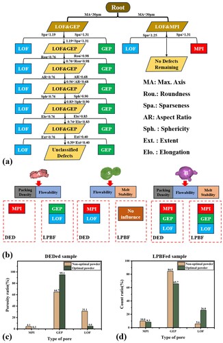
The diverse powder morphologies have specific impacts on pore formation, directly affecting packing density, flowability, and melt stability in the AM process, leading to the formation of different pore types as illustrated in (b). Alien powder can influence flowability, which in turn affects the stability of the powder feed rate in the DED process, potentially leading to MPI formation [Citation40]. Additionally, alien powder can impact packing density and contribute to void formation in the LPBF process, resulting in the occurrence of GEP and LOF in the LPBF process [Citation41]. Satellite powders can have an impact on the flowability and melt stability in the DED process, and these powders may not easily melt before reaching the melt pool, which can lead to issues such as LOF and MPI in the DED process [Citation42]. However, satellite powders typically do not have a significant effect on the LPBF process due to their good packing density. On the other hand, hollow powders play a significant role in pore formation in AM processes [Citation43, Citation44]. These powders can lead to the formation of all types of pores in the AM process and are the primary factor in pore formation in this AM process.
In DED technology, the larger size of powder particles presents a challenge in fully melting the solid powder, leading to a higher occurrence of LOF in samples manufactured using optimal powders. The ratio of samples manufactured with optimal powders is 26.1%, whereas for non-optimal powders, it is only 5.6%. On the other hand, porosity in powders is more easily melted in the DED process, resulting in more MPI pores with larger sizes. The abundance of laser power allows for the formation of large keyholes, with the ratio of samples manufactured with non-optimal and optimal powders being almost equal at 10.0% and 8.3%, respectively, as shown in (c).
In LPBF technology, the porosity ratio of the two types of powders is nearly equal and very low. Alien and satellite powders make up a significant portion of the non-optimal powder. Interestingly, the number of pores in LPBF samples using non-optimal powders is lower than those produced with optimal powders. The small satellite powders can fill the gaps between the powder, reducing the formation of small pores, as shown in (f). However, alien powders can create larger gaps between powders, leading to an increase in pore size in the LPBF process. Additionally, the tensile performance of the samples is affected by the presence of large-sized pores.
Conclusions
This study utilised SXCT and 3D reconstruction technologies to categorise and evaluate the morphology of powders and pores. By investigating two types of powders with varying defect ratios, the impact of powder morphology on AMed components becomes evident, allowing for the assessment of the influence of coaxial gas technology on powder morphology and AM component performance. The following conclusions are drawn below:
In GA technology, simulation results suggest that the integration of coaxial gas technology can enhance powder quality by eliminating vortex formation, thereby reducing the probability of collisions. This improvement in process control leads to a notable decrease in the ratios of satellite powders and hollow powders.
hollow powders are the predominant defects in GAed powders used in DED technology, as indicated by the pore morphology analysis. A significant portion of the pores are attributed to GEP, originating from the hollow powders. Since the DED process does not involve powder buildup, the primary factor contributing to suboptimal performance is the presence of hollow powders.
Alien and satellite powders are the major powder defects in LPBF technology, which can impact the formation of buildup voids and lead to the generation of large pores in components, thereby compromising the performance of LPBFed components. Analysis of pore morphology suggests that a substantial portion of the pores are GEP and LOF, caused by alien and satellite powders.
Supplemental Material
Download MS Word (513.2 KB)Acknowledgments
We thank the support of the Shanghai Synchrotron Radiation Facility for providing the beam time for the synchrotron X-ray CT work conducted on the BL16U2 and BL13HB beamlines.
Disclosure statement
No potential conflict of interest was reported by the author(s).
Data and code availability
Data availability The SXCT data are available under restricted access for having the large size in the order of TBs, which cannot be stored or transferred on commonly available data-sharing platforms, access can be obtained by request from the corresponding author. Analysis of results was performed by MATLAB with in-house developed codes, which can be accessed at links: https://github.com/Roshan-sjtu/powder-morphology-data.
Additional information
Funding
References
- Khorasani M, Gibson I, Ghasemi AH, et al. Laser subtractive and laser powder bed fusion of metals: review of process and production features. Rapid Prototyping J. 2023;29(5):935–958. doi:10.1108/RPJ-03-2021-0055
- Sun X, Chen M, Liu T, et al. Characterization, preparation, and reuse of metallic powders for laser powder bed fusion: a review. Int J Extreme Manuf. 2023;6(1).
- Rasiya G, Shukla A, Saran K. Additive manufacturing-a review. Mater Today Proc. 2021;47:6896–6901.
- Wallner S. Powder production technologies. BHM Berg- Huttenmann Monatsh. 2019;164(3):108–111.
- Mandal S, Sadeghianjahromi A, Wang C-C. Experimental and numerical investigations on molten metal atomization techniques – A critical review. Adv Powder Technol. 2022;33(11).
- Kassym K, Perveen A. Atomization processes of metal powders for 3D printing. Mater Today Proc. 2020;26:1727–1733.
- Wei M, Chen S, Sun M, et al. Atomization simulation and preparation of 24CrNiMoY alloy steel powder using VIGA technology at high gas pressure. Powder Technol. 2020;367:724–739. doi:10.1016/j.powtec.2020.04.030
- Aksoy A, Ünal R. Effects of gas pressure and protrusion length of melt delivery tube on powder size and powder morphology of nitrogen gas atomised tin powders. Powder Metall. 2006;49(4):349–354. doi:10.1179/174329006X89425
- Özbilen S, Ünal A, Sheppard T. Influence of superheat on particle shape and size of gas atomised copper powders. Powder Metall. 1991;34(1):53–61. doi:10.1179/pom.1991.34.1.53
- K. Zhou, C. Han, Metal Powder Based Additive Manufacturing, Weinheim: WILEY-VCH GmbH, 2023.
- Attar H, Prashanth KG, Zhang L-C, et al. Effect of powder particle shape on the properties of in situ Ti–TiB composite materials produced by selective laser melting. J Mater Sci Technol. 2015;31(10):1001–1005. doi:10.1016/j.jmst.2015.08.007
- Fu X, Huck D, Makein L, et al. Effect of particle shape and size on flow properties of lactose powders. Particuology. 2012;10(2):203–208. doi:10.1016/j.partic.2011.11.003
- Gao X, Abreu Faria G, Zhang W, et al. Numerical analysis of non-spherical particle effect on molten pool dynamics in laser-powder bed fusion additive manufacturing. Comput Mater Sci. 2020;179:109648.
- Dong Z, Han C, Zhao Y, et al. Role of heterogenous microstructure and deformation behavior in achieving superior strength-ductility synergy in zinc fabricated via laser powder bed fusion. Int J Extreme Manuf. 2024;6:045003.
- Liu Y, Sing SL. A review of advances in additive manufacturing and the integration of high-performance polymers, alloys, and their composites. Mat Sci Addit Manufact. 2023;2:1587.
- Rao, J, Sing SL, Lim, JCW, et al. Detection and characterisation of defects in directed energy deposited multi-material components using full waveform inversion and reverse time migration. Virtual Phys Prototyping. 2022;17(4):1047–1057.
- Savinov R, Wang Y, Shi J. An exploratory study on biocompatible Ti-6Mn-4Mo alloy manufactured by directed energy deposition. Mat Sci Addit Manufact. 2023;2(4). doi:10.36922/msam.2180
- Bidare P, Bitharas I, Ward RM, et al. Fluid and particle dynamics in laser powder bed fusion. Acta Mater. 2018;142:107–120. doi:10.1016/j.actamat.2017.09.051
- Chen Y, Clark S, Leung ACL, et al. Melt pool morphology in directed energy deposition additive manufacturing process. IOP Conf Ser Mater Sci Eng. 2020;861:012012.
- Chu F, Shen H, Liu J, et al. Improved ductility by reducing powder size in laser powder bed fusion of AlSi10Mg. Addit Manufact Front. 2024.
- Xue P, Zhu L, Xu P, et al. Effect of heat treatment on microstructure and mechanical properties of in-situ synthesized Ni2CrCoNb0.16 multi-principal element alloy manufactured by directed energy deposition. Mat Sci Eng A. 2023;862.
- Allimant A, Planche MP, Bailly Y, et al. Progress in gas atomization of liquid metals by means of a De Laval nozzle. Powder Technol. 2009;190(1-2):79–83. doi:10.1016/j.powtec.2008.04.071
- Beckers D, Ellendt N, Fritsching U, et al. Impact of process flow conditions on particle morphology in metal powder production via gas atomization. Adv Powder Technol. 2020;31(1):300–311. doi:10.1016/j.apt.2019.10.022
- Wu J, Xia M, Guo S, et al. Effect of electrode induction melting gas atomization process on fine powder yields: diameter of free-fall gas atomizer. J Mater Eng Perform. 2022;32:1–11.
- Luo S, Wang H, Gao Z, et al. Interaction between high-velocity gas and liquid in gas atomization revealed by a new coupled simulation model. Mater Des. 2021;212:1–12.
- Wu J, Xia M, Wang J, et al. Effect of electrode induction melting gas atomization on powder quality: satellite formation mechanism and pressure. Materials (Basel). 2023;16:2499.
- Luo S, Ouyang Y, Lai S, et al. 3D numerical modeling of gas atomization process for powder preparation based on similarity theory. Powder Technol. 2024;433:119244.
- Bartzsch G, Scherbring S, Richter J, et al. Gas atomization of Al-steels. Mater Today Commun. 2023;34:105388.
- Chen H, Chen Y, Liu Y, et al. Packing quality of powder layer during counter-rolling-type powder spreading process in additive manufacturing. Int J Mach Tools Manuf. 2020;153. doi:10.1016/j.ijmachtools.2020.103553
- Zhai W, Zhou W, Nai SML, et al. Characterization of nanoparticle mixed 316 L powder for additive manufacturing. J Mater Sci Technol. 2020;47:162–168. doi:10.1016/j.jmst.2020.02.019
- Chen H, Wei Q, Wen S, et al. Flow behavior of powder particles in layering process of selective laser melting: Numerical modeling and experimental verification based on discrete element method. Int J Mach Tools Manuf. 2017;123:146–159. doi:10.1016/j.ijmachtools.2017.08.004
- Chen G, Zhao SY, Tan P, et al. A comparative study of Ti-6Al-4V powders for additive manufacturing by gas atomization, plasma rotating electrode process and plasma atomization. Powder Technol. 2018;333:38–46. doi:10.1016/j.powtec.2018.04.013
- Ouyang Y, Luo S, Ren P, et al. Synchrotron X-ray computed tomography analysis of the morphological characterization of aluminum alloy powders produced by gas atomization. Powder Technol. 2023;429. doi:10.1016/j.powtec.2023.118904
- Richter J, Torrent CJJ, Krochmal M, et al. A comparative study using water atomized and gas atomized powder in laser powder bed fusion – Assessment of the fatigue performance. Int J Fatigue. 2023;168. doi:10.1016/j.ijfatigue.2022.107468
- Wang P, Zhou X-L, Li X-G, et al. Yu, Numerical and experimental investigation of close-coupled twin-nozzle gas atomization towards fine high-entropy alloy powder production. J Mater Process Technol. 2024;324:118238.
- Xiao YK, Bian ZY, Wu Y, et al. Effect of nano-TiB2 particles on the anisotropy in an AlSi10Mg alloy processed by selective laser melting. J Alloys Compd. 2019;798:644–655. doi:10.1016/j.jallcom.2019.05.279
- Chen X, Yang V. Bouncing, helical and buckling instabilities during droplet collision: newtonian and non-newtonian liquids. ArXiv. 2012. Accessed July 5, 2024. /abs/1210.3888.
- Luo S. Classification of powders. 2024. https://github.com/Roshan-sjtu/classification-of-powders.
- Poudel A, Yasin MS, Ye J, et al. Feature-based volumetric defect classification in metal additive manufacturing. Nat Commun. 2022;13(1):6369.
- Zhang K, Chen Y, Marussi S, et al. Pore evolution mechanisms during directed energy deposition additive manufacturing. Nat Commun. 2020;106(1):89–100. doi:10.3917/commu.106.0089
- Huang Y, Fleming TG, Clark SJ, et al. Keyhole fluctuation and pore formation mechanisms during laser powder bed fusion additive manufacturing. Nat Commun. 2022;13:1–11.
- Iebba M, Astarita A, Mistretta D, et al. Influence of Powder characteristics on formation of porosity in additive manufacturing of Ti-6Al-4V components. J Mater Eng Perform. 2017;26(8):4138–4147. doi:10.1007/s11665-017-2796-2
- Kenevisi MS, Lin F. Effect of powder characteristics on relative density and porosity formation during electron beam selective melting of Al2024 aluminum alloy. J Manuf Sci Eng. 2023;145(5). doi:10.1115/1.4056665
- Zhang Y, Lordan E, Dou K, et al. Influence of porosity characteristics on the variability in mechanical properties of high pressure die casting (HPDC) AlSi7MgMn alloys. J Manuf Processes. 2020;56:500–509. doi:10.1016/j.jmapro.2020.04.071