
 ?Mathematical formulae have been encoded as MathML and are displayed in this HTML version using MathJax in order to improve their display. Uncheck the box to turn MathJax off. This feature requires Javascript. Click on a formula to zoom.
ABSTRACT
A wire-based laser directed energy deposition process was developed to repair Q690D steel. The microstructure evolution, phase transformation and mechanical properties of the repaired specimens were investigated in detail. Excellent metallurgical bonding was achieved between the repaired zone and the substrate free of macroscopic defects. Typical columnar dendrites with grains grew perpendicularly from the fusion line to the deposition zone (DZ) centre. Microstructure in the DZ and heat-affected zone (HAZ) of the repaired specimen was predominated by lath martensite. The tensile properties of the repaired specimens were comparable to those of the substrate. The repaired specimens presented ∼200 MPa higher flexural strength than that of the substrates, while they have inferior ductility compared to the substrates under the three-point bend test. The average impact absorbed energy value for the repaired specimens achieved ∼85–90% of the substrates. This study introduces a novel restoration technique for offshore engineering platform maintenance.
1. Introduction
Due to the excellent strength-toughness combination and weldability, high strength low alloy (HSLA) steels have been widely applied in pressure vessel, linepipes, shipbuilding, bridge and automotive industries, as well as civil and offshore constructions [Citation1–3]. The application of HSLA steels for such components not only enables lighter and slender structures but also reduces construction costs without sacrificing structural integrity [Citation2,Citation4].
Q690D steel, a typical low-carbon bainite HSLA steel, presents excellent low-temperature toughness and weldability. This steel is usually manufactured through the thermomechanical controlled processing technique and can serve in a low-temperature environment. The Charpy impact toughness of the Q690D steel plate in the longitudinal direction shall not be lower than 47 J at −20 °C, according to theGB/T 1591-2018 standard [Citation5]. Q690D steel has been widely used in various fields, especially in the offshore engineering industry, such as leg racks and chords, pile legs of offshore engineering platforms, etc. [Citation6].
The service environment of offshore platforms has usually high-pressure, heavy load and high salt mist and alternate marine environments of wet and dry, causing serious wear and corrosion failures. In addition to the heavily corrosive environment, offshore platforms also frequently suffer severe impacts from sea wind, sea waves and dynamic working loads. The harsh service environment causes the frequent occurrence of pitting corrosion, cracks and wearing on the surface of the lifting rack for these pile legs of the offshore platforms, and these will then pose a severe threat to the overall safety of the whole structure. Therefore, routine repairing and maintenance are the key procedures to prolong the service life of the offshore platform and ensure its structure integrity.
As one of the traditional repairing techniques, the arc welding deposition technique has been widely applied in repairing marine engineering equipment in the dry dock. However, the effect of intrinsic high heat input induced by the arc welding deposition process results in large distortion, high residual stress and wide heat-affected zone (HAZ). In addition, the high heat input deposition process produces wide coarse grain HAZ which results in inferior toughness and strength of the deposited components [Citation7]. This can be mitigated with process control. Proper selection of the heat input during arc welding could be applied to control the microstructure evolution and the magnitude of residual stress [Citation8,Citation9].
Additive Manufacturing (AM) is a rapidly developing technique by which 3D components are fabricated by depositing layer by layer. AM demonstrates significant advantages in the manufacturing of metallic components regarding lead time and cost compared with traditional manufacturing techniques [Citation10]. Selective laser melting, as one of the AM processes, is a laser powder bed fusion (L-PBF) process which can produce metallic components with complex geometries. This technique has demonstrated the capacity to successfully print parts made out of many different alloys, including titanium alloys, nickel-based superalloys, aluminium alloys, stainless steels, tool steels, etc.[Citation11–13].
Laser-directed energy deposition (DED) is another AM process in which a feedstock material, normally blown powder or feeding wire, is deposited upon a substrate to build 3D components [Citation14]. Laser DED uses a high power density heat source to build the components, and it is typified by much lower heat input, less residual stress and distortion, minimal dilution, smaller HAZ, finer-grained microstructure and better mechanical properties [Citation15].
To the high flexibility and no restricted size of the enclosed shielding chamber, powder-based laser DED has attracted more attention on site-specific repairing, surface alloying and three-dimensional printing of complex shapes. Zhang et al. [Citation16] proposed a powder-based laser DED technology to repair a deteriorated steel bridge beam with material of A36 low-carbon steel. Oh et al. [Citation17] proposed a powder-based laser DED technology to repair 316L stainless steel. Zhu et al. [Citation18] reported repairing 12Cr12Mo stainless steel with powder-based laser DED technology. Sun et al. [Citation19–21] developed an underwater powder-based laser DED technology for on-site repairing of NV E690 steel, HSLA-100 steel and Ti–6Al–4V alloy. Good metallurgical bonding and acceptable mechanical properties were successfully achieved for the above repairing materials with the powder-based laser DED repairing technology.
According to the market-reported data, the unit wire material cost is nearly half of the powder material for Titanium, Tantalum, Inconel and other alloys [Citation22]. The unit cost can be up to 10 times lower than that of the powder, for instance, Fe-based shape memory alloy wire [Citation23,Citation24]. In addition, wire-based DED has a much higher material usage rate (up to 100%) compared with powder-based DED [Citation25–27]. As a solid feedstock material, wire-based DED does not expose operators to the hazardous powder environment. It should be noted, however, that fume emissions could be a risk from wire-based DED.
Nowadays, most of the investigations on wire-based DED are focused on wire and arc additive manufacturing (WAAM) [Citation23,Citation28,Citation29]. Significant emphasis for wire-based laser DED research work has been placed on the fabrication of 3D components and process control, such as forming accuracy and defect elimination [Citation30–32].
As a cost-competitive, high-quality, precision and effective AM technique, wire-based laser DED would be regarded as a promising solution for high-performance repair of damaged structural components to workable condition. Wen et al. [Citation33] reported a hot wire-based laser DED technique to repair precipitation hardening martensite stainless steel (PHMSS). Their study has revealed that the repaired PHMSS specimen achieved comparable or even superior mechanical properties than those of the substrate. Shrestha et al. [Citation34] investigated wire-based laser DED to repair Ti–6Al–4V alloy. Their results demonstrated that the developed wire-based laser DED repairing technology can achieve mechanical properties compared to the conventional Ti–6Al–4V alloy. Guo et al. [Citation35–37] reported the fabrication of Ti-6Al-4V alloy, 304 stainless steel and 5356 aluminium alloy with an underwater-wire based laser DED technique. Their investigated results demonstrated the in-situ emergency maintenance capability of wire-based laser DED technique for damaged critical structural components. In general, these recent findings have inspired the authors’ investigation of wire-based laser DED technique as a potential repairing technology for deteriorated offshore platforms.
To the best of the authors’ knowledge, few published works of literature have reported the use of the wire-based laser DED technique to repair the offshore structural components. In the present work, a wire-based laser DED technique was developed to repair pre-machined Q690D HSLA steel plates. The microstructural characteristics of the repaired Q690D HSLA steel in as-deposited condition were investigated in detail. The microhardness, tensile properties, Charpy impact toughness and bend performance of the repaired specimens in as-deposited condition were characterised to evaluate the mechanical properties of the repaired Q690D HSLA steel. The correlation between microstructure characteristics and mechanical properties of the repaired specimens was also analysed. Finally, the possibility of using wire-based laser DED technology to repair damaged Q690D HSLA steel components was evaluated.
2. Materials and experimental procedures
2.1. Materials
The material used in this study is a Q690D HSLA steel strip with a thickness of 30 mm. The Q690D HSLA steel has a minimum yield strength of 690 MPa. The chemical composition of the substrate (SU) is shown in . The carbon equivalent (CE) of the investigated material is calculated according to the following equation [Citation38]:
(1)
(1) which is recommended by the International Institute of Welding (IIW). All concentrations are defined in weight per cent. As seen in , the CE of Q690D HSLA steel is 0.40. Preheat is a frequently used approach to avoid cracks and minimise deflection and residual stresses of the AMed components. Considering the low carbon content as well as the economic costs, preheating was not carried out in this investigation. Optical micrograph and scanning electron microscope (SEM) images of the microstructure of the as-received substrate (SU) are shown in (a) and (b), respectively. The microstructure of the as-received substrate is a typical bainitic structure. The material of filler wire used in this study matches ER110S-G with a diameter of 1.2 mm. The chemical composition and mechanical properties of the filler wire as reported in the certificates are depicted in and , respectively. The CE of the filler wire is 0.58, as shown in .
Figure 1. Microstructure of the as-received substrate: (a) optical micrograph, (b) SEM micrograph.
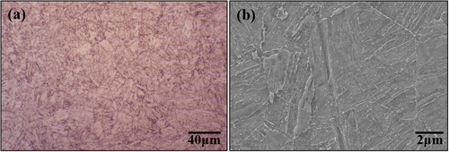
Table 1. Chemical composition of Q690D HSLA steel (wt%).
Table 2. Chemical composition of the ER110S-G filler wire (wt%).
Table 3. Mechanical properties of the ER110S-G filler wire.
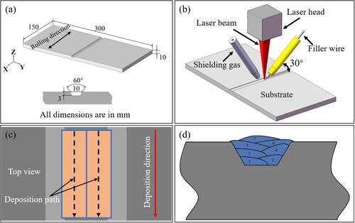
The as-received 30 mm-thick Q690D HSLA steel strip was sliced into three pieces of ∼10 mm-thick sheets by wire electric discharge machining (EDM) for deposition experiment and mechanical properties’ testing. The dimensions (length × width × thickness) of the substrate for this investigation were 300 mm × 150 mm × 10 mm. To simulate severe surface pitting corrosion, crack or wear damage of the in-serviced structure, trapezoidal grooves were made across the substrate via wire EDM. It is beneficial to obtain good fusion and smooth transition of deposited material along the sidewall without fusion or voids for a trapezoidal-filled cavity [Citation17,Citation39]. The dimensions of the substrate and the groove are shown in (a). The depth of the trapezoidal groove is designed for repairing surface damage with a depth of less than 3 mm in this scenario. The length of the repairing zone in this work is assumed to be the width of the substrate.
Figure 2. (a) Dimensions of Q690D HSLA substrate and the manufactured trapezoidal groove, (b) set-up for the wire-based laser directed energy deposition system, (c) deposition path (d) schematic of the deposition sequences for repairing.
2.2. Repairing process
Before the laser DED experiment, the vicinity of the trapezoidal groove in the substrate was ground with abrasive paper to clean the surface oxide. Acetone was used to clean the surface after grinding, and then the substrate was clamped on the work table to ensure adequate restraint.
A continuous wave fibre laser (n LIGHT corona CFX8000) equipment with a maximum output power of 8 kW was applied for the laser-DED experiments. The beam parameter product was 4.5 mm mrad. The wavelength of the laser was 1070 nm, which was delivered to the robotic welding cell through an optical fibre with a 100 μm core diameter. A laser welding head produced by Coherent was mounted on a 6-axis KUKA robot. An off-axis wire feeding nozzle was mounted on the laser welding head, which was used to deliver the filler wire to the molten pool. The laser head was set perpendicular to the substrate and the off-axis wire feeding nozzle was set at 30° relative to the substrate. A defocused laser beam was used to carry out the laser DED process to repair the Q690D HSLA steel, with a spot diameter of 3 mm at the beam/material interaction point. A schematic of the laser-DED set-up is shown in (b). The deposition process was carried out parallel to the rolling direction of the substrate. The front feed of the filler wire relative to the laser beam was chosen for all layers in this investigation. The schematics of the deposition path and deposition sequence to fill the machined trapezoidal groove are shown in (c) and (d), respectively. The top surface of the machined trapezoidal groove was shielded using pure argon gas to protect the molten pool during the deposition process. Argon gas was blown onto the top surface with a flow rate of 30 l/min.
In this study, a statistical design of experiments based on response surface methodology was employed to evaluate the effect of different deposition parameters on the deposition bead geometric shapes, dimensions and quality. A single-bead laser-DED process was carried out with varied deposition parameters (laser power, travelling speed and wire feed rate) to optimise the processing parameters. The details regarding the process parameters optimisation are shown in the supplementary document. The optimised processing parameters are listed in . Heat input for the wire-based laser-DED is calculated by the equation: heat input (J/mm) = efficiency × laser power (W)/travelling speed (mm/s). The efficiency considering the conduction heat loss only is about 80% [Citation40]. The calculated deposition rate is ∼0.9 kg/hr. A deposition length of 140 mm was adopted in seven layers to fill the trapezoidal groove successfully.
Table 4. Optimised laser-directed energy deposition parameters for repairing Q690D HSLA steel.
2.3. Metallography and hardness measurements
After fabrication, the as-repaired specimens were sectioned for metallographic analysis and micro-hardness evaluation by wire EDM. The specimens for metallographic and micro-hardness examination were subsequently ground and polished, followed by etching in a solution of 2% Nital for about 5 s. The macrostructure of the repaired specimen and the microstructure of the specimen were examined using an optical metallurgical microscope (KEYENCE VHX-1000C) and a ZEISS Gemini SEM 300 scanning electron microscope (SEM) and electron backscattered diffraction (EBSD). In addition, the microstructures and dislocations of the deposition zone (DZ) were observed by transmission electron microscopy (TEM, FEI Tecnai G2 F30). The samples for TEM analysis were sliced from the DZ. TEM samples were first ground to 50 μm in thickness and then the Ø3 mm punched discs were twin-jet electro-polished at −20 °C with a solution of 6% perchloric acid in methanol with a voltage of 40 V. Microhardness mapping profiles across the repaired zone were measured using a load of 500 g and a dwell period of 15 s with a HVS-1000Z Vickers micro-hardness tester. The nominal distance between indentations was 0.2 mm in the transverse direction, while in the through-thickness direction, the nominal distance between indentations was 0.4 mm across all regions.
2.4. Mechanical properties testing
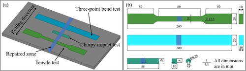
Tensile, three-point bend and Charpy impact tests were performed on both the as-received substrate and repaired specimens. Tensile, three-point bend and Charpy impact test specimens were manufactured following ASTM E8/E8M-2016a, ISO 5173:2023(E) and ASTM E23-02a standards, respectively. A face bend test was carried out to evaluate the bend properties and flexural strength of the repaired specimens. V-notch of the Charpy impact test samples was located in the centre of the repair zone to examine the impact toughness of the repaired samples. The Charpy impact tests were carried out at room temperature and −20 °C, respectively. Three replicates for tensile, three-point bend and Charpy impact testing were prepared to reduce experimental uncertainties. All the samples were extracted from both as-received substrate and repaired specimens using wire EDM, with the long axis of each specimen type being normal to the deposition direction, as shown in (a). Test coupons were sliced to coincide with the transverse direction of the material, and the dimensions and configurations for each type are described in (b). The deposited reinforcements in the face regions were milled to make sure the tensile, three-point bend and Charpy impact test samples of the repaired specimens were as flat as the samples from the substrate.
Figure 3. (a) Extracted location of the mechanical properties test specimens, (b) Dimensions and configurations of specimens for mechanical property testing.
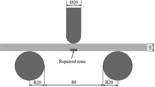
Uniaxial tensile and three-point bend tests were conducted in a Shimadzu AG-IC electronic universal test machine with a maximum load of 100 kN at room temperature. The diameter of the former, the support roller diameter and the support span (distance between the rollers) for the three-point bend test are shown in . The Charpy V-notch impact tests were carried out on an MST model ZBC2752-D impact test machine at room temperature and −20 °C, respectively. Following the tensile and Charpy impact tests, the fractured surface morphologies of all the specimens were characterised using ZEISS GeminiSEM 300 SEM installed with an Energy Dispersive X-ray Detector (EDX).
Figure 4. Schematic diagram of the three-point bend test setup, all dimensions are in mm.
3. Results and discussion
3.1. Macrostructure
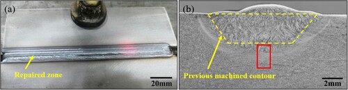
The macrostructure of the repaired Q690D HSLA steel specimen is shown in . It can be seen that the pre-machined trapezoidal-shaped groove was successfully repaired by the wire-based laser-DED technique. The surface profile of the repaired specimen is illustrated in (a), which suggests a good surface appearance without spatters on the substrate. The repaired zone and the substrate demonstrate an excellent metallurgical bonding and the repaired specimen showed fully dense structures with no porosity, crack or lack of fusion defects, as seen in (b). In the as-deposited condition, the depth of penetration was ∼0.5 mm, and the height of reinforcement was ∼1 mm. HAZ appears to be pronounced in the vicinity of the repaired zone with a width of around 1 mm. A very low dilution rate was achieved for the repaired specimen due to the application of the conduction mode deposition process under a defocused laser beam. The repaired zone can be divided into two distinct metallurgical regions, namely the deposition zone (DZ) and the heat-affected zone (HAZ). Furthermore, with an increase in the distance to the fusion line HAZ suffered from different thermal cycles, especially different peak temperatures. The HAZ can be subdivided into the intercritical HAZ (ICHAZ), the fine-grained HAZ (FGHAZ) and the coarse-grained HAZ (CGHAZ) which is adjacent to the fusion zone itself.
Figure 5. (a) Surface profile of wire-based laser DED-repaired specimen, (b) macroscopic cross-section profile of the repaired specimen.
3.2. Microstructure
The DZ comprises columnar dendrites with grains grown perpendicularly from the fusion line to the molten pool centre, as shown in . The columnar grains grew complied with the direction of the fastest heat dissipation. The SEM morphologies of the DZ and sub-HAZ microstructures are shown in . Lath martensite (LM) is predominated in both the top and bottom regions of the DZ and the prior-austenite grain shows a large grain structure, as presented in (a) and (b), respectively. Meanwhile, some amount of tempered martensite (TM) was found in the bottom region of the DZ, as seen in (b). In the repairing process, the filler wire was melted by the laser and deposited layer by layer into the pre-machined groove. During the following cooling process, the liquid material was transformed into columnar grains along the maximum heat flow direction at the solidification front when the temperature was below Ar4 [Citation19]. In the solidification process, amounts of very large austenite grains formed. As a high-power density processing technique, the laser DED process has a very low heat input (0.5 kJ/mm in this investigation) and a very high-temperature gradient. The cooling rate of laser DED is usually as high as 103–105 °C/s [Citation41,Citation42]. At this rapid cooling rate, the transformation of ferrite from austenite in the DZ was suppressed, causing the formation of martensite from the austenite lattice. The austenite transformed into LM based on the Kurdjumov-Sachs (K-S) orientation relationship when the temperature drops down to the martensite start temperature (Ms) [Citation43]. The layer-by-layer deposition process induces an interlayer heat treatment in the DZ, which is introduced from the subsequent deposition layer to the prior deposited layer. The deposited material, except for the last deposition layer, also experienced multiple thermal cycles during the multi-layer repairing process [Citation44]. The microstructure on the top region of the DZ predominated elongated LM within a large columnar grain structure, as shown in (a). As the bottom region of the DZ suffered from repeated cyclic re-heating and re-cooling treatment, the generated LM in this region was partially tempered. The bottom region of the DZ comprises columnar dendrites and the columnar grain microstructure presents LM mixed with TM, as shown in (b).
Figure 6. SEM micrographs showing the microstructures in the different sub-zones of the repaired specimen (a) the top region of DZ, (b) the bottom region of DZ, (c) CGHAZ, (d) FGHAZ, (e) ICHAZ, (prior austenite grain boundaries are signified with arrows).
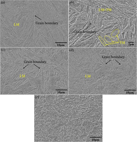
The microstructure of the HAZ around the trapezoidal-shaped fusion line (in (b)) was further investigated under SEM. No obvious difference was identified between the microstructure in the horizontal and vertical directions of HAZ. The microstructure of the sub-HAZs extracted from the red box in (b) is presented in (c), (d) and (e), respectively. The microstructures of CGHAZ and FGHAZ are predominantly LM with reduced gradually grain size from the CGHAZ to the FGHAZ. Whilst the microstructure in ICHAZ shows extremely different features, which is a mixture of martensite and retained bainite.
During the repairing process, substrate material surrounding the trapezoidal-shaped fusion line was heated to exceed the phase transformation temperature, Ac1, causing the material in the HAZ to experience solid-state phase transformation. The microstructural evolution in each sub-HAZ is primarily dominated by the experienced peak temperature and the cooling rate [Citation38]. The peak temperature of the HAZ gradually decreased as the distance from the fusion line. In the CGHAZ (adjacent to the fusion line), the peak temperature was raised to 1300 °C or even higher (but still lower than the melting point) for a sufficient duration to ensure full re-austenization, as well as rapid grain growth [Citation40]. With increasing distance from the fusion line, the peak temperature in the FGHAZ was slightly higher than the Ac3 temperature, and it still ensured the occurrence of completed re-austenization. However, austenite grain growth was limited due to the relatively low peak temperature and a short period at the temperature in the FGHAZ [Citation45]. When the distance to the fusion line increased further, the peak temperature experienced in the ICHAZ was between the Ac1 and Ac3 temperatures. The substrate material in this sub-zone partially transformed into austenite. The transformed austenite in the CGHAZ, FGHAZ and ICHAZ was quenched due to the rapid cooling rate in the wire-based laser DED process. LM was formed in these sub-HAZs. The grain size varied gradually from the CGHAZ to the FGHAZ because of the gradually reduced peak temperature. With smooth sub-zone transitions, no obvious boundary between the CGHAZ and FGHAZ was identified. The microstructure in the HAZ shows distinct differences compared with the CGHA and FGHAZ. In the ICHAZ, the partially transformed austenite was quenched into martensite, while the un-transformed bainite was retained, as seen in (e). The martensite within the ICHAZ reflects the island-shaped morphology with different sizes.
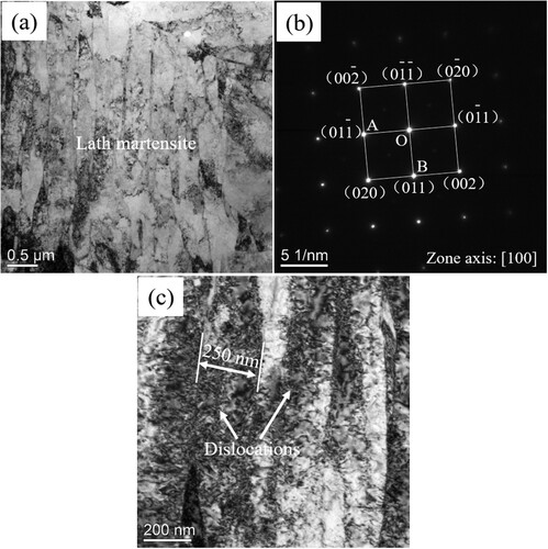
shows the bright field TEM micrographs of the specimen extracted from the top region of the DZ under the crystallographic zone axis <100>. The LM morphology can be identified in the TEM image ((a)). A body-centred cubic lattice structure can be confirmed according to the selected area electron diffraction (SAED) pattern ((b)). The width of the martensite lath is approximately 250 nm, as depicted in (c). A notable feature is that there are a large number of dislocation structures such as dislocation tangles distributed in the laths ((c)), which coincides with the accelerated cooling rate, contributing to the high strength of the repaired zone.
Figure 7. Bright filed TEM images of the microstructure of (a) the top region of the deposition zone, (b) the corresponding SAED pattern and (c) dislocation distribution.
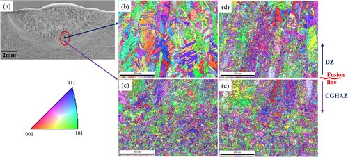
To examine potential variation or difference in the crystallographic texture of the repaired specimen at as-deposited condition, EBSD characterisation was carried out in the vicinity of the bottom fusion line, as depicted in (a). The inverse pole figures of the DZ and CGHAZ in the vicinity of the bottom fusion line as-deposited condition are presented in (b) and (c) respectively. To understand the potential change in crystallographic texture and grain boundary behaviour of the repaired interface after the tensile test, EBSD analysis was carried out on the repaired specimen after the tensile test. The details of the tensile test will be discussed in Section 3.4. The inverse pole figures of the DZ and CGHAZ in the vicinity of the bottom fusion line after the tensile test are demonstrated in (d) and (e), respectively. demonstrates a tremendous difference in the grain morphologies. The microstructure of the DZ and CGHAZ in the vicinity of the bottom fusion line does not seem to present any dominant crystallographic orientation. The DZ above the bottom fusion line presents very large columnar grains, which are perpendicular to the fusion line. This is because the columnar dendrite in this sub-zone grew perpendicularly from the fusion line to the deposition centre and complied with the direction of the fastest heat dissipation. However, the CGHAZ below the bottom fusion line exhibits a polygonal morphology and fine grain size. After the tensile test, a large amount of sub-grains were formed inner the previous grains in the DZ and CGHAZ, as demonstrated in (d) and (e), which is particularly prominent inner the previous large columnar grains in the DZ ((e)). This is because plastic deformation at large strain-induced under the tensile test pumped up dislocation density and correspondingly grain refinement with numerous sub-grain and grain boundary formations [Citation46–48].
Figure 8. Inverse pole figure of specimens as-deposited condition and after the tensile test: (a) cross-section of the repaired specimen, (b) as-deposited DZ above the fusion line, (c) as-deposited CGHAZ below the fusion line, (d) DZ above the fusion line after the tensile test, (e) CGHAZ below the fusion line after the tensile test.
Additionally, the corresponding distributions of grain boundary misorientation are presented in . The coexistence of low-angle grain boundaries (LAGBs, <15°) and high-angle grain boundaries (HAGBs, ≥15°) in the microstructure was identified, as presented in . The grain boundary distribution as a function of misorientation is shown in (e). The LAGBs comprise 54% of all boundaries in the as-deposited DZ above the bottom fusion line. The formation of LAGBs in this sub-zone can be attributed to the rapid solidification of the melted filler material and the following fast solid-state phase transformation during the wire-based laser DED repairing process [Citation49,Citation50]. However, the proportion of LAGBs in the as-deposited CGHAZ below the bottom fusion line is decreased to 35%, which is much lower than that in the DZ above the bottom fusion line, as shown in (e). This is probably because the heat accumulation in the CGHAZ by the multiple thermal cycles during the multi-layer repairing process results in the movement and annihilation of LAGBs [Citation49,Citation51].
Figure 9. Grain boundary misorientation maps of the DZ and CGHAZ in the vicinity of the bottom fusion line as-deposited and after the tensile test, (a) as-deposited DZ above the fusion line, (b) as-deposited CGHAZ below the fusion line, (c) DZ above the fusion line after the tensile test, (d) CGHAZ below the fusion line after the tensile test, (e) misorientation angle distributions.
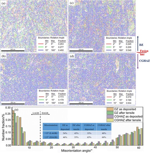
After the tensile test, the fraction of LAGBs in the DZ drops down to 45%, while it slightly increases to 40% in the CGHAZ, as seen in (e). The evolution of LAGB’s fraction is closely related to the motion of dislocations. Because the intense work hardening under high strain during the tensile test leads to an increased number of substructures, and thus the fraction of LAGBs increases with the increasing strain [Citation52]. The repairing process results in inhomogeneous microstructure and mechanical properties in the repaired specimens. The DZ is strengthened compared with CGHAZ and substrate. This will be further discussed in the following Sections. The sub-zones of the repaired specimen may suffer from different strain rates under tensile test (e.g. the DZ suffered from a low strain rate and the CGHAZ suffered from a high strain rate). Under a low strain rate, a relatively large fraction of the HAGBs is obtained. This is due to the sufficient time to accomplish the transition of dislocations → LAGBs → HAGBs [Citation53], which causes the drops of the fraction of the LAGBs in the DZ after the tensile test. However, short reaction time under a high strain rate leads to an incomplete process of LAGBs → HAGBs, resulting in an increase in the fraction of the LAGBs in the CGHAZ after the tensile test [Citation53].
3.3. Microhardness
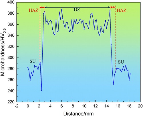
The multi-layer deposition strategy results in a heterogeneous structure in the repaired zone. The microhardness mapping of the repaired specimen is shown in . The DZ, HAZ and SU can be distinguished clearly from the hardness contour map due to the hardness variation in different zones. The average microhardness of the substrate is ∼275 HV0.5. The upper region of the DZ shows a maximum hardness of ∼370 HV0.5. This can be attributed to the hardened martensite and high dislocation density resulting from the rapid cooling rate [Citation19]. Tempering occurred due to the multiple re-heating caused by the subsequent overlapping tracks and hence significant tempering of the martensite occurs in the bottom region of the DZ. The hardness at the bottom region of the DZ is relatively lower than that of the upper region of the DZ with a value of ∼320 HV0.5. illustrates the microhardness profile extracted across the repaired zone at 1 mm below the top surface, as seen in the black dot line in . The peak hardness is identified in the un-tempered DZ and CGHAZ with a value of ∼380 HV0.5. The hardness dramatically drops from the CGHAZ towards the ICHAZ. The lowest hardness is located in a narrow soft ICHAZ (∼0.2 mm) with a value of ∼240 HV0.5, which is ∼35 HV0.5 lower than the substrate. Narrow hardness ‘valleys’ are seen in the ICHAZ adjacent to the substrate. Rapid heating and cooling rates associated with the wire-based laser DED process lead to the full generation of martensite in the DZ, CGHAZ and FGHAZ, and the partial transformation of martensite in the ICHAZ. The varied peak temperatures and thermal cycles endured in this narrow transition region caused a rapid hardness decrease from CGHAZ to ICHAZ. The ICHAZ suffered high-temperature tempering during the repairing process, which may result in a reduction in the dislocation density and development of a narrow soft region [Citation40]. This soft ICHAZ surrounding the repaired zone would be the weakest region for the repaired specimen.
Figure 10. Microhardness mapping of the repaired specimen.
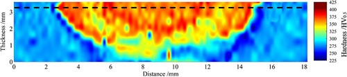
Figure 11. Extracted hardness profile across the repaired zone.
3.4. Tensile properties
The representative engineering stress-strain curves for the substrate (SU) and repaired specimens (RP) are illustrated in . The details of the transverse tensile test results are summarised in . The yield strength (YS), ultimate tensile strength (UTS) and elongation for the repaired specimens were 780, 809 MPa and 16.7%, respectively. They were very close to those of the substrate which had a YS of 781 MPa, UTS of 810 MPa and an elongation of 17.7%, respectively. The fractured samples after the tensile test are shown in . All repaired specimens failed in the substrate well away from the repaired zone, as shown in (b). The repaired specimens demonstrate almost the same tensile properties as the substrate even though the wire-based laser DED process results in a narrow soft ICHAZ. This result indicates that the repairing process did not deteriorate the tensile properties of the Q690D HSLA steel. Chen et al. [Citation19] carried out a powder-based laser DED technique to repair the NV E690 steel. The YS, UTS and elongation of their repaired specimens achieved 96%, 96% and 65% of those of the NV E690 steel substrate, respectively. The repaired specimens failed in the centre of the repaired zone after the tensile test [Citation19]. As can be seen from , wire-based laser DED technique repaired specimens in this work achieved better tensile properties, and all the specimens failed in the substrates well away from the repaired zone.
Figure 12. Engineering stress-strain curves of the tensile test for the substrates and repaired specimens.
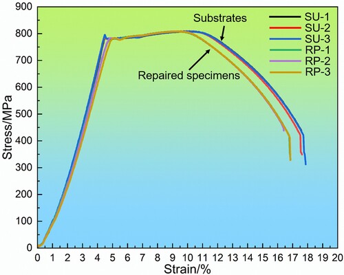
Figure 13. Fracture location of the tensile test specimens, (a) substrates and (b) repaired specimens.
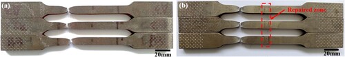
Table 5. Tensile properties for the substrates and the repaired specimens.
It is well-recognised that hardness is generally an indicator of material strength [Citation54]. An increase in hardness would increase the strength of the material [Citation55]. Thus, it can be deduced from the hardness mapping results of the repaired specimen in that the DZ and HAZ (except the surrounding ICHAZ) were strengthened by the wire-based laser DED repairing process. In this case, the strengthened DZ and HAZ (except the surrounding ICHAZ) can, therefore, act as a strong constraint on plastic deformation in the adjacent narrow soft ICHAZ (∼0.2 mm), and this caused the majority of tensile plastic deformation accumulated in the substrate and subsequent fractured out of the soft ICHAZ [Citation56,Citation57]. Similar findings were reported by Lee et al. [Citation56] in the tensile test of the laser welded DP780 high-strength steel.
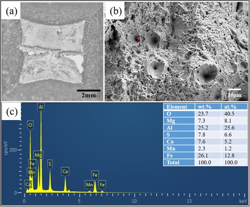
To investigate the fracture mechanisms, fracture morphologies of both the substrates and repaired specimens were examined under optical microscope and SEM. Since all repaired specimens fractured in the substrate well away from the repaired zone, both the substrates and repaired specimens show the same fracture morphologies. Therefore, only representative fracture surfaces of these failed specimens are presented in . In (a), it can be seen that the specimen was split into two segments with the boundary between the segments coinciding with the mid-thickness position within the plate. Similar phenomena were also found in the authors’ previous work [Citation38,Citation40]. This splitting can be attributed to the specific rolling process for the substrate, which can lead to variation in the chemical composition in the through-thickness direction. (b) shows the fractured surface of the specimen under high magnification. It reveals that the fracture surface is composed of predominately of large voids and deep equiaxed dimples, which demonstrates the ductile fracture behaviour. The macro- and micro-morphology of the fracture surfaces reveal that substrates and repaired specimens have good ductility. There are several small spherically-shaped inclusion particles distributed inside the large ductile dimples. The EDX spectrum indicates that the inclusion particles are rich in O, Mg, Al, S, Ca, Mn and Fe, as shown in (c).
Figure 14. Fracture surface morphology for the tensile test specimens, and the results of EDX analysis: (a) macro fracture surface, (b) high magnification fracture surface, (c) EDX spectrum for the inclusion particles.
3.5. Bend properties
A three-point bend test was carried out on the face side of the repaired specimens as well as substrate samples to evaluate the bend properties and flexural strength. The flexural strength σ of the material under the three-point bend test can be calculated by the following equation [Citation58]:
(2)
(2) where F is the loading force at the span centre. L, b and h represent the support span, width and thickness of the test specimen, respectively. The flexural strain of the outer edge ϵ can be calculated by the following equation [Citation58]:
(3)
(3) where d is the displacement of the span centre. Engineering stress-strain curves of substrates and repaired specimens during the three-point bend test are shown in . Test results for substrates (SU) and repaired specimens (RP) are displayed in . The average flexural strength for the repaired specimens is ∼1680.7 MPa, which is approximately 200 MPa higher than that of the substrates. All repaired specimens have cracked from the fusion line, while no cracks were observed at substrates, as seen in . The substrates demonstrated good ductility under the three-point bend test. Compared to substrates, the repaired specimens present higher flexural strength but inferior ductility. This can be attributed to the generation of martensite in the DZ and HAZ, which strengthened the repaired zone but reduced its ductility.
Figure 15. Engineering stress-strain curves of three-point bend test for the substrates and repaired specimens.
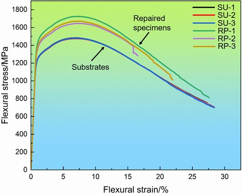
Figure 16. Three-point bend tested specimens, (a) top view of substrates, (b) side view of substrates, (c) top view of repaired specimens, (d) side view of repaired specimens.
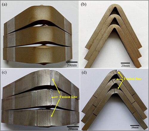
Table 6. Results of the three-point bend test for substrates and repaired specimens.
3.6. Charpy impact properties
The Charpy V-notch impact toughness results for substrates and repaired specimens at room temperature and −20 °C are presented in and , respectively. The average impact absorbed energy at room temperature is ∼234 J for the substrates and ∼210 J for the repaired specimens. The latter achieves ∼90% of the substrate, as demonstrated in (a). The average impact absorbed energy at −20 °C for the substrates is ∼233 J and ∼197 J for the repaired specimens, which achieves ∼85% of the substrate, as demonstrated in (a). The absorbed energies for the substrate keep constant with the test temperature increased from −20 °C to room temperature. Additionally, the absorbed energies for the repaired specimens increased by ∼5% with the test temperature increased from −20 °C to room temperature. According to the ISO 16834:2012 standard [Citation59], the demand impact absorbed energy value for the welded joint is no less than 27 J, as indicated by the blue dashed line in and (a). In this study, all impact-absorbed energy values of the repaired specimens are far above the required impact-absorbed energy value of 27 J. This demonstrates the repairing of Q690D HSLA steel via wire-based laser DED can meet the industrial standard and provide sufficient impact toughness at low temperatures. Chen et al.’s work [Citation19] showing the average impact absorbed energy at −40 °C for the powder-based laser DED-repaired NV E690 steel specimens achieved 68% of that of the substrate with a value of 47 J, which surpassed the industrial standard for the toughness of the weld joint (27 J, according to ISO 16834:2012 [Citation59]). In our study, wire-based laser DED technique repaired specimens achieved better Charpy impact toughness, which was ∼85–90% of the substrates.
Figure 17. Charpy impact test results tested at room temperature, (a) impact absorbed energy of the substrates and repaired specimens, (b) macro-fractured surface of the substrate, (c) macro fractured surface of the repaired specimen, (d) high magnification fracture surface of the substrate, (e) high magnification fracture surface of repaired specimen extracted from the substrate region, (f) high magnification fracture surface of repaired specimen extracted from the repaired zone.
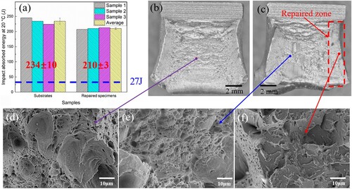
Figure 18. Charpy impact test results tested at −20 °C, (a) impact absorbed energy of the substrates and repaired specimens, (b) macro-fractured surface of the substrate, (c) macro-fractured surface of the repaired specimen, (d) high magnification fracture surface of the substrate, (e) high magnification fracture surface of repaired specimen extracted from the substrate region, (f) high magnification fracture surface of repaired specimen extracted from the repaired zone.
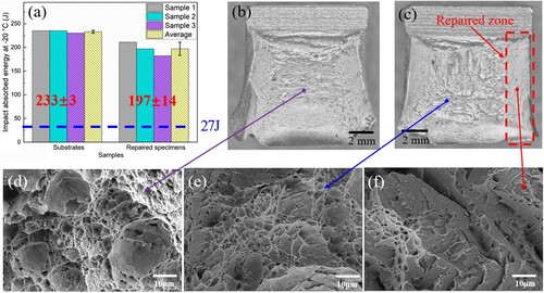
(b) and (c) and (b) and (c) present the macroscopic fracture surfaces of the selected substrate and repaired specimen after the Charpy impact test at room temperature and −20 °C, respectively. It can be seen that the fractured surface presents a dark surface, as hown in (b) and (b). Large voids and deep equiaxed dimples can be observed from the SEM photomicrograph, as shown in (d) and (d). It again validates the ductile fracture behaviour of the substrate under impact test. For the repaired specimen, the fractured surface can be denoted as the substrate zone and the repaired zone, as shown in (c) and (c). The substrate zone presents as a dark surface, suggesting a ductile fracture. The substrate zone in (e) and (e) shows a typical ductile fracture characteristic with a great number of dimples and microvoids. The repaired zone shows a brittle surface featuring brightness and high planeness, as seen in (c) and (c). The brittle region of the fracture surface revealed a cleavage-dominated fracture with a small proportion of ductile dimples, as seen in (f) and (f). It indicates the repaired specimen features a combination of brittle and slight ductile characteristics. The slight deterioration of the Charpy impact properties for the repaired specimens can be ascribed to the hardening of the repaired zone. Rapid cooling process during wire-based laser DED repairing process causes the generation of hardened martensite in the FZ and HAZ, which strengthens the repaired zone but also increases its brittleness.
4. Conclusions
From this investigation the following conclusions were derived:
Wire-based laser DED was successfully applied to repair Q690D HSLA steel. A high-performance and defect-free repair zone was achieved by this repairing technique.
Microstructure in the DZ and HAZ of the repaired specimen was dominated by LM. The majority of DZ was featured by large grain size columnar grains. and the grain size reduced gradually from the CGHAZ to ICHAZ.
The hardness distribution of the repaired specimen was non-uniform. The maximum hardness was located in the untempered DZ and CGHAZ with a value of ∼380 HV0.5. Then the hardness dramatically dropped from the CGHAZ towards the ICHAZ. There were very narrow hardness ‘valleys’ (∼0.2 mm) located in the ICHAZ, where the hardness locally dropped below that for the substrate.
The tensile properties of repaired specimens were comparable to that of the substrate, with all repaired specimens failing in the substrate far away from the repaired zone. Compared to substrates, the repaired specimens demonstrated higher flexural strength but inferior ductility under the three-point bend test.
The formation of martensite in the FZ and HAZ led to increased hardness and strength in the repaired zone and also a reduction in the impact toughness at room temperature and −20 °C. However, the repaired specimens via wire-based laser DED technique are still able to provide sufficient impact toughness at low temperatures and meet the industrial standard.
Author contributions
Wei Guo: Supervision, Conceptualisation, Writing-original draft and Funding acquisition. Libo Wang: Investigation and Visualisation. Lei Su: Methodology. Xiuquan Ma: Supervision and Conceptualisation. Jian Wang: Supervision, Conceptualisation and Funding acquisition. Shengwei Hou: Investigation. Binyan He: Writing-review and editing.
Supplemental Material
Download MS Word (1.3 MB)Acknowledgements
The authors are grateful for laser-directed energy deposition experiment support from Mr Xiuhui Yan. The authors would like to express deep gratitude to the Analytical & Testing Center of Huazhong University of Science and Technology for providing the materials characterisation facilities.
Disclosure statement
No potential conflict of interest was reported by the author(s).
Data availability statement
The data will be made available upon request.
Additional information
Funding
References
- Yan JB, Yang X, Luo Y, et al. Axial compression behaviours of ultra-high performance concrete-filled Q690 high-strength steel tubes at low temperatures. Thin Wall Struct. 2021;169(108419):1–20. doi:10.1016/j.tws.2021.108419
- Cadoni E, Briccola D, Dotta M, et al. Combined effect of elevated temperature and high strain rates on S690QL high strength steel. J Constr Steel Res. 2022;199(107519):1–13. doi:10.1016/j.jcsr.2022.107519
- Tong L, Niu L, Ren Z, et al. Experimental investigation on fatigue behavior of butt-welded high-strength steel plates. Thin Wall Struct. 2021;165(107956):1–11. doi:10.1016/j.tws.2021.107956
- Schroepfer D, Kannengiesser T. Correlating welding reaction stresses and weld process conditions for high-strength steel S960QL. Weld World. 2014;58:423–432. doi:10.1007/s40194-014-0127-x
- Huang X, Ge J, Zhao J, et al. A continuous damage model of Q690D steel considering the influence of Lode parameter and its application. Constr Build Mater. 2020;262(120067):1–16. doi:10.1016/j.conbuildmat.2020.120067
- Guo H, Lei T, Yu J, et al. Experimental study on mechanical properties of Q690 high strength steel in marine corrosive environment. Int J Steel Struct. 2021;21(2):717–730. doi:10.1007/s13296-021-00468-z
- Saboori A, Aversa A, Marchese G, et al. Application of directed energy deposition-based additive manufacturing in repair. Appl Sci. 2019;3316(9):1–26. doi:10.3390/app9163316
- Lopes J, Agrawal P, Shen J, et al. Evolution of microstructure and mechanical properties in gas tungsten arc welded dual-phase Fe50Mn30Co10Cr10 high entropy alloy. Mater Sci Eng A. 2023;878(145233):1–15. doi:10.1016/j.msea.2023.145233
- Shen J, Agrawal P, Rodrigues T, et al. Microstructure evolution and mechanical properties in a gas tungsten arc welded Fe42Mn28Co10Cr15Si5 metastable high entropy alloy. Mater Sci Eng A. 2023;867(144722):1–13. doi:10.1016/j.msea.2023.144722
- Deirmina F, AlMangour B, Grzesiak D, et al. H13–partially stabilized zirconia nanocomposites fabricated by high-energy mechanical milling and selective laser melting. Mater Des. 2018;146:286–297. doi:10.1016/j.matdes.2018.03.017
- Seede R, Shoukr D, Zhang B, et al. An ultra-high strength martensitic steel fabricated using selective laser melting additive manufacturing: densification, microstructure, and mechanical properties. Acta Mater. 2020;186:199–214. doi:10.1016/j.actamat.2019.12.037
- Deirmina F, Peghini N, AlMangour B, et al. Heat treatment and properties of a hot work tool steel fabricated by additive manufacturing. Mater Sci Eng A. 2019;753:109–121. doi:10.1016/j.msea.2019.03.027
- AlMangour B, Grzesiak D, Yang JM. Nanocrystalline TiC-reinforced H13 steel matrix nanocomposites fabricated by selective laser melting. Mater Des. 2016;96:150–161. doi:10.1016/j.matdes.2016.02.022
- Svetlizky D, Das M, Zheng B, et al. Directed energy deposition (DED) additive manufacturing: physical characteristics, defects, challenges and applications. Mater Today. 2021;49:271–295. doi:10.1016/j.mattod.2021.03.020
- Molina C, Araujo A, Bell K, et al. Fatigue life of laser additive manufacturing repaired steel component. Eng Fract Mech. 2021;241(107417):1–11. doi:10.1016/j.engfracmech.2020.107417
- Zhang S, Hou P, Kang J, et al. Laser additive manufacturing for infrastructure repair: a case study of a deteriorated steel bridge beam. J Mater Sci Technol. 2023;154:149–158. doi:10.1016/j.jmst.2023.01.018
- Oh WJ, Lee WJ, Kim MS, et al. Repairing additive-manufactured 316L stainless steel using direct energy deposition. Opt Laser Technol. 2019;117:6–17. doi:10.1016/j.optlastec.2019.04.012
- Zhu J, Li L, Li D, et al. Microstructural evolution and mechanical properties of laser repaired 12Cr12Mo stainless steel. Mater Sci Eng A. 2022;830(142292):1–13. doi:10.1016/j.msea.2021.142292
- Chen M, Yang K, Wang Z, et al. Underwater laser directed energy deposition of NV E690 steel. Adv Powder Technol. 2023;2(100095):1–8. doi:10.1016/j.apmate.2022.100095
- Wang ZD, Yang K, Chen MZ, et al. High-quality remanufacturing of HSLA-100 steel through the underwater laser directed energy deposition in an underwater hyperbaric environment. Surf Coat Technol. 2022;437(128370):1–15. doi:10.1016/j.surfcoat.2022.128370
- Wang ZD, Yang K, Chen MZ, et al. Investigation of the microstructure and mechanical properties of Ti–6Al–4V repaired by the powder-blown underwater directed energy deposition technique. Mater Sci Eng A. 2022;831(142186):1–17. doi:10.1016/j.msea.2021.142186
- Özel T, Shokri H, Loizeau R. A review on wire-fed directed energy deposition based metal additive manufacturing. J Manuf Mater Process. 2023;7(45):1–24. doi:10.3390/jmmp7010045
- Felice I, Shen J, Barragan A, et al. Wire and arc additive manufacturing of Fe-based shape memory alloys: microstructure, mechanical and functional behavior. Mater Des. 2023;231(112004):1–15. doi:10.1016/j.matdes.2023.112004
- Fariasa FWC, Duartea VR, Filho JCP, et al. Arc-based directed energy deposited Inconel 718: role of heat treatments on high-temperature tensile behavior. Mater Res Lett. 2024;12(2):97–107. doi:10.1080/21663831.2023.2297734
- Ding D, Pan Z, Cuiuri D, et al. Wire-feed additive manufacturing of metal components: technologies, developments and future interests. Int J Adv Manuf Technol. 2015;81:465–481. doi:10.1007/s00170-015-7077-3
- Moghimian P, Poirié T, Korayem MH, et al. Metal powders in additive manufacturing: a review on reusability and recyclability of common titanium, nickel and aluminum alloys. Addit Manuf. 2021;43(102017):1–14. doi:10.1016/j.addma.2021.102017
- Syed WUH, Pinkerton AJ, Li L. Combining wire and coaxial powder feeding in laser direct metal deposition for rapid prototyping. Appl Surf Sci. 2006;252(13):4803–4808. doi:10.1016/j.apsusc.2005.08.118
- Wainwright J, Williams S, Ding J. Refinement of Ti-6Al-4V prior-β grain structure in the as-deposited condition via process control during wire-direct energy deposition. Addit Manuf. 2023;74:1–13. doi:10.1016/j.addma.2023.103712
- Rodrigues TA, Farias FWC, Zhang K, et al. Wire and arc additive manufacturing of 316L stainless steel/Inconel 625 functionally graded material: development and characterization. J Mater Res Technol. 2022;21:237–251. doi:10.1016/j.jmrt.2022.08.169
- Naksuk N, Poolperm P, Nakngoenthong J, et al. Experimental investigation of hot-wire laser deposition for the additive manufacturing of titanium parts. Mater Res Express. 2022;9:056515. doi:10.1088/2053-1591/ac6ec2
- Huang W, Chen S, Xiao J, et al. Laser wire-feed metal additive manufacturing of the Al alloy. Opt Laser Technol. 2021;134:1–9. doi:10.1016/j.optlastec.2020.106627
- Abuabiah M, Mbodj NG, Shaqour B, et al. Advancements in laser wire-feed metal additive manufacturing: a brief review. Materials (Basel). 2023;16:2030. doi:10.3390/ma16052030
- Wen P, Wang G, Chen Y. Effect of laser scanning and powder addition on microstructure and mechanical properties for hot-wire-feed laser additive manufacturing. J Laser Appl. 2017;29:022302. doi:10.2351/1.4983238
- Shrestha S, Panakarajupally RP, Kannan M, et al. Analysis of microstructure and mechanical properties of additive repaired Ti–6Al–4V by direct energy deposition. Mater Sci Eng A. 2021;806:140604. doi:10.1016/j.msea.2020.140604
- Fu Y, Guo N, Wang G, et al. Underwater additive manufacturing of Ti-6Al-4V alloy by laser metal deposition: formability, gran growth and microstructure evolution. Mater Des. 2021;197:1–13. doi:10.1016/j.matdes.2020.109196
- Fu Y, Guo N, Zhou C, et al. Investigation on in-situ laser cladding coating of the 304 stainless steel in water environment. J Mater Process Technol. 2021;289:1–10. doi:10.1016/j.jmatprotec.2020.116949
- Cheng Q, Guo N, Fu Y, et al. Investigation on in-situ laser cladding 5356 aluminum alloy coating on 5052 aluminum alloy substrate in water environment. J Mater Res Technol. 2021;15:4343–4352. doi:10.1016/j.jmrt.2021.10.073
- Guo W, Crowther D, Francis JA, et al. Microstructure and mechanical properties of laser welded S960 high strength steel. Mater Des. 2015;85:534–548. doi:10.1016/j.matdes.2015.07.037
- Onuike B, Bandyopadhyay A. Additive manufacturing in repair: influence of processing parameters on properties of Inconel 718. Mater Lett. 2019;252:256–259. doi:10.1016/j.matlet.2019.05.114
- Guo W, Li L, Dong S, et al. Comparison of microstructure and mechanical properties of ultra-narrow gap laser and gas-metal-arc welded S960 high strength steel. Opt Lasers Eng. 2017;91:1–15. doi:10.1016/j.optlaseng.2016.11.011
- Sun SD, Liu Q, Brandt M, et al. Effect of laser clad repair on the fatigue behaviour of ultra-high strength AISI 4340 steel. Mater Sci Eng A. 2014;606:46–57. doi:10.1016/j.msea.2014.03.077
- Bhattacharya S, Dinda GP, Dasgupta AK, et al. Microstructural evolution of AISI 4340 steel during direct metal deposition process. Mater Sci Eng A. 2011;528(6):2309–2318. doi:10.1016/j.msea.2010.11.036
- Kwak K, Mayama T, Mine Y, et al. Anisotropy of strength and plasticity in lath martensite steel. Mater Sci Eng A. 2016;674:104–116. doi:10.1016/j.msea.2016.07.047
- Kürnsteiner P, Wilms MB, Weisheit A, et al. High-strength Damascus steel by additive manufacturing. Nature. 2020;582:515–519. doi:10.1038/s41586-020-2409-3
- Poorhaydari K, Patchett BM, Ivey DG. Transformation twins in the weld HAZ of a low-carbon high-strength microalloyed steel. Mater Sci Eng A. 2006;435–436:371–382. doi:10.1016/j.msea.2006.07.055
- Li S, Li L, Soulami A, et al. In-situobservation of deformation twin associated sub-grain boundary formationin copper single crystal under bending. Mater Res Lett. 2022;10(7):488–495. doi:10.1080/21663831.2022.2057201
- Estrin Y, Vinogradov A. Extreme grain refinement by severe plastic deformation: a wealth of challenging science. Acta Mater. 2013;61(3):782–817. doi:10.1016/j.actamat.2012.10.038
- Du C, Gao Y, Zha M, et al. Deformation-induced grain rotation and grain boundary formation achieved through dislocation-disclination reactions in polycrystalline hexagonal close-packed metals. Acta Mater. 2023;250(118855):1–19. doi:10.1016/j.actamat.2023.118855
- Wang ZD, Sun GF, Chen MZ, et al. Investigation of the underwater laser directed energy deposition technique for the on-site repair of HSLA-100 steel with excellent performance. Addit Manuf. 2021;39:1–16. doi:10.1016/j.addma.2021.101884
- Bertoli US, Guss G, Wu S, et al. In-situ characterization of laser-powder interaction and cooling rates through high-speed imaging of powder bed fusion additive manufacturing. Mater Des. 2017;135:385–396. doi:10.1016/j.matdes.2017.09.044
- Zhou Y, Chen S, Chen X, et al. The evolution of bainite and mechanical properties of direct laser deposition 12CrNi2 alloy steel at different laser power. Mater Sci Eng A. 2019;742:150–161. doi:10.1016/j.msea.2018.10.092
- Li S, Guo C, Hao L, et al. In-situ EBSD study of deformation behaviour of 600 MPa grade dual phase steel during uniaxial tensile tests. Mater Sci Eng A. 2019;759:624–632. doi:10.1016/j.msea.2019.05.083
- Liu Q, Fang L, Xiong Z, et al. The response of dislocations, low angle grain boundaries and high angle grain boundaries at high strain rates. Mater Sci Eng A. 2021;822(141704):1–10. doi:10.1016/j.msea.2021.141704
- Pintaude G. Hardness as an indicator of material strength: a critical review. Crit Rev Solid State Mater Sci. 2023;48:623–641. doi:10.1080/10408436.2022.2085659
- Nayaka SS, Hernandez VHB, Okitaa Y, et al. Microstructure–hardness relationship in the fusion zone of TRIP steel welds. Mater Sci Eng A. 2012;551:73–81. doi:10.1016/j.msea.2012.04.096
- Lee JH, Park SH, Kwon HS, et al. Laser, tungsten inert gas, and metal active gas welding of DP780 steel: comparison of hardness, tensile properties and fatigue resistance. Mater Des. 2014;64:559–565. doi:10.1016/j.matdes.2014.07.065
- Jiang Z, Ren L, Huang J, et al. Microstructure and mechanical properties of the TIG welded joints of fusion CLAM steel. Fusion Eng Des. 2010;85:1903–1908. doi:10.1016/j.fusengdes.2010.06.019
- Zhang J, Liu H, Chen X, et al. Deformation characterization, twinning behavior and mechanical properties of dissimilar friction–stir–welded AM60/AZ31 alloys joint during the three-point bending. Acta Metall Sin. 2022;35:727–744. doi:10.1007/s40195-021-01313-2
- EN ISO 16834: 2012. Welding consumables-wire electrodes, wires, rods and deposits for gas-shielded arc welding of high strength steels-classification. Brussels: CEN; 2012.