
ABSTRACT
3D concrete printing (3DCP) enhances design flexibility, reduces construction costs and lowers environmental impact. Traditionally used for wall fabrication, this study introduces a system for printing self-supporting spanning structures using reinforced concrete filaments with tensioned cables, eliminating the need for formwork. The research involved conceptual design and prototyping to integrate cables into the printing process, as well as structural testing of a small-scale model consisting of a reinforced filament. Numerical analysis using the concrete damage plasticity model (CDP) and the traction-separation model simulated the filament's non-linear behaviour and damage. Compared with experimental data, numerical analysis showed good accuracy. Reinforced filaments exhibited a significant increase in flexural strength, from 1.2 kgf·m to 5.0 kgf·m, compared to non-reinforced filaments. Results confirm the feasibility of the proposed method, though challenges remain in ensuring long-term functionality and scalability. Improving the bond between concrete and cables, refining printing parameters and exploring alternative materials are key aspects. While this study focuses on reinforced filaments as proof of concept, future work will address multifilament and multilayer elements like slabs.
A process for 3D concrete printing spanning structures without formwork was developed.
A custom device unwinds cables and prints the concrete filament on top, making it self-supported.
Kevlar cables were shown to be compatible with the process, while basalt cables presented difficulties.
The flexural strength of cable-entrained filaments improves significantly compared to those without cables.
Highlights
1. Introduction
The integration of additive manufacturing (AM) techniques, particularly 3D concrete printing (3DCP), in construction has prompted a shift from standardisation to customisation [Citation1], while also contributing to reducing the environmental footprint associated with traditional concrete construction methods [Citation2, Citation3]. 3DCP technology has primarily focused on the construction of straight, curved, vertical, or inclined walls [Citation4, Citation5], as creating spanning structures continues to be a challenge. The viscoelastic nature of fresh concrete enables it to flow and be extruded but limits the feasibility of formwork-free printing for large-span structures. Given that formwork constitutes approximately 40% of the total cost of concrete construction projects [Citation6] eliminating it is crucial to driving down concrete construction costs. Consequently, researchers, particularly in the realm of 3DCP, have endeavored to eliminate the need for formwork.
Several strategies have been proposed to address the challenge of printing spanning structures without formwork. Watson [Citation7] demonstrated the feasibility of laying down a wire mesh, with wires spaced no more than 8 cm apart, to bridge gaps and construct a long-spanning structure using a cement-based mixture. However, this method required significant human intervention for fabricating and installing the mesh before the 3DCP process. To overcome this issue, a relevant study was developed at AMC TRR277, where a strip of mesh was laid on a prefab frame using a robotic arm and then shotcrete resulting in a composite cross-section [Citation8]. Another approach involves breaking down the spanning structure into vertically printable segments and assembling them post-printing, enabling prefabrication [Citation9, Citation10]. However, this method contradicts the automated nature of 3DCP and introduces additional fabrication steps. Drawing inspiration from the corbelling method used in ancient brick and stone vault construction, 3DCP designers have employed techniques that gradually offsets the concrete filament inward to print spanning structures, e.g. with a 60-degree overhang angle [Citation11]. Nonetheless, this procedure tends to result in tall conic or pyramidal roofs, unsuitable for flat slab construction due to the significant material usage. An alternative approach, proposed by Twente Additive Manufacturing [Citation12] (https://www.twente-am.com/), involves decomposing the geometry and employing multidirectional printing, combining horizontal and inclined slicing. However, this method also presents limitations, as it does not allow for the printing of horizontal slabs and tends to lead to excessive material usage and limited spans.
To address these shortcomings, the present study proposes a process for printing without formwork structures with larger spans and varied designs, using less material and minimising waste. Our system prints a continuous concrete filament over unwinding cables, enabling the construction of spanning structures in the shape of ruled surfaces, including horizontal slabs, without formwork. The entrainment of cables in the filaments renders them self-supported and provides a certain level of reinforcement.
In Section 2, we analyse related studies on reinforcing techniques of 3DCP and custom devices to entrain reinforcement into concrete filament, then outline the methodological steps in Section 3. These steps included: (1) Conceiving a conceptual framework and testing cable arrangements in concrete filaments; (2) Developing a custom semi-automated printing and reinforcing device; (3) Designing and fabricating the printing setup and selecting reinforcement materials; (4) Iterative prototyping of the printing setup and device; and (5) Assessing the structural behaviour of the printed geometry. In Section 4, these steps and the results are described in detail. Discussion, contributions and future work are presented in Sections 5 and 6.
2. Background
2.1. Reinforcement in 3DCP
Reinforcement is critical for the structural performance of concrete elements due to concrete’s meager tensile strength. However, conventional reinforcement techniques are often incompatible with 3DCP [Citation13], compromising the autonomy and design flexibility promised by leveraging AM techniques. This necessitates innovations in automation, placement and design strategies to overcome these limitations, resulting in novel reinforcement strategies categorised as pre-, in- and post-process [Citation14].
In-process reinforcement, which aligns with the autonomous nature of 3DCP, involves entraining reinforcement materials concurrently with the concrete deposition process [Citation15–18]. Post-process reinforcement achieves structural integrity by introducing reinforcement elements after concrete deposition [Citation19–21], whereas pre-process reinforcement involves depositing concrete onto a pre-installed mesh [Citation22–26]. Reinforcement strategies vary based on factors such as geometry, loading conditions, tool-path coordination and degree of automation [Citation4]. Among these strategies, in-process reinforcement, in which reinforcing material holds the concrete [Citation27], is conducive to printing spanning structures without formwork. However, it requires adjustments in the arrangement and tensioning of cable elements to support fresh concrete, which is the focus of this study. In other words, a single loose cable is not capable of holding fresh concrete, and at least two tensioned cables are required. The tension on the cables will be achieved using an adjusting mechanism with a mechanical or electromagnetic brake.
2.2. Devices for reinforcement entrainment
Studies in this area aim to automate the reinforcement process by designing custom devices to entrain reinforcing materials into concrete filaments. For instance, a custom device developed at TU Eindhoven in 2017 utilised a servo motor to feed high-strain steel cable directly to the concrete filament [Citation15]. Similarly, approaches employing textile strips have been explored to enhance the connection between printed layers and prevent the formation of cold joints [Citation17, Citation16]. However, existing devices require a build platform (printing bed), limiting their applicability for printing spanning structures without formwork. This study aims to overcome these limitations by developing a device wherein in-process reinforcement incrementally supports the spanning concrete filament.
3. Methodology
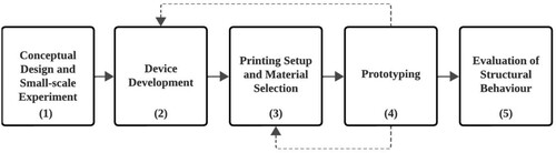
To achieve formwork-free 3DCP of spanning structures, this research follows a methodology comprising the following steps ():
Conceptual design and small-scale experiments: Initially, a conceptual framework was developed to validate the hypothesis. Variations in spanning structure designs printable with this technique were envisioned. Manual tensioning platforms were utilised to test the arrangement of cables within concrete filaments.
Device development: A custom device was designed, fabricated and programmed to enable semi-automated printing and reinforcing.
Printing setup and material selection: The required printing setup, including frames and pins, was designed and fabricated. The selection of material for the cables reinforcing the concrete filament was carefully considered.
Prototyping: The printing setup and custom device underwent multiple iterations to refine functionality and performance.
Evaluation of structural behaviour: The structural behaviour of the printed geometry was assessed, particularly focusing on the composite cross-section.
Figure 1. Methods diagram.
4. Detailed methodological steps and results
4.1. Conceptual design and small-scale experiments
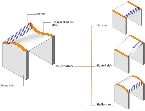
To verify the proposed hypothesis, a conceptual framework was developed, comprising three main steps: (a) printing the walls, (b) placing the pins and (c) winding reinforced self-supporting concrete filaments around the pins. illustrates these steps using the simplest printable geometry: a flat surface. Additionally, ruled surfaces, including flat and slanted surfaces, as well as shallow arches, can be constructed using this technique ().
Figure 2. Conceptual framework steps: (a) printing the walls, (b) placing the pins and (c) winding self-supporting concrete filament around the pins.
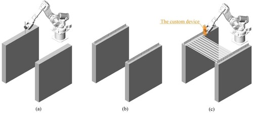
Figure 3. Design variations of spanning structure printable with the envisioned technique.
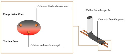
To determine the appropriate arrangement of cables within the concrete filament, the behaviour of spanning elements was considered. In spanning elements like beams, the bottom of the element is under tension while its top is under compression. This structural behaviour and the boundary conditions of the structure (external load, support reaction, allowable deflection, etc.) inform the arrangement and density of the cables. Based on these considerations and the width of the concrete filament, an arrangement of cables was devised: a single cable at the bottom of each filament for tensile strength and two rows of cables at the top to hinder the flow of the concrete and prevent it from falling (). By increasing the nozzle size and, therefore, the filament width, it is possible to include more cables, especially at the bottom, enhancing tensile strength. If several filaments are printed rows upon rows, the entire lowest row will be in tension under a loaded-beam condition.
Figure 4. Conceptual diagram of cable arrangement in a concrete filament.
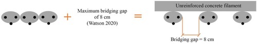
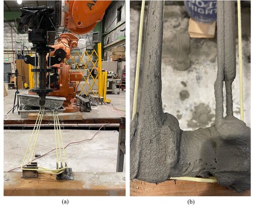
To validate the conceptual framework, a manual cable-tensioning platform was designed to tension and hold the cables and then concrete was printed on the top (). The concept worked as planned as bonding between the concrete and the cables was observed. Printing strategy adjustments were then made to accommodate the rotation space required around the pins, ensuring an 8-cm gap between filaments, which Watson [Citation7] showed could be bridged by perpendicular filaments printed on the top ().
Figure 5. Making and testing of the manual tensioning platform: (a) manual tensioning fixture and (b) printed concrete filaments.
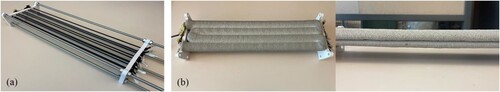
Figure 6. Printing strategy.
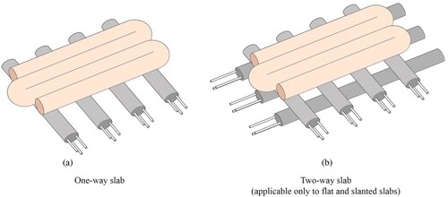
Subsequently, two printing arrangements for reinforced filaments were designed: one-way slab and two-way slab configurations (). The latter arrangement is only applicable to flat and slanted slabs since it is not possible to tension cables along a curve ().
Figure 7. Printing arrangements of reinforced filaments.
4.2. Device development
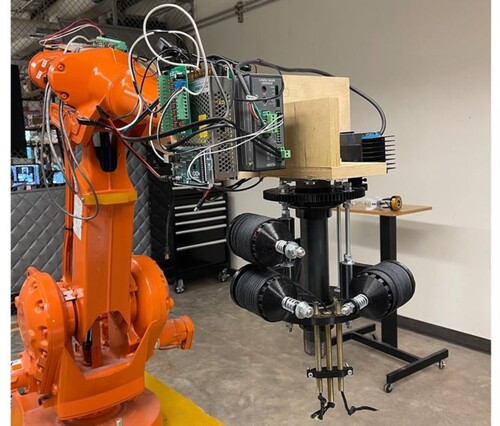
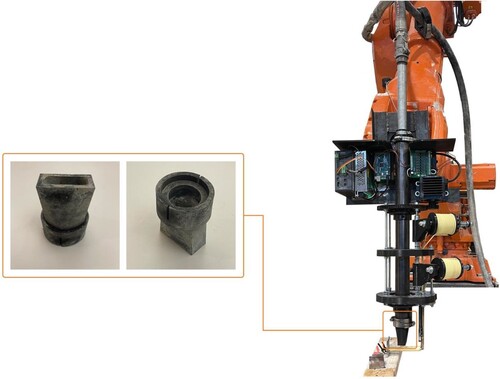
To automate and synchronise the cable-laying process during 3DCP, a custom device was developed (). This device attaches to a robotic arm without requiring additional adjustments to the printing hardware and consists of four distinct subsystems:
The chassis subsystem serves as the structural frame of the device, providing stability and support during the cable-laying operation.
The motion subsystem encompasses the mechanisms responsible for the precise and accurate cable-laying manoeuvre around the pins.
The cable-laying subsystem is designed to effectively deploy and position cables in the desired locations as part of the automation process. This subsystem ensures efficient and reliable cable placement without interfering with the 3DCP operation. Moreover, it tensions the cables using a mechanical brake with an adjusting nut to ensure that the printed filament does not deform.
The controlling subsystem encompasses the necessary hardware and programme responsible for governing the device. It manages the coordination between the robotic arm, the custom device and the 3DCP system to ensure synchronised operation.
Figure 8. The designed device.
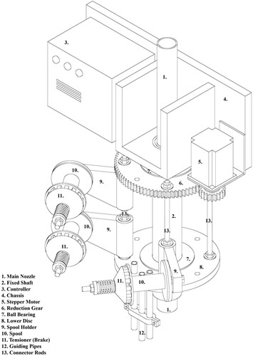
Figure 9. Operating workflow of the device.
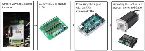
Figure 10. First iteration of the device.
4.3. Printing setup and material selection
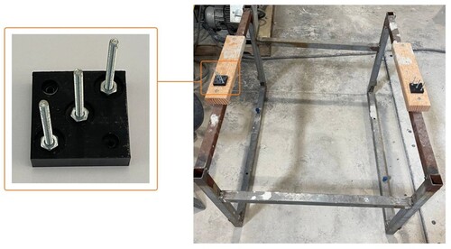
A 1-m-long welded frame, emulating the walls of an actual construction, along with supporting pins, was fabricated. This frame was fastened to the ground, ensuring stability during the 3DCP of the structure, and compatibility with the cable-laying device. The pins were designed to ensure a precise arrangement of the cables within the printed filament and safeguard its integrity during the printing process ().
Figure 11. Printing setup.
In all printing experiments, we maintained a consistent water-to-dry-mix ratio of 0.205. The dry mix we used was GCT Structural Mortar Mix 4000 psi [Citation28], which is a blend of Portland cement, pulverised limestone, lime, fibres and other additives (see for details). The maximum particle-size diameter of this mix is 1 mm, as outlined in . For the in-process reinforcement we used a basalt cable, Basalt 3-ply rope, made from three plies of 6400 tex 16-micron roving, totalling 19,200 tex and with a diameter of 5 mm (Smarter Building Systems LLC [Citation29], https://basaltroving.com) as well as Kevlar cables. The Kevlar cables we utilised were braided, had a diameter of 4.6 mm and weighed 10.0 g per metre (Emmakites [Citation30] https://www.emmakites.com/products/) Our printing setup comprised an industrial 6-axis robotic arm (ABB IRB 6640), a mixer – pump (m-tec Duomix 2000) and a silo containing the dry-mix material.
Table 1. Material composition and particle-size distribution – GCT material.
The printing process involved mixing the dry mix with water and then pumping the resulting mixture through a hose to a nozzle attached to the robotic arm. The arm deposited the material based on instructions coded in RAPID (the programming language for ABB industrial robots). These instructions were generated using the Grasshopper plug-in HAL. The initial printing parameters include water flow rate, extrusion rate, robot speed, nozzle size and toolpath design settings. The initial toolpath design considered a filament 15 mm high and 30 mm wide ().
Table 2. Initial printing and toolpath design settings.
4.4. Prototyping
The goal of this step was to refine the cable entraining device and the printing setup design through iterative testing, including two phases:
Dry-run: This phase included the manual installation of the pins on the printing platform, ensuring an 8-cm separation between each pin. Subsequently, the device was used to lay the tensioned cables between the pins, without any concrete deposition. This phase permitted the evaluation of the device’s functionality and the printing setup’s performance.
3DCP test: In this phase, concrete was deposited on the cables to assess the system’s performance under operational conditions, focusing on the device’s effectiveness in cable laying and the overall stability and accuracy of the printing setup. Moreover, the initial printing parameters () were updated during this phase to ensure reliable printing.
4.4.1. Iteration one
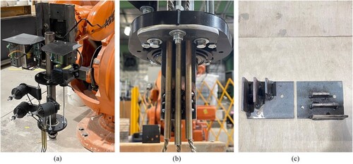
The first iteration revealed weaknesses in the design of the chassis, cable-laying system and pins. The wooden chassis showed insufficient stability during the dry run due to the applied tension on the cables via tensioners (.11). Likewise, guiding pipes (.12) and pins () needed more support to handle the tension on the cables. To overcome these shortcomings several modifications were implemented (): the wooden chassis of the device was replaced with a fully welded steel chassis, the cable-laying pipes were fortified through the incorporation of supporting plates, and the pins were replaced by steel plates welded onto a base plate.
Figure 12. Replaced components: (a) fully welded steel chassis, (b) stable guiding pipes with supporting plate and (c) fully welded pins made of steel plates.
4.4.2. Iteration two
In the second iteration, it was observed that the friction between the cable and the cable-laying pipes when the device moved around the pins caused the stepper motor to rotate by 180 degrees instead of 90 degrees as programmed. To overcome this problem, the basalt cables were replaced by Kevlar cables, which reduced friction, relieving resistance during rotation. Then, the tension applied to the cables was progressively reduced from 100 N to 30 N, by loosening the nut on the tensioner, and the driving mode of the stepper motor was changed from full step to half-step mode, which increased the torque output by 10%, enabling the stepper motor to overcome the resistance caused by the high cable friction.
4.4.3. Iteration three
These modifications led to a successful dry run during the third iteration. However, challenges arose during the 3DCP test as one of the top cables failed to be embedded in concrete (). This problem was attributed to inadequate extrusion of concrete from the main nozzle and the smaller diameter of the Kevlar cables compared to basalt cables.
Figure 13. Result of the third iteration: (a) successful dry-run and (b) unsuccessful 3DCP.
To rectify this problem, an adaptor was designed, fabricated and integrated into the device. The purpose of the adaptor was to increase the width of the concrete filament, thereby facilitating a proper embedment of the cables ().
Figure 14. Modifications implemented in the third iteration.
4.4.4. Iteration four
The implemented modifications led to a successful dry-run and 3DCP test. However, an insufficient bond between the cables and the concrete was identified when the robot speed reached 80 mm/s when moving away from the pins. This problem was not observed when the speed decreased to 20 mm/s to avoid collisions when approaching the pins. The last step in this iteration was to bridge the 8-cm gap between reinforced filaments with unreinforced filaments. According to Watson [Citation7], to successfully bridge this gap the printing speed was raised to 150 mm/s and deposition height set to 2.5 cm. The result of printing with these settings is shown in .
Figure 15. Final result of the c device: (a) printing reinforced filaments, (b) attaching end of the filament and (c) bridging.
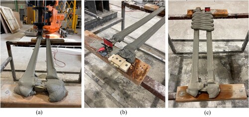
The final iteration validated the performance and effectiveness of the developed device, producing a successful print of a spanning structure (). These results demonstrate the viability of the developed device for practical construction applications, although further iterations are needed to scale up the process. Moreover, the initial printing parameters () were updated to the values shown in , resulting in successful printing results.
Figure 16. Final successful printed structure with the span of one metre.
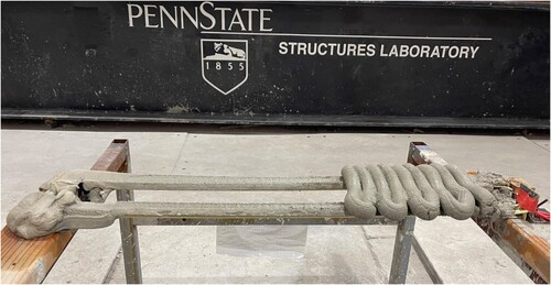
Table 3. Updated printing and toolpath design settings.
4.5. Evaluation of structural behaviour
This section evaluates the structural behaviour of the reinforced filament, focusing on the composite cross-section of the filament. Understanding the properties of both concrete and cables is essential for this evaluation. The concrete properties were derived from ASTM C109 [Citation31] and C78 [Citation32] tests. The compressive strength was measured at 21.20 MPa, and the modulus of rupture obtained from flexural tests reached 3.52 MPa. Tensile tests were conducted to assess the cable’s tensile strength, pullout tests were used to evaluate cable-concrete friction, and 4-point bending tests, along with numerical analysis (FEM), were performed to examine the filament’s behaviour under bending conditions.
4.5.1. Tensile test
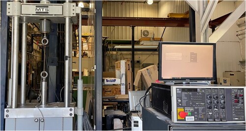
Although Kevlar was ultimately chosen as the selected reinforcing material in the prototyping step, a comparative analysis of its tensile strength was conducted alongside basalt cables, following the ASTM D2256 [Citation33] standard developed by the American Society for Testing and Materials (ASTM). The purpose of ASTM D2256 is to evaluate the mechanical strength and performance characteristics of cables used in different industrial applications. By subjecting the specimens to a uniaxial tension until they fail, this test method allows for the quantification of the material’s response to applied forces. The test involves preparing specimens according to specified dimensions and clamping them securely in a testing apparatus. The specimen is then subjected to a steadily increasing tensile force until it ruptures. shows the setup for tensile test in this study with an MTS machine.
Figure 17. Tensile test setup.
The results revealed that Kevlar demonstrated a tensile strength of up to 2921 MPa, whereas basalt exhibited a substantially lower tensile strength, reaching only 947 MPa. The stress – strain behaviour of Kevlar displayed a linear pattern leading to ultimate strength without any indication of strain hardening (). Failures primarily occurred near the attachment points, suggesting weakened areas likely due to cable knotting.
Figure 18. Stress-strain diagram of specimens with Kevlar and basalt cables in tensile tests.
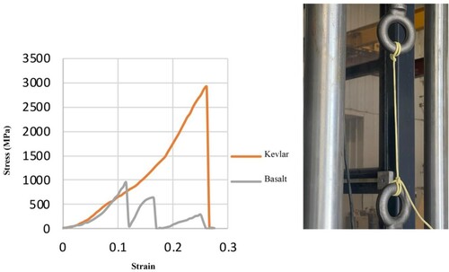
In contrast, the stress–strain behaviour of basalt showed significant deformation, characterised by a distinct pattern where woven fibres failed in three sequential clusters. In , the initial slope appeared lower than the modulus of elasticity due to cable tightening within the grip. Basalt cables are composed of three wire clusters twisted together within the cable structure. During testing, each of these clusters failed consecutively, resulting in three distinct peaks in the stress–strain curve. Notably, failures tended to concentrate near the hooks, indicating that the cables knotting around these points may have compromised their strength.
The modulus of elasticity for Kevlar was measured at 8.94 GPa, slightly higher than the 8.78 GPa observed for basalt until initial failure occurred. Due to challenges encountered during the prototyping phase and the lower performance in the tensile test, basalt cables were excluded from subsequent pullout and 4-point bending tests.
4.5.2. Pullout test
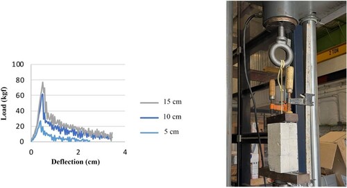
A pullout test assessed the interaction between cable and concrete. The deflection occurring between the MTS claws was utilised as an approximation for the deflection exhibited by the Kevlar cables. This assumption was made based on the minimal deflection exhibited by concrete compared to Kevlar. The purpose of the experiment was to evaluate the development length (length of reinforcement required to transfer the stresses between the reinforcing material and the surrounding concrete) and determine the friction between materials based on the length of the reinforcement embedded in the concrete. To achieve this, prism samples were prepared with square sections measuring 5, 10 and 15 cm in height. During concrete pouring, cables were under 30 N tension. After casting the molds, with the same concrete used for printing, specimens were cured for 7 days, and underwent the pullout test with an MTS machine. The load applied to the samples varied for depths of 5, 10, 15 cm, with the corresponding values being 26.8, 61.6 and 76.7 kgf, respectively. Bond stress between concrete and Kevlar was also determined, resulting in values of 0.42, 0.49 and 0.40 MPa for the respective sample heights. As the depth of the embedded cables decreases from 15 to 10 to 5 cm, the shear stress values increase slightly. Specifically, the shear stress for the 10 cm depth is 22.5% higher than that of the 15 cm depth. Similarly, the shear stress for the 5 cm depth is 5% higher than that of the 15 cm depth. Based on the results, in none of the samples did the Kevlar fail before coming out of the concrete, indicating that the development length is higher than the embedment length in all samples. This result was expected due to the significantly higher strength of Kevlar compared to steel, in addition to the lower surface contact between concrete and reinforcement. Therefore, the development length can be calculated using extrapolation. In this study, the pull-out test was conducted to obtain the shear stress between concrete and Kevlar. shows the result of this test.
Figure 19. Kevlar pullout test.
4.5.3. 4-point bending test and numerical analysis (FEM) of flexural capacity
The flexural capacity of the filament was determined through the ASTM C78 [Citation32] flexural test and numerical analysis (FEM). In the ASTM C78 test, 24-cm-long samples underwent a 4-point bending test using an MTS machine. Testing involved three sample types: well-bonded samples for which concrete covered at least 40% of the cable surfaces; weak-bonded samples; and without-cable samples. Bonding quality is influenced by factors such as temperature and printing speed, and it may not remain consistent throughout the printing process, with changes in printing speed near the supports and larger displacement in the middle of the section due to the rotation of cables at the supports. However, measurements showed that tension applied during cable implementation reached 3 kgf, maintained after concrete sets. This amount of tension was the maximum load that the motion subsystem of the device could handle, and further development needs to be implemented to increase the tension. Moreover, after the cables were removed from the supports, they did not slip, indicating that the friction was sufficient for maintaining the applied tension. shows the results of flexural strength tests and the FEM analysis.
Figure 20. – Results of the flexural strength test and FEM analysis.
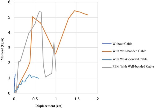
In the FEM model the material properties of Kevlar cables were defined based on the tensile test, and Concrete Damage Plasticity (CDP) properties were determined from the normalised results of compression and tension tests ( and ). The interaction between concrete and cables was characterised as cohesive behaviour with damage, instead of being defined as tied, as debonding failure was observed during the 4-point bending test (). A traction-separation model was used to model the cohesive contact between cable and concrete. The behaviour in both hardening and degradation assumed to be linear. The stiffness matrix for Traction-separation model is obtained from the pull-out test based on the applied load and displacement. The correlation between experimental and FEM results is satisfactory, displaying close maximum moment capacities and similar cracking patterns. However, results deviate slightly due to uncertainties in bond behaviour. The stress distribution in cables and the concrete section is shown in .
Figure 21. Experimental and normalised Concrete Damage Plasticity (CDP) properties.
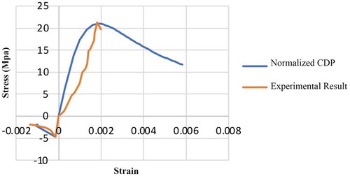
Figure 22. The failure of reinforced filament in experimental conditions (top) and FEM simulation (bottom).
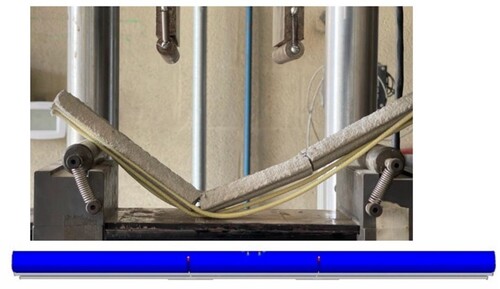
Figure 23. Von mises stress in concrete and cable section at the highest moment capacity (first peak).
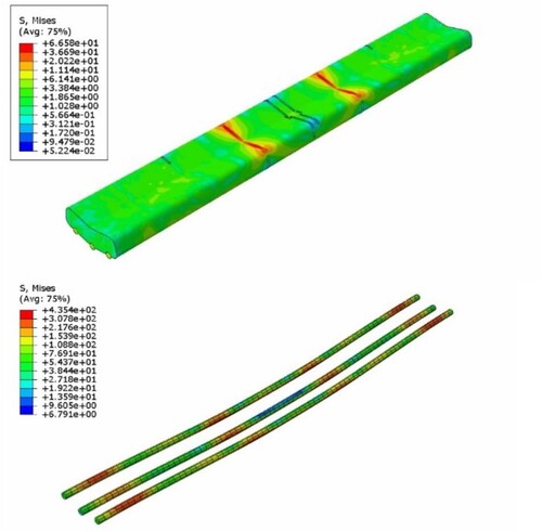
Table 4. Concrete damage plasticity parameters.
In the well-bonded samples, failure occurred due to the loss of contact between the concrete and the bottom cable. Subsequently, the lateral cables also failed in the second peak in . A similar pattern was observed in the FEM model. In these samples, debonding of the bottom cable initiated from the point of applied load at the top and extended towards the middle of the section. In the weak-bonded samples, contact between the concrete and cables is minimal. Only when the actuator pushes the sample down does pressure develop on the bottom cables at the supports. Following the slippage of the bottom cable on the support, the entire structure experiences complete failure. The well-bonded samples demonstrate a moment resistance 4.1 times higher than weak-bonded samples.
The FEM model revealed a comparable failure pattern in the cable debonding process. In well-bonded samples, this occurs precisely under the applied load, directly beneath the crack in the concrete section. The initial failure is characterised by a higher maximum stress in the bottom cable, indicating the early loss of contact for that cable. In both experimental and numerical analyses, well-bonded samples exhibit two peaks. However, the maximum moment in the FEM model for the second peak is only 61% of the maximum moment observed in the experimental test.
In summary, failure patterns were observed in both experimental and numerical analyses, with well-bonded samples demonstrating higher moment resistance compared to weak-bonded samples. The FEM model showed a comparable failure pattern, though with some deviation due to uncertainties in bond behaviour. Well-bonded samples exhibited two peaks in both experimental and numerical analyses, with the latter showing a slightly lower maximum moment.
5. Discussion
The work described in this paper is part of a larger study aimed at developing a formwork-free, semi-automated process for 3DCP spanning structures. The primary objective is to print spanning structures with reduced concrete consumption and minimal waste by incorporating tensioned cables into concrete filaments during printing. The cables serve as supporting agents, but they also provide some level of reinforcement as the load-bearing capacity and the performance of the printed filaments significantly improved compared to filaments without cables, even with a weaker bonding.
Although not the same as pre-tensioned concrete, as the cables do not transfer prestressing to concrete, the proposed approach can mimic the behaviour of pre-tensioned cable-supported concrete, depending on the tension applied by a robotic arm during printing or improvements in bonding. Ensuring that cables do not slip out is essential for optimising the structural capacity of such elements. This goal can be achieved by investigating cable types with superior bonding or by fully embedding the cables within the concrete.
The process is independent from the type of concrete as long as pumpable concrete is used. However, further exploration is needed to ensure that different cable materials can be unwind and, more importantly, that structural requirements are met. In the current study, Kevlar was selected over Basal as it displayed lower friction with the cable laying system and higher tensile strength. Future modifications to the system may facilitate the use of different cable materials. While the process with Kevlar cables was successful, challenges remain regarding long-term functionality and implementation of the cable entrainment device, namely:
Bonding: The bond between concrete and the cables requires improvement for effective load transfer and enhanced structural integrity. Exploring different supporting/reinforcing materials with better friction bonding, coting cables with adhesive chemical, optimising printing parameters and multilayer printing, in which cables are fully embedded in the second layer, are potential solutions. Addressing this shortcoming is important for scalability.
Pin fabrication, placement and calibration: The manual fabrication, placement and calibration of pins present difficulties concerning the lead time and accuracy of the process. Utilising more reliable fabrication tools and implementing robotic placement methods are recommended. In the first possible solution, pins manufactured through mass production techniques (CNC milling, or metal casting and machining) are placed via a robotic arm either while the concrete is wet or after it dries. In the second solution, all the pins are installed on a steel plate, and the whole plate is placed on the wall either on the wet or dry concrete. The second strategy can streamline the calibration process as all pins can be fabricated and installed on a plate in a factory-controlled environment. Moreover, while bolting on dry concrete may add automation cost to the project, as it requires designing a custom tool to drill holes and insert supporting rebars to secure the pins, placing on the wet concrete may be more practical as a simple gripper can handle the pick and place process.
Control subsystem: This challenge was identified when the device collided with one of the pins during a dry run. The operator was able to act swiftly, stop the robotic arm and turn off the tool; however, this is a major safety challenge that needs to be addressed to improve the long-term reliability and functionality of the device. A proposed solution is implementing a closed-loop control system connected to a continuity detector that can shut off the whole system if the device touches the pins, thus preventing further damage. This closed-loop control system can also improve other functionalities of the device, namely the cable laying subsystem. In the current version, the tension is applied to the spools by a mechanical brake that can be tightened manually with a bolt and spring (.11). However, to maintain consistent tension on the cables and adjust them on demand, an electromagnetic brake connected to a load cell can be implemented. The load cell can monitor the tension on the cables, send signals to the closed-loop control system and prevent overloading the motion subsystem of the device and the robotic arm by adjusting the tension via the electromagnetic brake.
Nozzle size: The current nozzle diameter imposes limitations on the incorporation of additional cables, particularly at the bottom of the filament, which has the potential to enhance structural performance. This challenge can be overcome by increasing the nozzle diameter.
Table 5. Early-stage comparison of the ecological footprint of processes for making a slab.
6. Conclusion
6.1. Contributions and findings
The proposed process for entraining cables in 3DCP filaments using a custom device offers enhanced flexibility in both the design and construction of spanning structures without formwork. Introducing tensile-supporting elements that also improve flexural strength into 3DCP represents a novel approach that leverages traditional construction principles to improve structural integrity. A flexible reinforcing material, namely Kevlar, has shown promise in enhancing structural performance through proper tensioning as reinforced filaments exhibited a significant increase in flexural strength, from 1.2 kgf·m to 5.0 kgf·m, compared to non-reinforced filaments. The proposed process potentially reduces the ecological footprint of concrete construction compared to other methods for making slabs. In summary, the research results strongly indicate the potential for widespread application of this technology in 3DCP.
6.2. Future work
While this study has demonstrated the effectiveness of the proposed process for constructing spanning structures, several challenges remain. Future work should focus on a detailed failure analysis of the proposed method based on shortcomings identified in Section 5. They can be categorised into four main areas: printing setup, device design, structural and safety. summarises these challenges, causes, and future considerations.
Table 6. Challenges and future considerations.
Furthermore, while this study focused on examining the behaviour of cable-reinforced concrete filaments to demonstrate the viability and potential of the proposed cable-entraining method for printing spanning structures, future research should explore larger, multifilament and multilayer elements such as slabs or roof structures. This will help verify the effectiveness of the proposed method for constructing spanning structures.
Data statement
The data that support the findings of this study are openly available in Data for paper ‘3D Concrete Printing of Self-Supported Filaments via Entrained Cables: Constructing Formwork-Free Spanning Structures’ at doi:10.26207/7yzb-je50.
Supplemental Material
Download MS Word (5.5 MB)Supplemental Material
Download MS Word (13.2 KB)Supplemental Material
Download MS Word (15.6 KB)Supplemental Material
Download JPEG Image (2.1 MB)
Acknowledgements
The authors express their gratitude to Dr. Aleksandra Radlińska, Mr. Nathan Watson, Dr. Gonçalo Duarte, Ms. Paniz Farrokhsiar, Ms. Nusrat Tabassum, Mr. Ali Alhussain, Mr. Mohamed Raeez Akhtar Sadik, Mr. Hanbin Cheng, Mr. Zhengyu Wu and Mr. Anand Swaminathan for their valuable insights and contributions to this research.
Disclosure statement
Three of the co-authors, Sven Bilén, Jose P. Duarte, and Shadi Nazarian, have equity in a company, X-Hab 3D, whose activity is concrete printing. This relationship is currently under management by their respective university’s conflict of interest offices.
Additional information
Funding
References
- Paul SC, Van Zijl GP, Tan MJ, et al. A review of 3D concrete printing systems and materials properties: current status and future research prospects. Rapid Prototyp J. 2018;24(4):784–798. doi:10.1108/RPJ-09-2016-0154
- Abdalla H, Fattah KP, Abdallah M, et al. Environmental footprint and economics of a full-scale 3D-printed house. Sustainability. 2021;13(21):11978. doi:10.3390/su132111978
- Mohammad M, Masad E, Al-Ghamdi SG. 3D concrete printing sustainability: A comparative life cycle assessment of four construction method scenarios. Buildings. 2020;10(12):245. doi:10.3390/buildings10120245
- Bos F, Wolfs R, Ahmed Z, et al. Additive manufacturing of concrete in construction: potentials and challenges of 3D concrete printing. Virtual Phys Prototyp. 2016;11(3):209–225. doi:10.1080/17452759.2016.1209867
- Nematollahi B, Xia M, Sanjayan J. Current progress of 3D concrete printing technologies. In: ISARC. Proceedings of the international symposium on automation and robotics in construction. Vol. 34. Taipei: IAARC Publications; 2017. p. 260–267.
- Tejeda-Dominguez F, Lange DA, D’Ambrosia MD. Formwork pressure of self-consolidating concrete in tall wall field applications. Transp Res Rec. 2005;1914(1):1–7. doi:10.1177/0361198105191400101
- Watson N. Concrete additive manufacturing system design for earth and mars. MS Thesis in additive manufacturing and design, The Pennsylvania State University. 2020.
- Gantner S, Hack N, Amiri F. Integration of individualized prefabricated fibre reinforcement in additive manufacturing with concrete. AMC TRR277, 2024. https://amc-trr277.de/research-summary-report-of-a05-2/, accessed on June 13, 2024.
- Bhooshan S, Bhooshan V, Dell’Endice A, et al. The striatus bridge: computational design and robotic fabrication of an unreinforced, 3D-concrete-printed, masonry arch bridge. Archit Struct Construct. 2022;2(4):521–543. doi:10.1007/s44150-022-00051-y
- Salet TA, Ahmed ZY, Bos FP, et al. Design of a 3D printed concrete bridge by testing. Virtual Phys Prototyp. 2018;13(3):222–236. doi:10.1080/17452759.2018.1476064
- Duarte G, Brown N, Memari A, et al. Learning from historical structures under compression for concrete 3D printing construction. J Build Eng. 2021;43:103009. doi:10.1016/j.jobe.2021.103009
- Twente Additive Manufacturing. Twente additive manufacturing. https://www.twente-am.com/, accessed on April 18, 2024.
- Ahmed Z, Biffi A, Hass L, et al. 3D concrete printing-free form geometries with improved ductility and strength. In: Bos FP, Lucas SS, Wolfs RJM, Salet THM, editors. RILEM international conference on concrete and digital fabrication. Eindhoven: Springer; 2020. p. 741–756.
- Wu Z, Memari AM, Duarte JP. State of the art review of reinforcement strategies and technologies for 3D printing of concrete. Energies. 2022;15(1):360. doi:10.3390/en15010360
- Bos F, Ahmed ZY, Jutinov ER, et al. Experimental exploration of metal cable as reinforcement in 3D printed concrete. Materials (Basel). 2017;10(11):1314. doi:10.3390/ma10111314
- Marchment T, Sanjayan J. Mesh reinforcing method for 3D concrete printing. Autom Constr. 2020;109:102992. doi:10.1016/j.autcon.2019.102992
- Mechtcherine V, Nerella VN. Incorporating reinforcement in 3D-printing with concrete. Beton-Und Stahlbetonbau. 2018;113(7):496–504. doi:10.1002/best.201800003
- Mechtcherine V, Michel A, Liebscher M, et al. Extrusion-Based additive manufacturing with carbon reinforced concrete: concept and feasibility study. Materials (Basel). 2020;13(11):2568. doi:10.3390/ma13112568
- Asprone D, Auricchio F, Menna C, et al. 3D printing of reinforced concrete elements: technology and design approach. Constr Build Mater. 2018;165:218–231. doi:10.1016/j.conbuildmat.2018.01.018
- Freund N, Dressler I, Lowke D. Studying the bond properties of vertical integrated short reinforcement in the shotcrete 3D printing process. In: Bos FP, Lucas SS, Wolfs RJM, Salet THM, editors. Second RILEM international conference on concrete and digital fabrication: digital concrete 2020 2. Eindhoven: Springer; 2020. p. 612–621.
- Hass L, Bos F. Bending and pull-out tests on a novel screw type reinforcement for extrusion-based 3D printed concrete. In: Willmann J, Block P, Hutter M, Byrne K, Schork T, editors. Second RILEM international conference on concrete and digital fabrication: digital concrete 2020 2. Zurich: Springer; 2020. p. 632–645.
- Ayres P, Leal da Silva WR, Nicholas P, et al. SCRIM–sparse concrete reinforcement in Meshworks. Robotic fabrication in architecture, art and design 2018: foreword by Sigrid Brell-Çokcan and Johannes Braumann, Association for Robots in Architecture, 207–20. 2019.
- Hack N, Dörfler K, Walzer AN, et al. Structural stay-in-place formwork for robotic in situ fabrication of Non-standard concrete structures: A real scale architectural demonstrator. Autom Constr. 2020;115:103197. doi:10.1016/j.autcon.2020.103197
- Hack N, Bahar M, Hühne C, et al. Development of a robot-based multi-directional dynamic fiber winding process for additive manufacturing using shotcrete 3D printing. Fibers. 2021;9(6):39. doi:10.3390/fib9060039
- Taha N, Walzer AN, Ruangjun J, et al. Robotic AeroCrete–a novel robotic spraying and surface treatment technology for the Production of Slender Reinforced Concrete Elements. In, 3:245–54. CumInCAD. 2019.
- Kloft H, Empelmann M, Oettel V, et al. Production of the first concrete and reinforced concrete columns by means of 3D printing with concrete. BFT Int. 2019;85(6):28–37.
- Kloft H, Empelmann M, Hack N, et al. Reinforcement strategies for 3D-concrete-printing. Civ Eng Des. 2020;2(4):131–139. doi:10.1002/cend.202000022
- GCT Structural Mortal Mix 4000 PSI FS. Gulf Concrete Technology: Long Beach, MS, November 2018.
- Smarter Building Systems LLC. Basalt Roving. Basalt Guru from Smarter Building Systems LLC. Accessed April 5, 2024. https://basaltroving.com/, accessed on April 18, 2024.
- Emmakites. Braided Kevlar line utility cord. https://www.emmakites.com/products/100-2000lb-braided-kevlar-line-utility-cord, accessed on April 18, 2024.
- ASTM C109. Standard test method for compressive strength of hydraulic cement mortars (Using 2-in. or [50-mm] Cube Specimens). ASTM International. 2020.
- ASTM C78. Standard test method for flexural strength of concrete (using simple beam with third-point loading). ASTM International. 2009.
- ASTM D2256. Standard test method for tensile properties of yarns by the single-strand method. American Society for Testing and Materials. 2022.