?Mathematical formulae have been encoded as MathML and are displayed in this HTML version using MathJax in order to improve their display. Uncheck the box to turn MathJax off. This feature requires Javascript. Click on a formula to zoom.
ABSTRACT
Phase transformation is a crucial factor that determines the quality and deformation of components in laser-directed energy deposition (L-DED). Owing to the limitations of in situ observation methods, there is a lack of effective means to study the complete phase transformation and their impacts on deformation during the deposition process. In this study, multilayer heterogeneous deposition was investigated with the high-carbon high-speed steel by modelling the coupled phase transformation-thermomechanical physics. The methodology was proposed to identify the specific phase transformations by iteratively comparing the whole deformation history between digital image correlation (DIC) measurements and simulations. Besides the thermo-mechanical coupling effect and basic volumetric phase transformation, carbon partitioning between precipitated carbides and matrix was manifested, which also resulted in a rise of the Ms point by 208.4 °C and a reduction of the transformation rate by 73.2%. Additionally, an increase of 13.8% in energy absorption could be attributed to the surface oxidation of the deposited layer. The model predictions exhibited good consistency with the DIC in-situ measurement data, indicating that the deformation history contained sufficient information on the phase transformations. Based on the proposed transformation-thermomechanical coupling model, it helps to understand the complete phase transformation during deposition.
1. Introduction
Laser-directed energy deposition (L-DED), with its high energy and mass input rate and flexible deposition conditions, has been widely used in the repair, surface strengthening, and additive manufacturing of large-scale components [Citation1, Citation2]. Owing to the unique thermal cycle history, the formation and evolution of the microstructure in L-DED are complex and fundamental [Citation3, Citation4]. Two basic types of solid-state phase transformations occur in most alloy systems during multiple thermal cycles: displacive transformations induced by lattice structure transitions, and massive transformations induced by secondary phase precipitation and dissolution [Citation5, Citation6]. These transformations significantly impact the mechanical properties and final shape of the components [Citation7]. The residual austenite content decreased from 13.2% to 5.4% with an increase in the input energy density during the DED of H13 steel. Simultaneously, the concentrations of Cr, Mo, and V increased noticeably at the grain boundaries. The experimental results demonstrated that the phase transformation in the core region of the component was mainly attributed to thermal accumulation from the multilayer depositions [Citation8]. For duplex stainless steels, the γ phase fraction can be adjusted by controlling the deposition temperature. In the case of SAF 2507 duplex stainless steel, the diffusion of N and Ni is also an important factor influencing the course of the deposited phase transformation [Citation9].
It remains challenging to determine the complete phase transformation history of actual components. The post-deposition microstructure characterizations, e.g. SEM, TEM, EBSD, etc., are the general methods to figure out phases formed in L-DED processes [Citation10, Citation11]. Nowadays, the high-energy synchrotron X-ray diffraction (HEXRD) techniques has been tried to identify phase transformations in situ, which, however, impose strict limitations on the wall thicknesses of the deposited components [Citation12, Citation13]. Besides, the temperature-based analysis is an indirect method because phase transformations are dominated by thermal gradients, cooling rates and thermos cycles [Citation14, Citation15]. However, the temperature distribution and its variation during the DED process are difficult to obtain accurately because of the nonlinear emissivity at high temperatures in infrared imaging [Citation16], slow response time of thermocouples [Citation17], and lack of three-dimensional distributions [Citation18].
The phase transformations and deformation history exhibit strong interrelationships, as the former can be reviewed by the latter. inhomogeneous phase transformations [Citation19, Citation20], external constraints, and uneven thermal expansion [Citation15, Citation21] result in a deformation history of the deposited component. Austenitic and martensitic phase transitions respectively compensate the expansion during heating and contraction during cooling for materials with displacive transformations such as steel, nickel alloys [Citation22]. Compared to direct characterization of phase transformations aforementioned, the deformation history can be measured in situ using the digital image correlation (DIC) method with high accuracy and repeatability [Citation23, Citation24]. It is feasible to convert the characterization of complex phase transformations to an analysis of the deformation history, which may provide a practical approach to understanding material evolution in the deposition process.
Modelling and simulation provide theoretical methods for understanding physics in L-DED processes. However, few numerical models took comprehensive consideration on both phase transformations and thermo-mechanics[Citation25, Citation26], resulting in significant discrepancies between the model predictions and the actual processes. Currently, in numerical modelling research on DED, the most common approach is the thermomechanical coupling model, which relates the transient temperature field to thermal strains [Citation27–31]. These models consider the influence of external constraints, temperature boundary conditions, and material properties. They are primarily used for deformation and stress predictions [Citation32], as well as for optimizing deposition processes and paths [Citation33, Citation34]. Currently, many studies support the evolution of metal material microstructures and related classical phase transformation models in processes such as welding and heat treatment [Citation35–39]. Compared with the aforementioned processes, the temperature variations in DED exhibit distinct characteristics of thermal cycling and thermal accumulation, and relatively less research has been conducted on the corresponding phase transformations in DED [Citation40]. A review article in Progress in Materials Science suggests that the numerical modelling of microstructural evolution in steel during additive manufacturing is still in its early stages [Citation41]. Previous studies have mainly focused on predicting martensitic phase transformations during cooling [Citation25, Citation26]. Other phase transformations resulting from thermal accumulation, such as bainitic transformations, martensite tempering, and secondary phase precipitation, were not considered. In particular, the coupled relationship between the phase transformations and deformation has not been investigated in depth.
This paper proposes a research methodology that inversely analyzes and infers the sequence and products of the phase transformations by iteratively comparing the simulations and DIC in-situ deformation data during the L-DED process. For high-speed steel, a multilayer deposition thermomechanical-phase transformation coupling model incorporating basic phase transformation kinetics was established. An accurate deformation history during the L-DED process was obtained using DIC. By comparing the simulated and measured deformation curves as well as microscopic observations, the phase transformation features influencing deformation were analyzed and demonstrated, thus obtaining elaborate information on phase transformations. The model considers changes in the carbon content of the matrix owing to carbide precipitation, nonlinear martensitic phase transformation rates, variations in energy absorptivity caused by surface oxidation, and autotempering. Both the simulated calculations and experimental results demonstrate that the complex phase transformation processes in L-DED high-speed steel significantly influence deposition deformation, and the deformation history helps elucidate the intricate phase transformation behaviour.
2. Experiment and method
2.1. Methodology
This study proposes a methodology to identify the phase transition of the deposition process from the deformation history, the outline of which is shown in . Firstly, the CCT and TTT curves of the deposited materials are obtained by the dilatometry test and the kinetic parameters of the phase transformation of the deposited material are fitted. On this basis, the Gleeble test is designed to obtain the single-phase stress–strain curves of the deposited material and to fit its single-phase constitutive model. Based on the obtained phase transformation kinetic model and single-phase constitutive models, the base model of thermomechanical phase transformation coupling is built and the deformation histories of the substrate under the determined deposition process parameters are obtained using ABAQUS and DANTE software.
Figure 1. Research framework for this study.
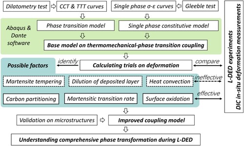
Laser deposition experiments are performed based on the process parameters used in the coupled model, while experimental data on the deposition deformation history are obtained by in-situ DIC deformation measurements. The experimental deformation data are compared with the calculated results of the base model and the differences between the experiments and the calculations are used to identify possible factors such as carbide precipitation and dilution of the deposited layer. The possible influencing factors are corrected in the base model and the deformation curves are calculated, and the effective influencing factors are iteratively screened. At the end of the identification process, an improved coupling model is obtained and validated by microstructure experiments. This iterative process realises the identification of the phase transition history of deposition by deformation.
2.2. L-DED equipment and parameters
In this study, deposition experiments were conducted using a powder-based L-DED process. The deposition system mainly consisted of a TruDisk 4002 laser system (TRUMPFTM disk laser with a maximum power of 4000 W), TruDisk D70 (TRUMPFTM) three-channel coaxial powder laser head, Kuka industrial robot, a powder feeder, and a protective gas delivery system. The overlay system is illustrated in .
Figure 2. Powder-based L-DED system configuration.
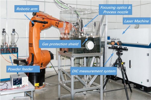
In the experiments, the laser spot diameter was set to 2.5 mm with a focal length of 16 mm. A defocusing of 1 mm was applied. Material deposition was accomplished using a powder feeder driven by high-purity argon gas at an adjustable pressure. The carrier gas flow rate was set at 9 L/min. During the overlay process, the molten pool area was protected by a direct flow of high-purity Ar gas at a rate of 20 L/min.
The deposition material used in this study was T15 high-speed steel (ASTM A600), which is known for its high hardness, excellent corrosion resistance, and superior wear resistance, making it suitable for strengthening component surfaces. The substrate material was 4140 steel (ASTM A29), which is commonly used as a structural material for base components. The elements in T15 and 4140 materials used in the experiment were measured using a direct-reading optical emission spectrometer and inductively coupled plasma optical emission spectrometry (ICP-OES). The chemical compositions of the materials are listed in .
Table 1. Elemental composition of 4140 and T15 materials (wt%).
Extensive process parameter optimization experiments were conducted in the preliminary stage to achieve dense and defect-free deposition layers. The final optimized set of process parameters is listed in . The subsequent experiments and modelling were based on this optimized parameter combination.
Table 2. Optimal operating parameters for multilayer L-DED of T15 steel.
2.3. In situ measurement of deformation history
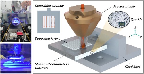
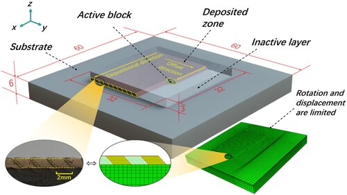
To accurately evaluate the deformation history of the substrate during the L-DED process, we designed an in situ measurement experiment based on the principles of 2D-DIC. The 2D DIC system has a static error of ±4 μm. Within a deformation range of 10 mm, the measurement error of the system is 0.012 mm, which is 0.12% of the measurement range. The experimental setup is shown in . The test surface was uniformly sprayed with high-temperature-resistant white paint and speckle patterns ranging from 30 to 80 μm in size. Speckle patterns were used to identify and calculate the displacement field of the test surface. The substrate used in the experiment had dimensions of 60 × 60 × 6 mm3. Three layers were deposited, each consisting of 16 passes. The length of each deposition pass was 32 mm, the pass offset was 2 mm, and the deposition strategy was linear, as shown in . The return stroke of the laser head resulted in a cooling interval of 3.67 s between consecutive deposition passes in the same layer. The deposition width of a single pass was approximately 3.2 mm and at the end of the deposition a 32 × 32 × 3 mm3 layer is formed. With the experimental process parameters, the depth of the melt pool is about – 0.38 mm, there were two cooling intervals between the layers at 3 and 30 min, and according to our previous calculations on the multiphase flow of T15 L-DED [Citation42], the dilution in the first deposited layer was about 17% and the T15 mass fraction in the second deposited layer was 0.971.
Figure 3. In situ measurement experiments of substrate deformation.
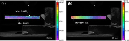
During the laser input process, the visible light emitted by the molten pool can obscure the speckle patterns captured by a camera. To ensure the accuracy of the experimental results, the moments during which the camera was affected by the incident laser were not used in the deformation calculation. Instead, these intervals were linearly connected based on the deposition time to ensure continuity of the data. When the speckle patterns are effectively recorded, the lateral displacement field can be analyzed with a subset of 117 pixels. The sigma (σ) uncertainty interval represents the quality of the data, as shown in (a). The maximum value of σ is 0.0056, which is significantly less than the typical quality requirement of 0.02. To investigate the displacement variations throughout the entire L-DED process, point P0 near the free end of the substrate, close to the boundary, was selected as the research position. The sampling location is shown in (b), where V is the vertical displacement at point P0, and the displacement curve at this point during the L-DED process is plotted further.
Figure 4. Data quality evaluation and depositional deformation analysis of DIC in-situ monitoring. (a) Measuring error evaluation; (b) Displacement field and location of sampling point P0.
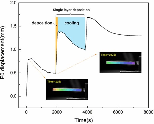
shows the displacement variation curve of the free end of the substrate during L-DED. The displacement curve demonstrates that because of the periodic input of energy into the deposition system, the free end exhibits an approximately linear periodic increase during deposition. However, during the interlayer cooling phase, the free end of the substrate undergoes a certain degree of deformation recovery. Additionally, based on the displacement measurement curve, the depositional deformation behaviour of each layer exhibited similarities and repeatability. Therefore, each deposition layer can be considered as a complete deposition unit.
Figure 5. In-situ measured displacement curve of sampling point P0 in the substrate.
Furthermore, during the deposition process, each deposition pass and interpass cooling can be considered a fundamental process subunit. shows the displacement curve of the substrate for the first 4 passes during a single layer deposition. In the experiment, the complete layer-deposition process consisted of multiple cycles of laser input (simultaneous mass addition) and cooling. Each cycle involved two thermal boundary conditions, namely laser heating and interpass cooling.
Figure 6. Experimental substrate deformation values and trends under intermittent thermal cycling.
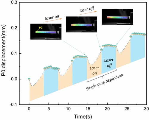
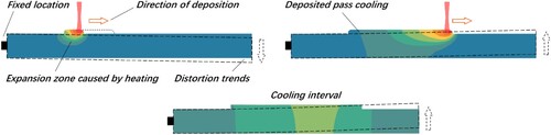
Under a single thermal cycle, the deformation of the free end of the substrate (P0) can be divided into three stages, as schematically shown in . These stages are as follows. 1) Initial Laser Input: At the beginning of the deposition near the fixed end, the initial region of deposition expands under thermal input, causing the free end to bend downward. 2) Late laser input: Toward the end of the laser input, as the heat source moves forward, the cooling and contraction of the deposition pass causes the free end to bend upward. 3) Intermittent Cooling: After the cessation of heat input, the heated substrate undergoes air cooling and contraction. The high-temperature region is farther from the fixed end, resulting in a slower recovery of the free end compared to the laser input stage.
Figure 7. Schematic of substrate deformation during a single thermal cycle.
3. Base model on thermomechanical-phase transformation coupling
3.1. Deposition geometry and temperature boundary conditions
In this study, the computational domain of the L-DED included a AISI 4140 substrate and T15 deposited layers with specific dimensions, as shown in . Geometric modelling and meshing was carried out using Abaqus finite element software. The model contains a total of 60,192 hexahedral meshes with mesh sizes between 0.5 and 1 mm at key locations. The model incorporates the continuous mass addition process of deposition by discretely adding the deposition layer in both the temporal and spatial domains. To describe the overlap ratio between the deposition passes, the added block section shape was set as a parallelogram, with its geometric dimensions based on the experimental deposition pass cross-sectional geometry under the same process conditions (as shown in the magnified region of ). The mechanical boundary conditions were set according to the experimental conditions, as shown in . The rotation and displacement of the substrate is limited at the centre axis part of the substrate.
Figure 8. Geometry and mechanical boundary conditions of the model computational domain (unit: mm).
This model takes into account the effects of local thermal expansion as well as local inhomogeneous phase transitions on the deformation of the substrate, and the stress equilibrium between the deposited layer and the substrate of the deposition process produces the complex deformation history. The modelling approach employed the concept of tracking elements to implement material addition in the model. This indicates that the predefined coordinates of mass deposition were implemented using empty elements, allowing them to adapt and change with the deformation of the substrate. This approach avoids the relative positional errors that can occur when activating a mass based on fixed coordinates.
In the L-DED process, the heat generated by the laser is dissipated in three modes: conduction, convection, and radiation. In a deposition system where a moving laser serves as the heat source, the temperature within the material is described using the heat balance equation for isotropic solid-state heat transfer [Citation43].
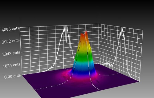
The BeamGage beam quality analyzer (SpiriconTM) was used to attenuate and measure the energy distribution of the low-power beam, and the three-dimensional energy distribution is shown in . Based on the measurement results, a Gaussian heat source model [Citation44]was employed to simulate the energy input. The model expression is given by EquationEq. (1)(1)
(1) , where q is the laser power, η is the laser absorptivity, r0 is the spot radius, and λl is the laser intensity factor. After fitting, the laser intensity factor λl of the model was determined to be 3.1.
(1)
(1) Due to the laser heating of the powder during the flight process and to address the issue of temperature discontinuity caused by discrete mass addition, the model sets the initial temperature of the discrete mass above the material's melting point at 1350 °C. Based on our previous research [Citation45] and considering the actual physical processes involved, the energy absorptivity during the deposition process was calculated using a forward model. Considering the discrete mass with its initial temperature in this model, a correction was made to the energy absorptivity η in EquationEq. (1)
(1)
(1) , yielding a calculated value of 0.46.
Figure 9. Energy distribution curve of measured laser.
The formation of the molten pool is accompanied by energy dissipation, so convection and radiation must be considered in the calculation. The Newton's law of cooling is used to describe thermal convection on the surface of the substrate, and the Stefan–Boltzmann law is used to describe the heat flux density of thermal radiation from the substrate to its surroundings. The total energy dissipation can be expressed by EquationEq. (2)(2)
(2) .
(2)
(2) where hn is the convective heat transfer coefficient of the substrate surface, ϵ is the emissivity, and σ0 is the Stefan–Boltzmann constant. The convective heat transfer coefficient on the upper surface of the substrate is 20 W·m²·K−1, and for the remaining surfaces of the substrate, it is 8 W·m²·K−1. The emissivity (ϵ) is 0.85.
3.2. Base model on displacive transformations in L-DED
In the L-DED process using steel as a material system, four main forms of solid-state phase transitions occur, accompanied by changes in the lattice structure, which significantly affect the volumetric stresses in different parts of the component. To analyze the possible forms of solid-state phase transformation during the L-DED process, it is necessary to consider all three temperature change scenarios, including heating, cooling and intermittent energy input, resulting in localized quasi-isothermal conditions. Fig. A3 in Appendix A illustrates three forms of phase transformations – pearlite transformation (<0.05 °C/s), bainite transformation (0.3–2 °C/s), and martensite transformation (>5 °C/s) – occurring in the deposited material from austenite under different cooling rates.
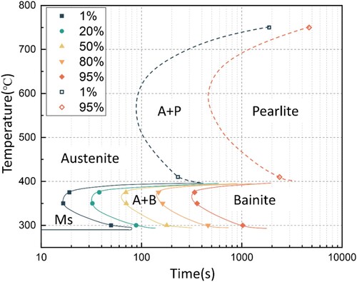
Isothermal transformation experiments are necessary to obtain the parameters for isothermal transformation because apart from the phase transformation modes associated with continuous cooling, the deposition process also involves the accumulation of heat. shows the experimental curves for the isothermal transformation of the deposited material. It can be observed that the bainite transformation occurs at a relatively fast rate in the low-temperature range.
Figure 10. Experimental results of isothermal transition of deposited material.
Based on the experimentally obtained phase transformation curve, the phase transformation model in DANTE Solutions was used to calculate the phase transformations during L-DED [Citation46, Citation47]. This model considers the diffusion-type phase and martensitic transformations, as discussed above. These two types of phase transformations are described by Eqs. Equation(3)(3)
(3) and Equation(4)
(4)
(4) , respectively:
(3)
(3)
(4)
(4) where Φd and Φm represent the volume fractions of individual diffusion phase and martensite, respectively; Φa represents the volume fraction of austenite; vd and vm are the phase transformation rate, while α1 and β1 are constants related to diffusion-type phase transformation; α2, β2, and φ are constants related to martensitic phase transformation.
Based on the established basic phase transformation kinetics model, this study developed a thermomechanical-phase transformation coupling model for single-layer deposition. The model is computed in parallel on an RWI 5.0 GHz 12-core processor with a wallclock time of 35.1 h for the temperature field model and 104.4 h for the phase transformation coupling model. The displacement curve at P0 position in the model is shown in . During cooling, the substrate and deposited layers underwent sequential transformations of bainite and martensite, resulting in volume expansion. These solid-state phase transformations contributed to the partial recovery of the deposited deformation during these stages. The martensitic phase transformation has a significant impact on the deformation recovery, causing a distinct inflection point in the deformation curve.
Figure 11. Displacement curve obtained using basic phase transformation model.
3.3. Deviation analysis between base model and experiments
To validate the description of phase transformation and deformation in the L-DED process using the basic phase transformation-coupled model, this study considered the physical process of three-layer laser deposition as a prototype. Both a thermomechanical-phase transformation coupled model and a thermomechanical coupled model were established. Repeated DIC experiments were carried out using the same process parameters to measure the historical deformation curves at the P0 point. presents a comparison of the repeated experimental data and model predictions.
Figure 12. Comparison of thermomechanical model and phase transformation coupling model with DIC results.
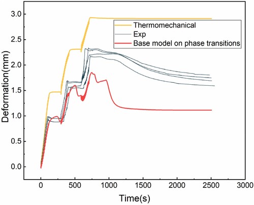
The experimental results during the cooling stage showed that neither the established basic phase transformation-coupled model nor the thermomechanical model could accurately describe the deformation history. The main drawback of the thermomechanical model is that it only considers thermal deformation during the cooling process, while neglecting the influence of volumetric phase transformation on deformation. Consequently, no deformation recovery was observed during the cooling stage. However, the basic phase transformation-coupled model predicts a deformation recovery that is much larger than the experimental deformation curve, leading to excessive recovery. In addition, the discrepancy between the predicted phase transition time and the experimental values arises due to inaccuracies in the setting of the phase transition temperature calculation. Precipitation during the deposition process is the factor that can influence carbon content of the material matrix and subsequently affect the phase transition temperature.
4. Analysis and modelling of phase-based characteristics
4.1. Effect of carbides on phase transitions
4.1.1. Carbon partitioning between carbides and matrix
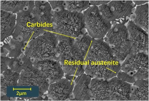
To clarify the deformation behaviour during the deposition cooling process, the cooling interval between layers was increased to 30 min. In addition, microscopic observations were conducted on the deposited layers at the end of deposition using a Phenom XL G2 instrument. The micrograph in is from the 15th pass of the first layer, etched for 5–8 s with 4% picric acid + C2H5OH as the etchant, and clearly shows the reticular precipitates and carbides. The carbon content in the model was determined based on the known total carbon contents of the deposited and substrate materials. However, the portion existing in the form of carbides must be excluded because of the carbon content involved in the phase transformation during the cooling process. Due to the high C content in T15, even with the presence of carbides, the carbon content within the grains is still high and the cooling process does not allow all the transformation to bainite and martensite, thus forming a certain amount of residual austenite.
Figure 13. Precipitate and carbides in the deposited layers.
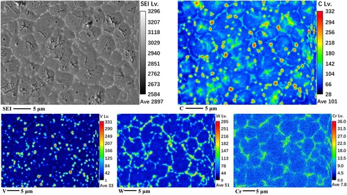
Solidification simulations using the Scheil model for the deposition material revealed that T15 high-speed steel underwent successive precipitation of austenite, M6C, MC, and M7C3 phases during the solidification process. Information on Scheil calculations has been presented in detail in our recent study [Citation48]. Furthermore, compositional analysis of the precipitates in the deposited layers was conducted using a JXA-8230 Electron Microprobe Analyzer (EPMA), which showed that the majority of the elements at the grain boundaries were W, V, and Cr, as shown in . Because was prepared for JXA-8230 EPMA elemental analysis using 4% HNO3 + C2H5OH for etching, the carbide features are not as obvious in the microscopic images as in .
Figure 14. EPMA mapping analysis of the deposited layers.
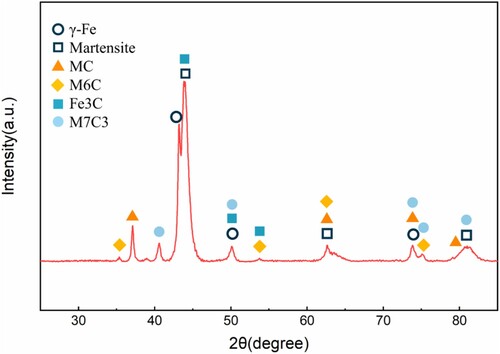
Based on the calculation of the carbide precipitation driving forces and the analysis of X-ray diffraction results (), it can be determined that the M6C, MC, and M7C3 phases correspond to Fe3W3C, VC, and Cr7C3, respectively. Using EPMA with a beam spot diameter of 1.5 μm, point scanning was performed inside the grains. The quantitative analysis results indicate that the carbon content within the deposition layer, excluding precipitates, is in the range of 1.22% to 1.29%. Although this is only a semi-quantitative result, it is indicative of the level of intra-grain carbon content which is significantly lower than the nominal carbon content of the alloy. Carbide precipitation occurred after austenite transformation and before bainite transformation. Therefore, the carbon content involved in subsequent displacive transformations in the model should be adjusted by subtracting the carbon content contributed by carbides, rather than considering the total carbon content of T15 high-speed steel. The intra-grain carbon content is the main determinant of bulk phase transitions, which are very difficult to determine accurately. The EPMA results were combined and an intermediate value between 1.2 and 1.3% was used for estimation.
Figure 15. XRD analysis results of the deposited layers.
4.1.2. Effect of carbide on martensitic phase transformation rate
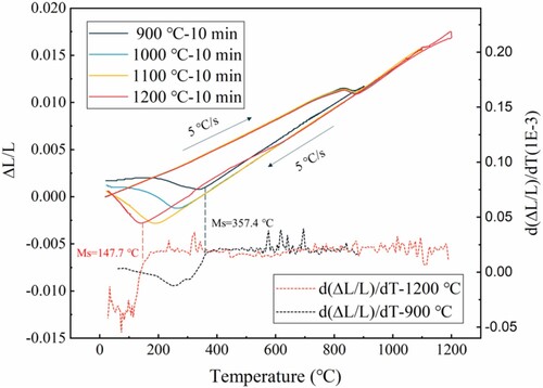
The precipitation of carbides not only affects the carbon content involved in displacive transformations but also significantly influences the transformation start temperature and rates of each phase. Continuous cooling experiments were conducted at four different holding temperatures to determine the variations in the transformation temperature and transformation rate. The heating and cooling rates for all experiments was 5 °C/s, and the holding time was 10 min. The corresponding dilatometry with its derivative curves are presented in . From the dilatometry curves of T15, it can be inferred that with the increase in holding temperature, the decomposition of carbides leads to a decrease in the martensite start temperature from the highest value of 357.4 °C to 147.7 °C. Additionally, as the holding temperature increases, the martensitic transformation rate also increases. The possible reason for this phenomenon is that at lower holding temperatures, carbides do not fully dissolve, resulting in lower carbon content in the matrix and less austenite being produced. This ultimately leads to lower martensitic transformation strain and transformation rate in the dilatometry test specimens.
Figure 16. Dilatometry with its derivative curves for different holding temperatures.
Owing to the high scanning speed of the laser, the cooling rate in the high-temperature stage (>900 °C) can reach up to 500 °C/s. Consequently, the dwell time in the high-temperature stage is relatively short, which is insufficient to allow for complete dissolution of carbides. Therefore, the transformation rate of martensite decreased in the presence of carbides. The model was constructed using the phase transformation rate at a holding temperature of 900 °C. The martensitic phase transformation rate during cooling for T15, denoted by parameter vm in EquationEq. (4)(4)
(4) was determined to be 0.94E-2. Ultimately, the model incorporates the two effects of carbides on the volume-phase transformations and obtains the deformation curves for the single-layer and multilayer L-DED processes, as shown in .
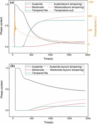
Figure 17. Prediction deformation considering the effect of carbide precipitation. (a) Single-layer deposition deformation and phase content. (b) Multilayer deposition deformation.
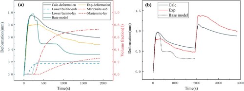
(a) shows the predicted deformation curve of a single-layer deposition process using the phase transformation-coupled model that accounts for carbide precipitation. Compared to the base model, the lower martensite start temperature results in a shift of the inflection point in the deformation curve. Additionally, the reduced martensitic phase transformation rate leads to a noticeable reduction in the deformation recovery rate. (b) demonstrates that the recovery stage of deformation in the two-layer deposition process is well characterized. Compared to the basic phase transformation model, the model that considers carbide precipitation provides deformation calculations that are closer to the experimental results.
4.2. Oxidation effect of multilayer deposition
During the L-DED process, an oxide layer inevitably forms on the deposited surface during long cooling. The electrical resistivity of a material is directly proportional to its oxide content [Citation45], as expressed in EquationEq. (5)(5)
(5) , where ox represents the oxidation efficiency during the L-DED process, and βox represents the oxide resistivity coefficient. According to the Bramson model, the electrical resistivity is an important material parameter that affects the energy absorptivity [Citation49], and its expression is given by EquationEq. (6)
(6)
(6) , where α represents the laser absorption coefficient of the deposition material, and λ represents the wavelength of the laser. Therefore, the effect of oxidation on energy absorptivity should be considered in the multilayer deposition model.
(5)
(5)
(6)
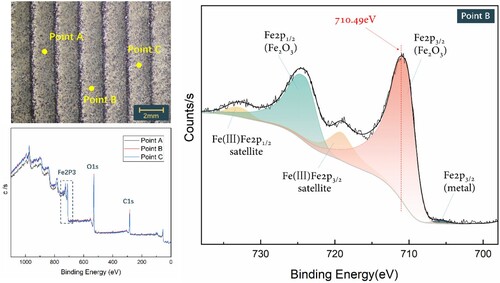
(6) X-ray photoelectron spectroscopy (XPS) was used to examine the deposited surface after cooling. Peak fitting of the Fe2p fine spectrum, it was found that the deposited surface was primarily composed of Fe2O3. The test results are presented in . Using the oxidation rate and Eqs. Equation(4)
(4)
(4) and Equation(5)
(5)
(5) , the model reevaluated the energy absorptivity of the system during multilayer deposition. The energy absorptivity of the two subsequent layers was 13.8% higher than that of the first layer.
Figure 18. Location and results of XPS measurements of the deposited surface.
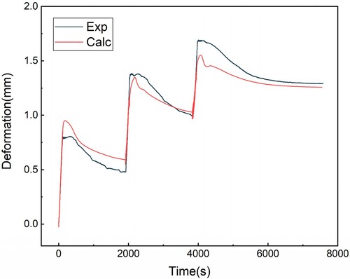
The absorptivity-corrected model calculated the deformation curve at the free end P0 of the substrate for the 3-layer L-DED process. The deformation curve of the coupled thermomechanical-phase transformation model considering the increased energy absorptivity is shown in . Compared to , the coupled model calculation results considering the surface oxidation effects reflect the actual deformation during deposition better.
Figure 19. Deformation curve at P0 calculated by the model considering oxidation.
4.3. Autotempering of quenching martensite
In the multilayer L-DED process, cyclic temperature variations of the material can induce tempering behaviour in the quenched martensite. This tempering behaviour alters the mechanical properties of martensite compared with its quenched state. Therefore, the model must consider the tempering behaviour of martensite and predict its effects. The calculation of tempered martensite is described by Eq (7):
(7)
(7) where Φt represent the volume fractions of tempered martensite phase; Φm represents the volume fraction of austenite; vt is the phase transformation rate, while α3 and β3 are constants related to tempered martensite phase transformation. In the DANTE software, α3 and β3 are respectively equal to 0.35 and 0.15. shows a comparison between the martensite transformation behaviour in the substrate and deposited layer during the L-DED process, along with the results obtained by incorporating the tempering model.
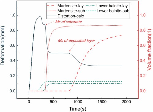
Figure 20. Martensite transformation behaviour during deposition and cooling processes. (a) Martensite transformation behaviour of the substrate; (b) Martensite transformation behaviour of the deposited layer.
The phase transformation process depicted in the model calculations revealed that the formation of tempered martensite primarily occurred during the cooling process rather than during the secondary heating by the laser. This was mainly because the initial temperature for tempering the martensite in the T15 high-speed steel was lower than the Ms point. Consequently, the martensite formed during cooling undergoes further transformation into tempered martensite, which is known as autotempering. During the multilayer L-DED process, although secondary heating may cause martensite to transform into tempered martensite, the temperature in the laser scanning area continues to rise above the austenitization temperature. Therefore, the tempered martensite forms primarily during the cooling process after the energy input of the system ceased.
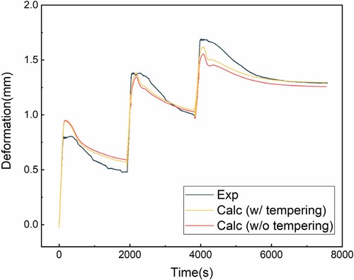
Martensite has a bct crystal structure with a linear coefficient of thermal expansion of 12.0 × 10⁻⁶/°C [Citation50]. Tempered martensite, consisting of a BCC structure and dispersed carbides, exhibits a thermal expansion coefficient between that of ferrite and cementite [Citation51], where the coefficients for ferrite and cementite are 11.5 × 10⁻⁶/°C [Citation52] and 12.5 × 10⁻⁶/°C [Citation53] respectively. Because of the similar thermal expansion coefficients of quenched martensite and tempered martensite, the tempering of martensite had no significant effect on the deformation during the L-DED process. The computed deformation curves are shown in . Considering the phase transformation process, incorporating martensite tempering resulted in a slight decrease in residual austenite. Consequently, the amount of warpage during the L-DED process was slightly higher in the model with tempering than without tempering.
Figure 21. Calculation of multilayer deposition deformation considering martensitic tempering.
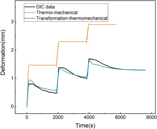
shows the substrate deformations calculated by the phase transformation coupling model and the thermomechanical model. The thermomechanical model, which does not consider phase transformation, fails to describe the substrate deformation recovery caused by the volumetric expansion due to phase transformation during the inter-layer cooling process. This ultimately leads to the deformation calculated by the thermomechanical model being significantly larger than the DIC value.
Figure 22. Comparison of deformation calculation between thermomechanical model and phase transformation coupling model.
5. Validation on microstructures
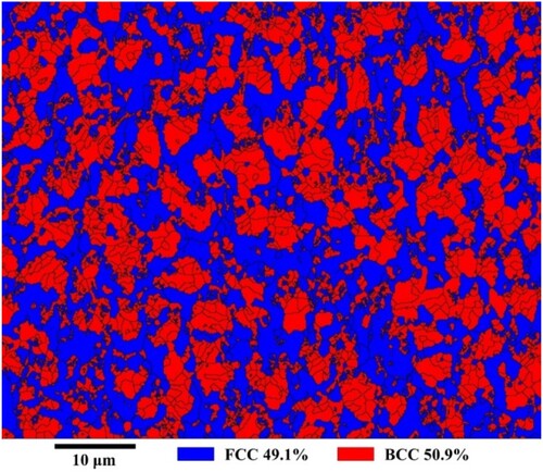
The model calculation results indicate that at the end of deposition there is an increasing trend in residual austenite in the direction perpendicular to the deposition path, as shown in (a). To validate the coupled model predictions of the phase content after deposition, qualitative XRD analysis was performed on the residual austenite after cooling. The XRD sample size is 6 mm × 6 mm and its measurement position is on the surface of the third layer, which is derived from the DIC deformation measurement sample. Sampling positions and measured peak intensities from repeated experiments are shown in (b). The XRD results show that the residual austenite peak intensity has an approximately increasing trend in the direction perpendicular to the laser deposition, confirming the agreement between the coupled model predictions of residual austenite phase content at the end of deposition and experimental observations. Quantitative testing of the phases in the second layer of the second pass of the deposited sample was carried out using an Oxford Symmetry EBSD instrument, as shown in . The results show that the measured residual austenite is 49.1% and the model prediction accuracy is 83.7%.
Figure 23. Comparison of residual austenite distribution calculated from the phase transformation coupling model and XRD results. (a) Simulated residual austenite distribution; (b) Variation of austenite peak intensity measured by XRD.
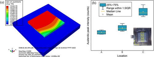
Figure 24. EBSD image of the second pass of the second layer deposited.
In addition to the differences in residual austenite distribution, the model calculations also show a correlation between the distribution of lower bainite and the order of deposition. The model predicts the distribution of lower bainite in the centre section of the deposition specimen at the end of cooling, as shown in . It can be observed that the volume fraction of lower bainite in the first-deposited region can reach 32.4%, while in the last-deposited region, the volume fraction of lower bainite is approximately 19.1%, and there is an overall decreasing trend in its distribution.
Figure 25. Comparison of lower bainite distribution between the prediction and experiments.
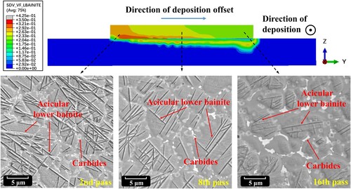
In order to validate the microstructural predictions of the model, observations of the microstructures were made at different locations on the three-layer deposition specimen. The experiment included SEM microstructural observations of the 2nd layer remelted zones in the 2nd, 8th and 16th passes depositions of the deposition specimen. Bainite was observed using 4% picric acid + C2H5OH etched continuously for 5 s. The microstructures of the different layers are shown in . Carbide precipitates at grain boundaries can be clearly observed in various regions. In addition, interlaced acicular lower bainite structures are visible.
The temperature variation curves at the central sections of the 2nd, 8th, and 16th passes in the deposition of the second layer as shown in . The temperature at the 2nd pass position is affected by the cyclic laser input, and the temperature cools down to a minimum of 190°C the second time it is heated above the Ac3 point. This temperature was above the Mf point and therefore only a partial martensitic phase transformation occurred. Subsequently, the quasi-isothermal transformation conditions were prolonged under laser heating, so that the lower bainite transformation predominated.
Figure 26. Temperature variation curves at the centre section of the 2nd, 8th and 16th passes of the second layer deposition process.
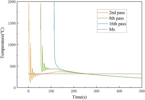
For the 8th pass, since the substrate had already been heated above the Ms point during deposition, the cooling between passes did not lower the temperature below the Ms point, thus it remained in a higher temperature range for an extended period. The process approximates an isothermal transformation process, so the phase transformation is dominated by the bainitic phase transformation. The final microstructural observations are consistent with the trends predicted by the phase transformation coupled model.
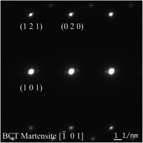
Martensite observations were made at the same location using 4% picric acid + C2H5OH etched etching for 15s. shows the model prediction of the martensite distribution on the cross section of the deposited sample at the end of cooling compared to the microscopic observation. It can be observed that the trend of martensite distribution in different regions of the deposition layer is opposite to that of bainite distribution. As the deposition progresses, the volume fraction of martensite increases from 5.7% in the first layer to 20.6% in the last layer. The calculated trend of tempered martensite from the model is consistent with the trend of martensite transformation. By prolonging the corrosion time using 4% nitric acid, martensite structures were observed within the grains in the centre of the plating layers. The microstructures at various positions in the plating cross section are shown in the lower part of . To determine the crystallographic structure of this feature, electron diffraction patterns were obtained by TEM from the characteristic regions of needle-shaped phase, and the test results are shown in . The diffraction pattern indices indicate that this portion of the microstructure is composed of BCT martensite.
Figure 27. Comparison of martensite distribution between the prediction and experiments.
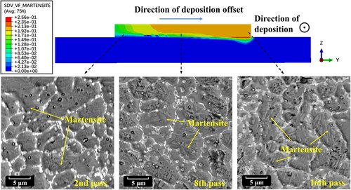
Figure 28. Electron diffraction pattern of the martensitic characterization site.
From , after the deposition of the 16th pass, the temperature quickly dropped below the Ms point under air cooling conditions due to the absence of laser influence. The experimental observations of the microstructure at different locations of the deposition show that the influence of subsequent deposition heat accumulation affects the earlier deposition layers, resulting in less observed martensite structures. In contrast, the deposition layers that experienced faster cooling rates toward the end of the deposition generated more martensite. For example, it takes 1.8 times longer for the 2nd pass to drop below the Ms point compared to the 16th pass. Due to the repeated heating of the initially deposited passes during the deposition process, they undergo a quasi-isothermal transformation process, which makes them more prone to bainite transformation with minimal martensite formation. From the microstructural observations, it can be concluded that the model predictions of the phase distribution are generally in agreement with the experimental results.
6. Comprehensive phase transformation during L-DED
The coupled model based on phase transformation established in this study explains the influence of phase transformation on deposition deformation, making it possible to understand the phase transformation during the deposition process through the deformation history. After considering the influence of certain phase transformation characteristics, it was found that the computed depositional deformation history was in better agreement with the experimental results than the base model. Therefore, it can be inferred that the phase transformation behaviour described in the computations reflects the actual phase transformation process more than that of the base model. This research methodology provides a new pathway for investigating the phase transformation history of the deposition process. The calculations show that the phase transformation behaviour of a complete deposition unit in L-DED consists of four main stages, as shown in .
Figure 29. Phase transformation at different moments of the L-DED and its effect on deformation.
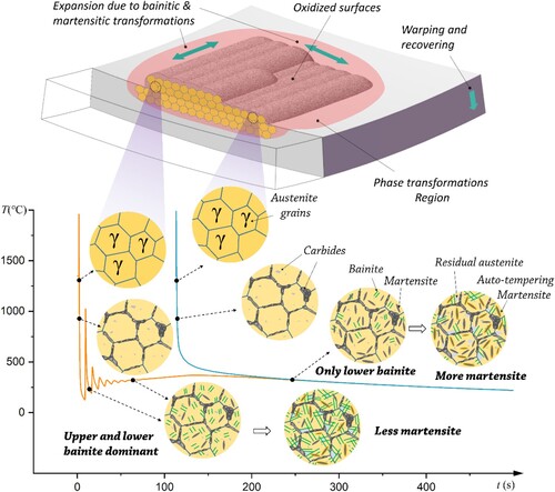
·During the deposition process, the continuous input of energy causes a transformation from ferrite/pearlite to austenite in the deposited layer and the adjacent region of the substrate. The addition of a high-temperature deposition material that undergoes successive cooling cycles results in maximum deformation of the part at the end of the thermal cycle.
·As the deposited layer begins to cool from the high-temperature austenitic state, carbide particles precipitate at the grain boundaries primarily in the form of MC and M6C phases. These carbides have a carbon content of approximately 0.35%, resulting in a reduction in the dispersed carbon in the matrix, which leads to an increase in the transformation temperature and a decrease in the transformation rate of the subsequent displacive transformations.
·Due to the characteristics of nonuniform heating and cooling, the earlier deposited passes undergo quasi-high-temperature transformations in subsequent thermal cycles. This results in the prevalence of upper and lower bainite transformations with fewer occurrences of martensitic transformations. In contrast, the layers deposited later primarily experience continuous cooling, leading to a higher occurrence of martensitic transformation and a lower occurrence of bainitic transformation. The sequential transformation of bainite and martensite results in material expansion, which contributes to the sustained recovery from deformation.
·As the cooling process continues to room temperature, martensite continues to form, accompanied by ongoing deformation recovery. Because the initialization temperature of martensite phase transition is lower than its tempering temperature, autotempering of the martensite occurs after its formation. The presence of carbides decreases the martensitic phase transformation rate, resulting in the retention of a certain amount of austenite in the deposited layer.
7. Conclusions
Detailed processes of specific phase transformations in L-DED are difficult to identify, which are related to the deformation history. In this study, a methodology was proposed to understand and identify the physics of phase transformations by iteratively comparing the deformation histories of measurements and simulations. Multilayer L-DED experiments were conducted using T15 high-speed steel as the deposited material and 4140 as the substrate. In situ DIC measurements were designed to determine the deformation history during deposition. The effects of carbon partitioning, martensitic phase transformation rate, surface oxidation, and autotempering were verified and modelled using base displacive transformations. The consistency of the deformation curves between the experiments and simulations confirms the reliability of the analysis. The comprehensive phase transformation during the L-DED process was as follows:
The precipitation of carbides (MC, M6C) led to a 0.35% reduction in the carbon content in the volumetric phase transformation compared to the nominal carbon content. Consequently, the martensite phase transition temperature increased by 208 °C compared to that of the base model.
A decrease in carbon content leads to a nonlinear relationship between martensitic transformation and temperature. Dilatometry tests show that a reduction in carbon content ultimately leads to a decrease in the martensitic phase transformation rate by approximately 73%. Based on this modified phase transformation coupling model, the deposition deformation curves also show good consistency.
In the multilayer L-DED process, experimental observations revealed the presence of iron oxide on the surface after deposition cooling, which increased the resistivity and energy absorptivity of the material. The calculations demonstrated that the subsequent layers, owing to surface oxidation, exhibited a 14% increase in energy absorptivity compared to the initial layer.
In the same deposited layer, the earlier deposited passes underwent quasi-high-temperature phase transformations in subsequent thermal cycles, primarily resulting in upper and lower bainite transformations with less martensite. In contrast, the later deposition passes primarily underwent continuous cooling, resulting in a higher occurrence of martensitic transformation and less bainite. Because the martensite phase transition temperature was higher than the tempering temperature, autotempering occurred during the cooling process, resulting in deposited layers containing six times more tempered martensite than quenched martensite.
Acknowledgements
We would like to express our gratitude to DANTE Solutions, Inc. and Dr. Zhichao(Charlie) Li for software support and model discussion.
Disclosure statement
No potential conflict of interest was reported by the author(s).
Data availability statement
The data that support the findings of this study are available from the corresponding author upon reasonable request.
Additional information
Funding
References
- Svetlizky D, Das M, Zheng B, et al. Directed energy deposition (DED) additive manufacturing: physical characteristics, defects, challenges and applications. Mater Today. 2021;49:271–295.
- Cheng J, Xing Y, Dong E, et al. An overview of laser metal deposition for cladding: defect formation mechanisms, defect suppression methods and performance improvements of laser-cladded layers. Materials (Basel). 2022;15(16):5522, doi:10.3390/ma15165522
- Shrestha S, Panakarajupally RP, Kannan M, et al. Analysis of microstructure and mechanical properties of additive repaired Ti–6Al–4V by direct energy deposition. Mater Sci Eng A. 2021;806:140604, doi:10.1016/j.msea.2020.140604
- Zheng D, Li R, Yuan T, et al. Microstructure and mechanical property of additively manufactured NiTi alloys: a comparison between selective laser melting and directed energy deposition. J Cent South Univ. 2021;28(4):1028–1042. doi:10.1007/s11771-021-4677-y
- Fallah V, Amoorezaei M, Provatas N, et al. Phase-field simulation of solidification morphology in laser powder deposition of Ti–Nb alloys. Acta Mater. 2012;60(4):1633–1646. doi:10.1016/j.actamat.2011.12.009
- Bidare P, Mehmeti A, Jiménez A, et al. High-density direct laser deposition (DLD) of CM247LC alloy: microstructure, porosity and cracks. Int J Adv Manuf Technol. 2022;120(11-12):8063–8074. doi:10.1007/s00170-022-09289-8
- Saboori A, Aversa A, Marchese G, et al. Microstructure and mechanical properties of AISI 316L produced by directed energy deposition-based additive manufacturing: a review. Appl Sci. 2020;10(9):3310.
- Joshi SS, Sharma S, Mazumder S, et al. Solidification and microstructure evolution in additively manufactured H13 steel via directed energy deposition: integrated experimental and computational approach. J Manuf Processes. 2021;68:852–866. doi:10.1016/j.jmapro.2021.06.009
- Edwards A, Weisz-Patrault D. É. charkaluk, analysis and fast modelling of microstructures in duplex stainless steel formed by directed energy deposition additive manufacturing. Addit Manuf. 2023;61:103300.
- Yang YP, Jamshidinia M, Boulware P, et al. Prediction of microstructure, residual stress, and deformation in laser powder bed fusion process. Comput Mech. 2017;61(5):599–615.
- Lin X, Cao Y, Wu X, et al. Microstructure and mechanical properties of laser forming repaired 17-4PH stainless steel. Mater Sci Eng A. 2012;553:80–88. doi:10.1016/j.msea.2012.05.095
- Silveira A, Fechte-Heinen R, Epp J. Microstructure evolution during laser-directed energy deposition of tool steel by In situ synchrotron X-ray diffraction. Addit Manuf. 2023;63:103408.
- Zhao C, Parab ND, Li X, et al. Critical instability at moving keyhole tip generates porosity in laser melting. Science. 2020;370(6520):1080), doi:10.1126/science.abd1587
- Gao W, Zhang Y, Ramanujan D, et al. The status, challenges, and future of additive manufacturing in engineering. Comput Aided Des. 2015;69:65–89. doi:10.1016/j.cad.2015.04.001
- Nie Z, Wang G, McGuffin-Cawley JD, et al. Experimental study and modeling of H13 steel deposition using laser hot-wire additive manufacturing. J Mater Process Technol. 2016;235:171–186. doi:10.1016/j.jmatprotec.2016.04.006
- Grujić K. A review of thermal spectral imaging methods for monitoring high-temperature molten material streams. Sensors. 2023;23(3):1130), doi:10.3390/s23031130
- Fetni S, Enrici TM, Niccolini T, et al. Thermal model for the directed energy deposition of composite coatings of 316L stainless steel enriched with tungsten carbides. Mater Des. 2021;204:109661.
- Wei S, Wang G, Wang L, et al. Characteristics of microstructure and stresses and their effects on interfacial fracture behavior for laser-deposited maraging steel. Mater Des. 2018;137:56–67.
- Li S, Kumar P, Chandra S, et al. Directed energy deposition of metals: processing, microstructures, and mechanical properties. Int Mater Rev. 2022;68(6):1–43.
- Chen W, Xu L, Han Y, et al. Control of residual stress in metal additive manufacturing by low-temperature solid-state phase transformation: an experimental and numerical study. Addit Manuf. 2021;42:102016.
- Xie D, Lv F, Liang H, et al. Towards a comprehensive understanding of distortion in additive manufacturing based on assumption of constraining force. Prototyping. 2021;16(sup1):S85–S97. doi:10.1080/17452759.2021.1881873
- Zhang Y, Wang G, Shi W, et al. Modeling and analysis of deformation for spiral bevel gear in die quenching based on the hardenability variation. J Mater Eng Perform. 2017;26:3034–3047. doi:10.1007/s11665-017-2729-0
- Weisz-Patrault D, Margerit P, Constantinescu A. Residual stresses in thin walled-structures manufactured by directed energy deposition: In-situ measurements, fast thermo-mechanical simulation and buckling. Addit Manuf. 2022;56:102903.
- Wang Q, Jia J, Zhao Y, et al. In situ measurement of full-field deformation for arc-based directed energy deposition via digital image correlation technology. Addit Manuf. 2023;72:103635.
- Bailey NS, Katinas C, Shin YC. Laser direct deposition of AISI H13 tool steel powder with numerical modeling of solid phase transformation, hardness, and residual stresses. J Mater Process Technol. 2017;247:223–233. doi:10.1016/j.jmatprotec.2017.04.020
- Weisz-Patrault D. Fast simulation of temperature and phase transitions in directed energy deposition additive manufacturing. Addit Manuf. 2020;31:100990.
- Yin H, Wang L, Felicelli SD. Comparison of two-dimensional and three-dimensional thermal models of the LENS® process. J Heat Transfer. 2008;130(10):102101), doi:10.1115/1.2953236
- Peyre P, Aubry P, Fabbro R, et al. Analytical and numerical modelling of the direct metal deposition laser process. J Phys D: Appl Phys. 2008;41(2):025403), doi:10.1088/0022-3727/41/2/025403
- Alimardani M, Toyserkani E, Huissoon JP. Three-dimensional numerical approach for geometrical prediction of multilayer laser solid freeform fabrication process. J Laser Appl. 2007;19(1):14–25. doi:10.2351/1.2402518
- Wen S, Shin YC. Comprehensive predictive modeling and parametric analysis of multitrack direct laser deposition processes. J Laser Appl. 2011;23(2):22003), doi:10.2351/1.3567962
- Papadakis L, Loizou A, Risse J, et al. A computational reduction model for appraising structural effects in selective laser melting manufacturing: a methodical model reduction proposed for time-efficient finite element analysis of larger components in selective laser melting. Virtual Phys Prototyping. 2014;9(1):17–25. doi:10.1080/17452759.2013.868005
- Mukherjee T, Manvatkar V, De A, et al. Mitigation of thermal distortion during additive manufacturing. Scr Mater. 2017;127:79–83.
- Cheng B, Shrestha S, Chou K. Stress and deformation evaluations of scanning strategy effect in selective laser melting. Addit Manuf. 2016;12:240–251.
- Yu J, Lin X, Ma L, et al. Influence of laser deposition patterns on part distortion, interior quality and mechanical properties by laser solid forming (LSF). Mater Sci Eng A. 2011;528(3):1094–1104. doi:10.1016/j.msea.2010.09.078
- Bhadeshia HKDH, Svensson LE, Gretoft B. A model for the development of microstructure in low-alloy steel (Fe-Mn-Si-C) weld deposits. Acta Metall. 1985;33(7):1271–1283. doi:10.1016/0001-6160(85)90238-X
- Bhadeshia H, Svensson L. Modelling the evolution of microstructure in steel weld metal. Math Modell Weld Phenom. 1993: 109–182.
- Papazoglou VJ, Masubuchi K. Numerical analysis of thermal stresses during welding including phase transformation effects. J Pressure Vessel Technol. 1982;104(3):198–203. doi:10.1115/1.3264204
- Taljat B, Radhakrishnan B, Zacharia T. Numerical analysis of GTA welding process with emphasis on post-solidification phase transformation effects on residual stresses. Mater Sci Eng A. 1998;246(1-2):45–54. doi:10.1016/S0921-5093(97)00729-6
- Zhang Y, Shi W, Yang L, et al. The effect of hardenability variation on phase transformation of spiral bevel gear in quenching process. J Mater Eng Perform. 2016;25:2727–2735. doi:10.1007/s11665-016-2125-1
- Plotkowski A, Saleeby K, Fancher CM, et al. Operando neutron diffraction reveals mechanisms for controlled strain evolution in 3D printing. Nat Commun. 2023;14(1):4950.
- Wei HL, Mukherjee T, Zhang W, et al. Mechanistic models for additive manufacturing of metallic components. Prog Mater Sci. 2021;116:100703.
- Liu L, Wang G, Ren K, et al. Marangoni flow patterns of molten pools in multi-pass laser cladding with added nano-CeO2. Addit Manuf. 2022;59:103156.
- Wei S, Wang G, Shin YC, et al. Comprehensive modeling of transport phenomena in laser hot-wire deposition process. Int J Heat Mass Transfer. 2018;125:1356–1368. doi:10.1016/j.ijheatmasstransfer.2018.04.164
- Hoadley AFA, Rappaz M. A thermal model of laser cladding by powder injection. Metall Trans B. 1992;23(5):631–642.
- Ren K, Di Y, Wang G, et al. Forward calculation model for utilization of energy and mass in laser-directed energy deposition. Addit Manuf. 2023;68:103512.
- Li Z. Innovative induction hardening process with pre-heating for improved fatigue performance of gear component. Gear Technol J Gear Manuf. 2014;31: 62–68.
- Li Z, Lynn Ferguson B, Sims J, et al. Sources of distortion study during quench hardening using computer modeling). Heat Treat 2017: Proceedings of the 29th ASM Heat Treating Society; 2017; Columbus, Ohio, USA, p. 350–356.
- Liu X, Wang G, Ren K, et al. On intertrack fluctuation of hardness and carbides in T15 steel laser cladding using thermodynamic calculation. J Mater Eng Perform. 2023;1–14.
- Bramson MA. Infrared radiation: a handbook for applications. New York: Plenum Press; 1968.
- Winchell P, Cohen M. The strength of martensite. Trans ASM. 1962;55:347–361.
- Callister WD, Rethwisch DG. Fundamentals of materials science and engineering. London: Wiley; 2000.
- Ruhl RC. Splat quenching of iron-carbon alloys. Trans Met Soc AIME. 1969;245:241–253.
- Powder Diffraction File. Astm card 6-0688. Philadelphia (PA): ASTM.
Appendix A.
Material parameters of the model
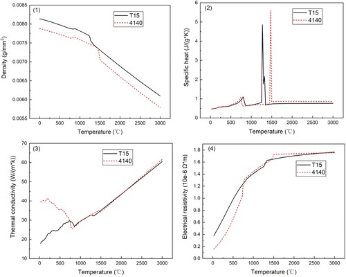
The thermophysical parameters of T15 and 4140 were determined by combining experimental measurements in the low-temperature range (25–900 °C) and calculations in the high-temperature range (900–3000 °C). Specific heat and thermal conductivity were measured using the laser flash method with a NETZSCHTM LFA457 instrument. The high-temperature parameters were calculated using the Thermo-Calc software. The variation curves of the thermal properties of T15 and 4140 materials are shown in Figure. A1.
Figure A1. Variation curve of thermophysical parameters of substrate and deposited material.
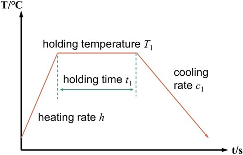
A Baehr-Thermo DIL 805A quench thermal expansion metre was selected for the temperature-strain test. The test material is obtained from the ingot formed by cooling the metal solution of T15 HSS powder prior to aerosolisation, and the size of the specimen for the thermal expansion test is Φ 4 × 10 mm, and the surface is machined by grinding with a roughness less than Ra1.6. The experiments are conducted to investigate the phase transformation of T15 HSS with different cooling rates, different holding temperatures and different holding times. The phase transformation point of T15 is obtained by continuous heating and cooling, and the experimental temperature profile is shown in Fig. A2. The T15 HSS specimen is inductively heated to the set holding temperature and then cooled linearly at a specified cooling rate, while the high-temperature strain gauges measure the axial strain of the cylindrical specimen in real time.
Figure A2. Schematic of temperature variation in continuous cooling experiment.
The tests were first carried out to investigate the phase transformation by setting different cooling rates. As the Ac1 and Ac3 of T15 HSS are 827°C and 854°C respectively, the initial holding temperature was set above the Ac3 point. A total of six groups of different cooling rates were set and the experimental parameters are shown in Table A.1.
Table A1. Parameter settings for continuous cooling experiments.
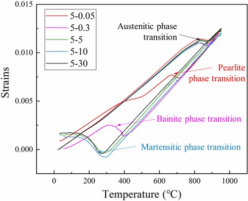
The results of the continuous cooling tests at different cooling rates are shown in Fig. A3. The temperature-strain curves of the cooling process show that three different phase transitions occur in T15 at different cooling rates. Among them, when the cooling rate is 0.05 °C/s, the material mainly undergoes pearlite transformation; when the cooling rate is 0.3∼1 °C/s, the T15 HSS mainly undergoes bainite transformation; and when the cooling rate is greater than 5 °C/s, it mainly undergoes martensitic transformation.
Figure A3. Dilatometry curves at different cooling rates.
Based on the experimental dilatometry curves of each phase, the kinetic parameters of the phase transition of the deposited material T15 in the base model were obtained by fitting with Eqs. (2) and (3), as shown in Table A.2.
Table A2. Kinetic parameters of the phase transformation of T15 in the base model.
AISI 4140 as a substrate material, the Dante software also contains the kinetic parameters of the phase transformation of each phase of the 41XX material at different carbon contents, which are listed in Table A.3.
Table A3. Kinetic parameters of phase transformation of AISI 41XX at different carbon contents.
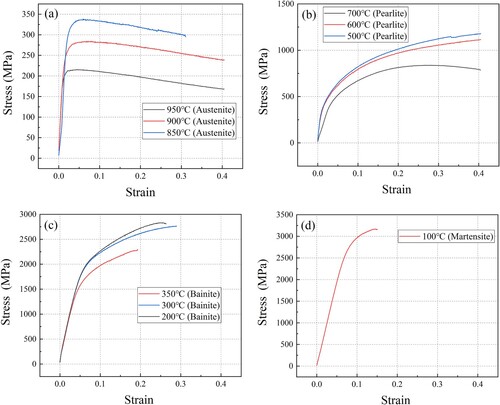
The stress-strain behaviour of the substrate and deposited materials is described using the Bammann – Chiesa – Johnson constitutive model in DANTE software. The model for the substrate material is based on data for 41XX series materials with 0.4% carbon content available in DANTE software. The model fitting data for the deposited materials in the DANTE software were obtained from the Gleeble thermal simulation test, and the stress-strain behaviour of each phase at different temperatures is shown in Fig. A4.
Figure A4. Stress-strain curves of single phase T15 HSS at different temperatures. (a) Temperature 950°C−850°C (Austenite); (b) Temperature 700°C−500°C (Pearlite); (c) Temperature 400°C−300°C (Bainite); (d) Temperature 100°C (Martensite).