
 ?Mathematical formulae have been encoded as MathML and are displayed in this HTML version using MathJax in order to improve their display. Uncheck the box to turn MathJax off. This feature requires Javascript. Click on a formula to zoom.
ABSTRACT
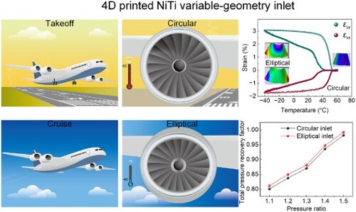
In modern aerospace engineering, the demand for innovative and adaptable solutions is paramount. This study focuses on enhancing aircraft engine components, specifically variable-geometry inlets, to meet evolving aviation technology requirements. We utilise custom Ni51Ti alloy powder to create 4D printed variable-geometry inlets. A comprehensive examination of thermal history and residual stress reveals differences in the behaviour of NiTi alloys at various points of the 4D printed inlet. After post-treatment, the printed inlet demonstrates stable two-way shape memory effects, undergoing adaptive deformation with temperature changes, mimicking the operational conditions of a commercial aircraft. Differential scanning calorimetry (DSC) and dynamic mechanical analysis (DMA) tests confirm that the 4D printed NiTi alloys maintain very stable phase transformation temperatures and two-way shape memory performance. Fluid dynamics simulations further reveal that the variable-geometry inlet design is potentially more efficient in certain operational scenarios with a total pressure recovery factor of 0.9919.
GRAPHICAL ABSTRACT
1. Introduction
The landscape of aerospace engineering is continually shaped by the demands of increasing efficiency, adaptability, and resilience of aircraft systems. A key focus area within this spectrum is the optimisation of engine air inlets, whose performance significantly influences the overall efficiency of the propulsion system [Citation1,Citation2]. Traditional designs of these inlets often face challenges under varying operating conditions, leading to the compromise of engine efficiency and power output.
Recently, there has been a growing interest in variable-geometry inlets that can adapt their shape according to different flight conditions, thereby optimising the airflow and enhancing engine performance [Citation3,Citation4]. These adaptive structures represent a step change in inlet design, offering the potential for increased efficiency across a broader range of operating conditions than is possible with conventional, static designs.
Shape memory alloys (SMAs), particularly those based on NiTi, with their ability to remember and return to their original shape upon exposure to appropriate stimuli such as temperature, are promising candidates for creating such adaptive structures [Citation3,Citation5–7]. A notable illustration of this was the Smart Aircraft and Marine Propulsion System Demonstration (SAMPSON) project, funded by the Defense Advanced Research Projects Agency [Citation8,Citation9]. In this initiative, SMA wire bundles replaced the conventional hydraulics control system to adjust the compression surface of the full-scale F-15 fighter engine inlet. Additionally, a SMA plate was used to regulate the external ramp shock of a supersonic inlet [Citation4]. They demonstrated that the newly proposed variable inlet can substantially improve the mass flow ratio at low Mach numbers. These applications underscore the proven applicability of NiTi SMAs in air intakes. Against this backdrop, the advent of 4D printing technology emerges as a transformative solution. By integrating time as an additional dimension, 4D printing unlocks the potential to streamline the complexity of mechanical control systems [Citation10–16], offering a pathway to more elegantly leverage the adaptive qualities of SMAs for variable-geometry inlets. Reflecting the simple geometry of existing NiTi alloys, most of which are wires or plates, the structural design of NiTi alloys has been limited. 4D printing technology can solve these limitations by enabling the creation of more complex and adaptive structures, thus expanding the potential applications of NiTi SMAs in advanced engineering solutions [Citation17].
However, the development of SMA-based deformable structures depends critically on the nuanced interplay of manufacturing, material processing, and subsequent performance [Citation18]. Laser-directed energy deposition (LDED)-based 4D printing, a technique that may introduce inhomogeneity and residual stresses due to cyclic reheating, non-equilibrium solidification and rapid cooling [Citation19–21], offers the distinct advantage of rapidly fabricating large-scale components compared to powder bed fusion-based additive manufacturing [Citation22]. While the impact of microstructural inhomogeneity and residual stresses on the mechanical properties of LDED manufactured alloys are well-documented [Citation23–25], their influence on the two-way shape memory properties of LDED NiTi alloys represents an under-explored area. Particularly intriguing is the impact of residual stresses on the precipitation of Ni4Ti3 during heat treatment, which can substantially affect the two-way shape memory properties of NiTi alloys.
Residual stresses have the potential to influence the nucleation and growth of Ni4Ti3 precipitates [Citation26], altering the microstructure and subsequent behaviour under two-way shape memory training. Such metastable microstructural features, often overlooked, could have profound implications for the functionality of the NiTi variable-geometry inlet, impacting its deformability and adaptability under varying temperature conditions.
In this study, we present an innovative approach to developing a NiTi-based variable-geometry inlet using 4D printing technology. Our research explores the challenges of inhomogeneity and residual stresses inherent in the fabrication process, which are pivotal for achieving the optimal two-way shape memory functionality. We rigorously validate the deformation capabilities and stabilities of the produced variable-geometry inlet through comprehensive experimental analysis and confirm its operational effectiveness with simulation models. This work demonstrates the potential of 4D printing to revolutionise the design and functionality of adaptive structures in aerospace applications.
2. Methods
Ni-rich Ni51Ti (at. %) powders (Figure S1, Table S1) were synthesised using the electrode induction-melting gas atomisation technique. To account for the evaporation of Ni during laser processing, we slightly increased the Ni content compared to conventional Ni-rich NiTi alloys. Our previous studies on NiTi alloys with this composition have demonstrated good mechanical properties and a wide range of adjustable phase transition temperatures [Citation26,Citation27]. The 4D printed NiTi alloy variable-geometry inlet was fabricated using laser-directed energy deposition (LDED) technology (RC-LDM8060, Zhongkeyuchen, China) on a substrate composed of Ni50Ti. After the 4D printing process, the inlet underwent annealing at 650°C for 2 hours and further stress-assisted ageing at 450°C for 2 hours both in air (Figure S2). Previous literature indicates that NiTi alloys exhibit minimal surface oxidation at these temperatures [Citation28,Citation29]. Electron back-scattered diffraction (EBSD), transmission electron microscope (TEM), differential scanning calorimetry (DSC) were used to analysed the misconstruction and phase transformation behaviour of the 4D printed NiTi alloy variable-geometry inlet. The stability of the two-way shape memory property was tested using dynamic mechanical analysis (DMA) in single cantilever mode. 3D digital image correlation technique (3D-DIC) was used to analyse the full-field displacements of the 4D printed NiTi alloy variable-geometry inlet during cooling and heating process.
The thermal history and residual stress of 4D printing process was simulated by Simufact-Welding software (Laser welding module). Thermophysical parameters and laser parameters for simulation are listed in Table S2 and Table S3, respectively. The performance of the 4D printed variable-geometry inlet was simulated using ANSYS Fluent (Figure S8). More details of the experimental and simulation procedures can be found in the supplementary materials.
3. Results and discussion
The environmental conditions that commercial aircraft encounter during takeoff and cruising phases are significantly different. The ability of the geometry of inlet to adapt to changes in environmental conditions can greatly enhance the engine efficiency [Citation30]. Inlets fabricated from NiTi shape memory alloys can undergo adaptive deformation between the takeoff and cruising phases. It is well-known that jet engines generate significant heat during operation due to fuel combustion. During takeoff (a), engines operate at a high-power setting to provide the necessary thrust for lift-off, which in turn leads to increased heat generation in and around the engine, including the inlet area. Besides, the aircraft speed is relatively slow. At this stage, the inlet needs to capture as much air as possible to provide the maximum mass flow rate, and therefore, the inlet shape is expected to be circular (b), corresponding to the austenite phase of the NiTi shape memory alloy (c). As the flight altitude increases, the aircraft enters its cruising state (d). At this point, due to the higher altitude, the environmental temperature drops to around −40°C [Citation31]. Since the aircraft speed during the cruising is approximately 0.8 Mach [Citation32], in a subsonic state, the required air flow rate for the engine decreases, and the compressibility of the air must also be considered. An elliptical-shaped inlet reduces the captured flow rate while improving the efficiency of airflow compression in front of the inlet. At this stage, the inlet shape is expected to be elliptical (e), corresponding to the R-phase of the NiTi shape memory alloy (f).
Figure 1. Application of 4D printing technology in the design of variable-geometry inlets for aero engines. (a)-(f) Civil aircraft at takeoff and cruise and the corresponding inlet shapes and the corresponding crystal structures of NiTi alloys. (a) Aircraft during the takeoff phase; (b) Circular design of the inlet during takeoff to accommodate low-speed, high-volume air intake with a working temperature of approximately 60°C; (c) State of the NiTi shape memory alloy material in the inlet duct during takeoff, in the austenite phase; (d) Aircraft during high-altitude cruising; (e) Elliptical design of the inlet during cruising to optimise aerodynamic performance in high-speed airflow with an ambient temperature of approximately −40°C; (f) State of the NiTi shape memory alloy material in the inlet duct during high-altitude cruising, in the R-phase state. (g)-(i) 4D printed inlet and finite element analysis (FEA) of the printing process. (g) 4D printed NiTi inlet after lathe milling process. (h) Residual stresses distribution of the as-printed inlet and 3 observation points marked as point A, point B and Point C in the 5th, 25th and 45th layer, respectively. (i) Thermal history of the three points. (J) Von Mises stress evolution of the three points.
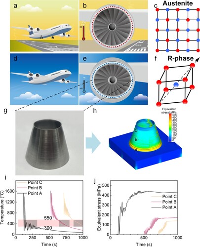
We employed custom Ni51Ti alloy powder for the preparation of 4D printed variable-geometry inlet. A conical inlet was formed using a spiral line trajectory, with a total of 50 printed layers. The 4D printed inlet is shown in g. Notably, post-printing, the sample underwent a simple lathe milling process to achieve a smooth surface. Given the high cooling rate and cyclic thermal history inherent to the LDED process, the inlet is expected to accumulate significant residual stress during formation [Citation20,Citation27,Citation33]. Our previous research [Citation27] has demonstrated that LDED-formed NiTi alloys exhibit good mechanical properties, including high strength (over 700 MPa) and good ductility (elongation over 6%).
The formation process was simulated using Simufact Welding software, as illustrated in (h-j). We selected observation points at the 5th layer (point A), 25th layer (point B), and 45th layer (point C), and recorded the temperature and Von Mises stress history at these points. The results, presented in i, show that the temperature fluctuation at point A is greater than at point B, and point B greater than point C. For Ni-rich NiTi alloys, the temperature range of 300–550°C [Citation34] represents a critical interval for aging processes. This specific temperature range has been highlighted in pink in i. The time each point remains within this range for Ni4Ti3 precipitation is longer for A than B, and B longer than C.
At the bottom of the inlet, where the circumferential radius is larger, the time interval between the heat source passing adjacent positions is longer, allowing the observation point more time to cool down. Furthermore, the proximity to the substrate also aids heat transfer at point A, enabling it to cool down to below 200°C during the initial LDED stage. However, as the formation process proceeds and the radius of the conical tube decreases, the time interval between the heat source passing adjacent positions at point B shortens, subjecting point B to more frequent reheating. The increase in distance from the substrate reduces the heat transfer efficiency at point B, maintaining it at a relatively high temperature during the initial stage.
The situation for point C is similar to point B, but the heating frequency increases further, and the distance from the substrate is even greater. This causes point C to remain above the precipitation temperature of Ni4Ti3 during the formation stage, and only begins to cool down after the formation process has completed.
As shown in j, the level of Von Mises stress is higher at point A than at B, and B than at C. This is due to differences in temperature gradients and cooling rates at each point. Generally, a larger thermal gradient and cooling rate will cause more pronounced shrinkage during material solidification [Citation20], thereby generating higher stress. For point A, the thermal gradient can reach 1.4 × 10⁵ K/m during the initial temperature cycling, while for points B and C, it is only 8.1 × 10⁴ K/m and 4.6 × 10⁴ K/m, respectively (Figure S3). Additionally, point A undergoes more thermal cycles during the preparation process, resulting in greater cumulative stress [Citation35]. The inlet shape samples are not suitable for residual stress testing. Therefore, we performed the residual stress test using the hole-drilling method on a 30 × 30 × 30 mm³ block sample prepared with the same laser parameters [Citation26]. The results are presented in Table S4. Literature [Citation36] indicates that the residual stress in LDED-formed NiTi alloys is uneven, similar to our simulation results.
The differences in thermal history and stress levels at each point suggest that the precipitation behaviour will vary at each point. This is particularly complex for Ni4Ti3, a lens-shaped precipitate phase with a clear orientation to the matrix [Citation7], the precipitation behaviour of which becomes quite complicated under the influence of internal stress [Citation26].
The NiTi alloy variable-geometry inlet, fabricated using a 4D printing process, exhibits distinct directional solidification structures. The inverse pole figure of the printed samples shown in a illustrates elongated grains in the building direction (BD), correlating with the significant temperature gradient of the LDED process. The remarkable temperature gradient and the substantial cooling rate generate significant residual stress. As seen from the kernel average misorientation map, numerous strain concentration regions are primarily distributed at small angle grain boundaries. The presence of many tangled dislocations in the printed samples (f) further confirms the significant residual stress within the samples. Moreover, b shows a roughly 19° deviation between the {100}B2 and the vertical direction, which is the building direction. We attribute this to the 15° angle formed between the generatrix of the conical tube and the BD (c).
Figure 2. Microstructural features and phase transformation behaviour of the 4D printed variable-geometry inlet. (a) Inverse pole figure map and kernel average misorientation map of the as-printed inlet. (b) {100}B2 pole figure of the area shown in (a). (c) 2D model of the inlet shows the 15° angle between generatrix of the conical tube and the building direction. (d) BF-STEM image and corresponding selective area diffraction pattern of the direct ageing sample. (e) Schematic diagram of the directionally distributed Ni4Ti3 under residual stresses. (f-h) BF-STEM images present the microstructure evolution of the 4D printed variable-geometry inlet. (i-k) Phase transformation behaviour evolution of the 4D printed variable-geometry inlet.
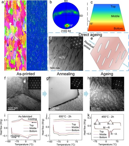
Because the printed samples contain significant residual stress, direct aging could lead to unexpected results. As shown in d, after aging at 500°C for 2 hours, the majority of Ni4Ti3 precipitate particles spontaneously arrange directionally. Due to the effect of residual stress, the long axis of the lens-shaped precipitate phase tends to be perpendicular to the direction of the maximum principal stress, schematically shown in e [Citation37]. It is well known that the coherent stress field generated by the directional arrangement of Ni4Ti3 is crucial for producing two-way shape memory effects. The coherent stress field formed by Ni4Ti3 will guide the formation of martensite, thus realising the memory of the low-temperature shape. Therefore, the directional distribution of Ni4Ti3 precipitate phase under residual stress will affect the regulation of subsequent two-way shape memory effects. Furthermore, different thermal histories at different locations during the printing process result in phase transformation temperatures that vary within the sample. As shown in i, the DSC curves of the bottom, middle, and top parts of the sample are noticeably different. The DSC curve of the bottom sample shows a wide phase transition peak with multiple phase transitions occurring, indicating significant compositional heterogeneity within the sample. The middle part of the sample exhibits a distinct R-phase transition, indicating that brief in-situ heat treatment is enough for Ni4Ti3 precipitation. Meanwhile, the phase transition peak of the top sample is the shortest, and the phase transformation temperature is the lowest, suggesting that the top sample is less affected by in-situ heat treatment. The uneven phase transformation temperatures in the 4D printed sample are evidently disadvantageous for the control of two-way shape memory effects.
We annealed the sample at 650°C for 2 hours, aiming to eliminate the heterogeneity caused by the in-situ heat treatment while also minimising the effect of oxidation. As shown in g, the dislocations within the sample have been eliminated. The DSC curves of the bottom, middle, and top parts of the sample after annealing are extremely similar (j), suggesting that the heterogeneity among the samples has been well mitigated. Following this, we aged the sample at 450°C for 2 hours. The aging temperatures and times were selected based on our previous research [Citation26] to maintain the R-phase transformation within the desired temperature range for our design.
The DSC curves of the samples from the three positions almost perfectly overlap (k). At room temperature, the sample is composed of B2 parent phase and R-phase (h), and the presence of Ni4Ti3 phase is confirmed through scanning transmission electron microscopy – energy dispersive spectroscopy (STEM-EDS) (Figure S4). The orientation relationship of [1 1 1]B2 // [1 1 1]Ni4Ti3 between B2 and Ni4Ti3 was confirmed by HRTEM, as shown in Figure S5.
During the cooling process, the main transformations are from austenite to R-phase and from R-phase to B19’ martensite. The R-phase transformation starts and ends at 38°C and 22°C, respectively, while the B19’ martensitic transformation starts and ends at −53°C and −70°C, respectively. In the take-off and ascent phase of a commercial aircraft, the air inlet operates at higher temperatures, allowing the material to remain in the B2 parent phase. When the aircraft reaches high-altitude cruising, the temperature decreases due to the elevation. At a cruising altitude of 8000 metres, the temperature is approximately −40°C. Under these working conditions, the variable-geometry inlet is in the R-phase state.
The results presented in demonstrate the robust phase transformation temperature stability and two-way shape memory performance of the LDED-formed NiTi alloy after post-treatment. The DSC curves for the NiTi alloy sample (a), cycled 20 times between −40°C and 60°C, exhibit excellent phase transition temperature stability. As shown in b, the strain-temperature curves obtained from DMA testing (Figure S6) over 10 cycles between −40°C and 65°C show remarkable reproducibility. The 1.6% two-way shape memory strain remains stable in single cantilever mode. The consistent overlap of the curves suggests that the NiTi alloy maintains its two-way shape memory effect even after repeated thermal cycling. The negligible change in strain-temperature behaviour over multiple cycles suggests that the material can repeatedly undergo significant deformation and recovery without degradation. These characteristices are vital for applications where materials are subjected to continuous thermal cycling, such as aircraft engine inlets that must adapt to different phases of flight.
Figure 3. DSC and DMA results illustrating the phase transformation temperature stability and two-way shape memory performance stability of the LDED-formed NiTi alloy after post-treatment, as well as HRTEM characterisation of the B2 and R-phase. (a) DSC curves for 20 cycles from −40°C to 60°C, showing excellent phase transformation temperature stability; (b) DMA strain-temperature curves for 10 cycles from −40°C to 65°C, demonstrating high reproducibility and good stability of the two-way shape memory effect. (c) BF-STEM image of the sample after annealing and stress-assisted aging heat treatment; (d) Selected area electron diffraction (SAED) pattern of the region in (c), showing the orientation relationship of [0 −1 1]B2//[0 −1 0]R; (e) Simulated SAED pattern of B2 and R-phase, indicating the presence of twins in the R-phase, with the twinning plane being {111}R; (f) HRTEM image of the same sample as in (c); (f1) FFT image of the red rectangular area in (f), indicating a single B2 phase; (f2) FFT image of the blue rectangular area in (f), showing a B2-R two-phase region; (f3) IFFT image of the (f1) region; (f4) IFFT image of the (f2) region, demonstrating the coherent interface between B2 and R-phase.
![Figure 3. DSC and DMA results illustrating the phase transformation temperature stability and two-way shape memory performance stability of the LDED-formed NiTi alloy after post-treatment, as well as HRTEM characterisation of the B2 and R-phase. (a) DSC curves for 20 cycles from −40°C to 60°C, showing excellent phase transformation temperature stability; (b) DMA strain-temperature curves for 10 cycles from −40°C to 65°C, demonstrating high reproducibility and good stability of the two-way shape memory effect. (c) BF-STEM image of the sample after annealing and stress-assisted aging heat treatment; (d) Selected area electron diffraction (SAED) pattern of the region in (c), showing the orientation relationship of [0 −1 1]B2//[0 −1 0]R; (e) Simulated SAED pattern of B2 and R-phase, indicating the presence of twins in the R-phase, with the twinning plane being {111}R; (f) HRTEM image of the same sample as in (c); (f1) FFT image of the red rectangular area in (f), indicating a single B2 phase; (f2) FFT image of the blue rectangular area in (f), showing a B2-R two-phase region; (f3) IFFT image of the (f1) region; (f4) IFFT image of the (f2) region, demonstrating the coherent interface between B2 and R-phase.](/cms/asset/e5ae38cf-33d1-4ee6-90cf-5e24436a366e/nvpp_a_2382166_f0003_oc.jpg)
c shows a well-defined microstructure of R-phase after annealing and stress-assisted aging heat treatment. The selected area electron diffraction pattern (d) confirms the orientation relationship [0 −1 1]B2 // [0 −1 0]R between the B2 and R-phase, indicative of coherent phase interfaces. The simulated diffraction pattern (e) reveals the presence of twins in the R-phase, with the twinning plane identified as {111}R [Citation7]. f further corroborates the microstructural details, showing areas of single B2 phase (red rectangular area) and B2-R-phase coexistence (blue rectangular area). The FFT and IFFT analyses (Figure f1-f4) of specific regions within the HRTEM image highlight the excellent coherency of the phase interfaces, crucial for the two-way shape memory effect of NiTi alloys.
The R-phase has a more favourable co-lattice relationship with the B2-phase than the B19'-phase does [Citation38,Citation39]. This compatibility significantly reduces the energy barrier for the phase transformation between B2 and R-phase, facilitating easier and more repeatable transformations [Citation40]. The better lattice matching minimises internal stress and strain during phase changes, which are often responsible for the introduction of defects. Moreover, The R-phase exhibits higher mobility of twins compared to the B19’ martensite [Citation38]. This higher twin mobility allows the R-phase to accommodate strain more effectively during phase transformations, thereby reducing the likelihood of defect formation. The ease with which twins can move within the R-phase matrix contributes to the smooth transition between phases, enhancing the overall durability and functional reliability during repeated cycling.
The modulation of the R-phase transformation through stress-assisted aging further stabilises the two-way shape memory properties. This specific aging process optimises the internal structure of the material, aligning the precipitates and internal stresses to favour the R-phase [Citation26,Citation37]. Compared to other training methods, stress-assisted aging ensures that the two-way shape memory effect is not only more stable but also more consistent in performance. This stability is crucial for ensuring that the material can reliably return to its original shape after deformation, an essential feature for adaptive applications such as aerospace components.
The findings suggest that LDED-formed NiTi alloys, with appropriate post-treatment, can achieve the desired thermal and mechanical properties for use in variable-geometry inlets. The stability of phase transformation temperatures and the robustness of the two-way shape memory effect ensure that these inlets can adapt to different operational conditions, improving engine efficiency and performance.
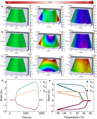
After two-way shape memory training, we verified the deformation capability of the 4D printed variable-geometry inlet within an environmental chamber (Supplementary Figure S7). The chamber temperature was first raised to 60°C and held for 5 min to stabilise the ambient temperature, and then cooled down to −40°C at a cooling rate of 4°C/min. As shown in (a-c)9, at 60°C, the inlet approximates a circular shape. This corresponds to the operational state of a commercial aircraft during takeoff and ascent from the ground or low altitudes. The inlet duct typically experiences temperatures higher than the ambient temperature due to heat exchange with the engine. Under these conditions, the incoming airflow speed is relatively slow, necessitating a larger capture area for the inlet. At −40°C, the variable-geometry inlet undergoes a significant deformation into an elliptical shape. This aligns with the operating state of a commercial aircraft during high-altitude cruising, such as when the environmental temperature at a flight altitude of 8000 metres is approximately −40°C [Citation31]. At this time, the aircraft flight speed is quite fast, nearing 0.8 Mach [Citation32]. Reducing the capture area of air inlet can increase the pressure of the airflow at the outlet of the air inlet, thereby enhancing engine efficiency [Citation41]. d and e present the strain-time and strain-temperature curve respectively at a specific area on the side of the 4D printed variable-geometry inlet. Taking the shape of the inlet at 60°C as the initial shape, the inlet expands along the axial direction as the temperature decreases. The onset temperature of the R-phase transition determined by the tangent method is 43°C, which is very close to the DSC test result (38°C). When the temperature drops to −40°C, the ϵyy reaches 3.1%. Subsequently, the inlet gradually returns to its original shape as the temperature increases. When reheated to 60°C, the inlet reverts to circular shape perfectly. The residual deformation is almost zero. The results indicate that the 4D printed variable-geometry inlet possesses a significant adaptive deformation effect.
Figure 4. Adaptive deformation capability of the 4D printed variable-geometry inlet. Displacement fields of the inlet with respect to the (a) U, (b) V and (c) W directions. The inlet was first heated up to 60°C and held for 5 min to stabilise the shape, and then cooled down to −40°C to have martensitic transformation. The inlet was then reheated to 60°C, where a martensitic reverse transformation occurs to revert to the high-temperature shape. (d) Strain (ϵyy, ϵxy, ϵxx) – time and (e) temperature curves.
Before diving into the performance analysis, it's crucial to clarify the rationale behind focusing exclusively on CFD simulations at an altitude of 8 km and a flight speed of Mach 0.8. Commercial aircraft spend the majority of their operational time cruising, with takeoff, climb, and landing phases comprising only a small portion of the overall flight duration [Citation32]. Therefore, enhancing inlet performance during cruise is of paramount importance. During takeoff and climb, the aircraft speed is relatively low. In these conditions, a circular inlet with a larger capture area is advantageous as it allows for greater air intake. Consequently, the circular inlet performs better under these low-speed conditions. However, at cruising speeds and higher altitudes, adaptability in inlet geometry can significantly improve fuel efficiency and engine performance.
Given these considerations, simulations were conducted to analyse the performance of circular and elliptical inlets under representative cruising conditions. The inlet static pressure ratio (SPR), defined as the ratio of the static pressure at the exit of the inlet to the static pressure at the entry of the inlet (ambient pressure), was examined. Additionally, the total pressure recovery factor (TPR), which measures the efficiency of the inlet in maintaining the total pressure of the incoming air, was also considered. The SPR and TPR are defined as follow:
(1)
(1) where
is the static pressure at the exit of the inlet, and
is the static pressure at the entry of the inlet.
(2)
(2) where
is the total pressure at the exit of the inlet, and
is the total pressure at the entry of the inlet.
a and b showcase the total pressure distribution maps for the circular and elliptical inlets at outlet static pressure ratios of 1.1, 1.3, and 1.5. These ratios were set to reflect different compressor operating conditions and to study their impact on inlet performance. At a lower outlet static pressure ratio (static pressure ratio = 1.1), the high total pressure zone is located in the centre of the section, while low-energy flow accumulates around the edges. As the outlet static pressure ratio increases (static pressure ratio = 1.3), the high total pressure zone concentrates more toward the middle, with the low total pressure zone clustering around the edges of the inlet. At an outlet static pressure ratio of 1.5, the total pressure distribution across the outlet section of the inlets becomes more uniform. This uniformity in pressure distribution indicates the absence of distinct high-pressure concentration areas typically seen at lower pressure ratios. The even distribution suggests that the flow within the inlet has stabilised and that dynamic effects influencing pressure variability have been effectively mitigated. This balanced distribution is beneficial for reducing structural stresses and enhancing the operational stability of the engine inlet system [Citation42].
Figure 5. Computational fluid dynamics simulation results of the 4D printed variable-geometry inlet. Total pressure distribution maps for the (a) circular and (b) elliptical inlets at outlet static pressure ratios of 1.1, 1.3, and 1.5 as typical examples; (c) Total pressure recovery factor as a function of outlet static pressure ratio.
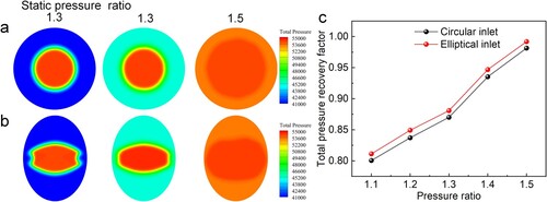
Furthermore, the total pressure recovery factor increases with higher outlet pressure ratios. A higher total pressure recovery factor signifies that the inlet is more efficient in converting dynamic pressure into static pressure with minimal losses. This efficiency is crucial for optimal engine performance, as it ensures that the maximum possible pressure is delivered to the compressor.
c plots the trend of total pressure recovery factors from static pressure ratios of 1.1 to 1.5, graphically depicting the efficiency increase for both inlet types. Combined with , we can see that initially, at a low outlet static pressure ratio, the total pressure recovery factor at the outlet section is 0.8005 for the circular inlet and 0.8112 for the elliptical inlet, with a Mach number at the isolator exit plane (Ma2) of 0.2479 and 0.2571, respectively. As the outlet static pressure ratio gradually increases, the total pressure recovery factor continues to rise, while the outlet Mach number steadily decreases. When the outlet static pressure ratio reaches 1.5, the total pressure recovery factor is 0.9814 for the circular inlet and 0.9919 for the elliptical inlet, and the Mach number drops to 0.0848 and 0.0865, respectively.
Table 1. The performance of 4D printed variable-geometry inlet at different outlet static pressure ratio (SPR).
These results confirm that both the circular and elliptical inlets achieve improved total pressure recovery factors as the outlet static pressure ratio increases. The superior performance of the elliptical inlet compared to the circular inlet under high-altitude cruising conditions can be hypothesised based on several key factors, for example, aerodynamic shape [Citation43] and flow control capability [Citation44]. These factors suggest that the elliptical inlet could achieve higher total pressure recovery factors and better overall performance and efficiency during high-altitude cruising. However, further detailed analysis and research are required to substantiate these hypotheses and fully understand the underlying mechanisms.
While this study focuses on a subsonic expanding intake, the innovative use of 4D printing technology for NiTi-based variable-geometry inlets shows great promise for supersonic applications. Supersonic inlets require advanced adaptability to handle higher thermal and mechanical stresses and complex airflow dynamics [Citation2,Citation4]. The stability of the R-phase transformation in NiTi alloys, combined with the design flexibility offered by 4D printing, can address these challenges. This technology enables the creation of more complex and efficient adaptive structures, potentially enhancing fuel efficiency and performance across various flight conditions. Future research should extend these principles to optimise inlets for the demanding environment of supersonic vehicles.
4. Conclusion
Our study highlights the potential of 4D printed NiTi alloy variable-geometry inlet in adapting to varying operational environments. The inherent properties of the NiTi alloy, when subjected to the LDED process, generate significant residual stress, influencing the precipitation behaviour of the Ni4Ti3 phase. Through post-treatment, we achieved two-way shape memory effects, allowing the inlet to adapt its shape according to environmental temperatures. This adaptive deformation capability, especially between the circular and elliptical shapes, offers potential performance enhancements for aircraft during different flight stages. The stability of the R-phase transformation is critical, with its superior co-lattice relationship with the B2 phase and high twin mobility, leading to fewer defects and greater stability during repeated transformations. The fluid dynamics simulations further substantiated the advantages of the elliptical design, especially during high-altitude cruising, as it produced higher total pressure recovery factors across a static pressure ratio range from 1.1 to 1.5, which could lead to improved engine efficiency. In summary, 4D printed NiTi alloy inlets represent a promising avenue for the aerospace industry, offering both material efficiency and adaptive capabilities to optimise engine performance.
Supplemental Material
Download MS Word (5.1 MB)Disclosure statement
No potential conflict of interest was reported by the author(s).
Data availability statement
The data that support the findings of this study are available from the corresponding author, [Ruidi Li], upon reasonable request.
Additional information
Funding
References
- Daynes S, Weaver PM. Stiffness tailoring using prestress in adaptive composite structures. Compos Struct. 2013;106:282–287. doi:10.1016/j.compstruct.2013.05.059
- Zuo F-Y, Mölder S. Hypersonic wavecatcher intakes and variable-geometry turbine based combined cycle engines. Prog Aerosp Sci. 2019;106:108–144. doi:10.1016/j.paerosci.2019.03.001
- Calkins FT, Mabe JH. Shape memory alloy based morphing aerostructures. J Mech Des. 2010;132(11):111012. doi:10.1115/1.4001119.
- Zhang Y, Tan H-J, Li J-F, et al. Ramp shock regulation of supersonic inlet with shape memory alloy plate. AIAA J. 2018;56(4):1696–1702. doi:10.2514/1.J056318
- Elahinia MH. Shape memory alloy actuators: design, fabrication, and experimental evaluation. Hoboken (NJ): John Wiley & Sons; 2016.
- Mehrpouya M, Cheraghi Bidsorkhi H. MEMS applications of NiTi based shape memory alloys: a review. Micro and Nanosystems. 2016;8(2):79–91.
- Otsuka K, Ren X. Physical metallurgy of Ti–Ni-based shape memory alloys. Prog Mater Sci. 2005;50(5):511–678. doi:10.1016/j.pmatsci.2004.10.001
- Pitt D, Dunne J, White E, et al. SAMPSON smart inlet SMA powered adaptive lip design and static test. Paper presented at the 19th AIAA Applied Aerodynamics Conference; 2001.
- Pitt D, Dunne J, White E. Design and test of a SMA powered adaptive aircraft inlet internal wall. Paper presented at the 43rd AIAA/ASME/ASCE/AHS/ASC Structures, Structural Dynamics, and Materials Conference; 2002.
- Chen G, Ma Y, Teng X, et al. Microstructure evolution and shape memory function mechanism of NiTi alloy by electron beam 4D printing. Appl Mater Today. 2023;31; doi:10.1016/j.apmt.2023.101749
- Isaac CW, Duddeck F. Recent progress in 4D printed energy-absorbing metamaterials and structures. Virtual Phys Prototyp. 2023;18(1):e2197436. doi:10.1080/17452759.2023.2197436
- Joshi S, Krishna Rawat CK, Rajamohan V, et al. 4D printing of materials for the future: opportunities and challenges. Appl Mater Today. 2020;18; doi:10.1016/j.apmt.2019.100490
- Khoo ZX, Teoh JEM, Liu Y, et al. 3D printing of smart materials: a review on recent progresses in 4D printing. Virtual Phys Prototyp. 2015;10(3):103–122. doi:10.1080/17452759.2015.1097054
- Leist SK, Zhou J. Current status of 4D printing technology and the potential of light-reactive smart materials as 4D printable materials. Virtual Phys Prototyp. 2016;11(4):249–262. doi:10.1080/17452759.2016.1198630
- Wang Y, Cui H, Esworthy T, et al. Emerging 4D printing strategies for next-generation tissue regeneration and medical devices. Adv Mater (Weinheim, Germany). 2022;34(20):2109198.
- Zheng D, Li R, Kang J, et al. Achieving superelastic shape recoverability in smart flexible CuAlMn metamaterials via 3D printing. Int J Mach Tools Manuf. 2024;195:104110. doi:10.1016/j.ijmachtools.2023.104110
- Poulton G. Aviation's material evolution. Airbus; 2017. Accessed 18 February 2017. https://www.airbus.com/en/newsroom/news/2017-02-aviations-material-evolution.
- Elahinia M, Moghaddam NS, Andani MT, et al. Fabrication of NiTi through additive manufacturing: A review. Prog Mater Sci. 2016;83:630–663. doi:10.1016/j.pmatsci.2016.08.001
- DebRoy T, Wei HL, Zuback JS, et al. Additive manufacturing of metallic components – Process, structure and properties. Prog Mater Sci. 2018;92:112–224. doi:10.1016/j.pmatsci.2017.10.001
- Svetlizky D, Das M, Zheng B, et al. Directed energy deposition (DED) additive manufacturing: physical characteristics, defects, challenges and applications. Mater Today. 2021;49:271–295. doi:10.1016/j.mattod.2021.03.020
- Xu R, Li R, Yuan T, et al. Towards the hydrogen pore in additively manufactured AlMgScZr alloy: influencing factors, formation kinetics mechanism. J Mater Sci Technol. 2024;199:125–144. doi:10.1016/j.jmst.2024.01.092
- Niu P, Li R, Gan K, et al. Manipulating stacking fault energy to achieve crack inhibition and superior strength–ductility synergy in an additively manufactured high-entropy alloy. Adv Mater (Weinheim, Germany). 2024:2310160. doi:10.1002/adma.202310160.
- Bian L, Thompson SM, Shamsaei N. Mechanical properties and microstructural features of direct laser-deposited Ti-6Al-4V. Jom. 2015;67:629–638. doi:10.1007/s11837-015-1308-9
- Rao PG, Rao, PS, Krishna AG. Review on residual stresses in welded joints prepared under the influence of mechanical vibrations. J Manuf Technol Res. 2014;6(1/2):33.
- Sticchi M, Schnubel D, Kashaev N, et al. Review of residual stress modification techniques for extending the fatigue life of metallic aircraft components. Appl Mech Rev. 2015;67(1):010801. doi:10.1115/1.4028160
- Kang J, Li R, Zheng D, et al. Unconventional precipitation and martensitic transformation behaviour of Ni-rich NiTi alloy fabricated via laser-directed energy deposition. Virtual Phys Prototyp. 2023;18(1). doi:10.1080/17452759.2023.2231415
- Luo MJ, Li R, Zheng D, et al. Formation mechanism of inherent spatial heterogeneity of microstructure and mechanical properties of NiTi SMA prepared by laser directed energy deposition. Int J Extreme Manuf. 2023;5(3). doi:10.1088/2631-7990/acd96f
- Dabbaghi H, Safaei K, Nematollahi M, et al. Additively manufactured NiTi and NiTiHf alloys: estimating service life in high-temperature oxidation. Materials. 2020;13(9):2104. doi:10.3390/ma13092104
- Xu CH, Ma XQ, Shi S-Q, et al. Oxidation behavior of TiNi shape memory alloy at 450–750 C. Mater Sci Eng A. 2004;371(1–2):45–50. doi:10.1016/S0921-5093(03)00287-9
- Oates GC. Aerothermodynamics of aircraft engine components. Reston (VA): AIAA; 1985.
- Bansemer AR, Heymsfield AJ, Willis PT. In situ measurements of particle size distributions in Hurricane Humberto. Preprints. Paper presented at the 25th Conference on Hurricanes and Tropical Meteorology, American Meteorological Society, San Diego, CA; 2002.
- Wu S-F, Grimble MJ, Breslin SG. Introduction to quantitative feedback theory for lateral robust flight control systems design. Control Eng Pract. 1998;6(7):805–828. doi:10.1016/S0967-0661(98)00053-7
- Mehrpouya M, Gisario A, Elahinia M. Laser welding of NiTi shape memory alloy: A review. J Manuf Process. 2018;31:162–186. doi:10.1016/j.jmapro.2017.11.011
- Zheng Y, Jiang F, Li L, et al. Effect of ageing treatment on the transformation behaviour of Ti–50.9at.% Ni alloy. Acta Mater. 2008;56(4):736–745. doi:10.1016/j.actamat.2007.10.020
- Li R, Wang G, Zhao X, et al. Effect of path strategy on residual stress and distortion in laser and cold metal transfer hybrid additive manufacturing. Add Manuf. 2021;46:102203. doi:10.1016/j.addma.2021.102203
- Zhang M, Duan Y, Fang X, et al. Tailoring the superelasticity of NiTi alloy fabricated by directed energy deposition through the variation of residual stress. Mater Des. 2022;224; doi:10.1016/j.matdes.2022.111311
- Khalil-Allafi J, Dlouhy A, Eggeler G. Ni4Ti3-precipitation during aging of NiTi shape memory alloys and its influence on martensitic phase transformations. Acta Mater. 2002;50(17):4255–4274. doi:10.1016/S1359-6454(02)00257-4
- Duerig TW, Bhattacharya K. The influence of the R-phase on the superelastic behavior of NiTi. Shape Memory Superelasticity. 2015;1:153–161. doi:10.1007/s40830-015-0013-4
- Zhu J, Wu H-H, Wu Y, et al. Influence of Ni4Ti3 precipitation on martensitic transformations in NiTi shape memory alloy: R-phase transformation. Acta Mater. 2021;207; doi:10.1016/j.actamat.2021.116665
- Chen Y, Li A, Ma Z, et al. Step-wise R-phase transformation rendering high-stability two-way shape memory effect of a NiTiFe-Nb nanowire composite. Acta Mater. 2021;219:117258. doi:10.1016/j.actamat.2021.117258
- Papagiannakis RG. Study of air inlet preheating and EGR impacts for improving the operation of compression ignition engine running under dual fuel mode. Energy Convers Manage. 2013;68:40–53. doi:10.1016/j.enconman.2012.12.019
- Farokhi S. Aircraft propulsion: cleaner, leaner, and greener. Hoboken (NJ): John Wiley & Sons; 2021.
- Lee J, Cho J. Effect of aspect ratio of elliptical inlet shape on performance of subsonic diffusing S-duct. J Mech Sci Technol. 2018;32:1153–1160. doi:10.1007/s12206-018-0218-5
- Hamstra JW, Miller DN, Truax PP, et al. Active inlet flow control technology demonstration. The Aeronautical J. 2000;104(1040):473–479. doi:10.1017/S0001924000091971