
 ?Mathematical formulae have been encoded as MathML and are displayed in this HTML version using MathJax in order to improve their display. Uncheck the box to turn MathJax off. This feature requires Javascript. Click on a formula to zoom.
ABSTRACT
This study explores the innovative use of 3D robotic spray for applying self-sensing cementitious coating, emphasising its potential for multifunctional smart concrete applications. The effects of spray parameters on the performance of self-sensing cementitious composites were investigated by systematically examining the impact of nozzle travel speed, air injection pressure, nozzle standoff distance, and spray direction on the self-sensing coating. In-depth analyses were conducted on mechanical strength, coating adhesion properties, and sensing performance. Micro-CT was performed to investigate the coating's inherent porosity. This study evaluated the sensing performance of the coatings by analysing their piezoresistive behaviour under cyclic compression and bending. Furthermore, it demonstrated the coating's capacity for real-time structural health monitoring by evaluating its performance under compressive and bending stresses until failure. This research underscores the significant impact of spray parameters on optimising the sensing capabilities of the self-sensing spray coating, highlighting its potential for advanced real-time structural health monitoring.
1. Introduction
3D concrete printing (3DCP) is a potentially transformative innovation in the field of construction engineering, which offers substantial potential to enhance productivity and safety [Citation1, Citation2]. Owing to its mechanisation and automation, 3DCP can significantly accelerate the construction process, reduce labour consumption and intensity, and minimise waste in construction. It enables the efficient execution of complex design with formwork-free construction, reducing the overall costs while improving construction efficiency [Citation3–5]. Despite its advantages, extrusion-based 3DCP faces significant challenges due to its layer-by-layer construction method and its restriction in vertical printing direction, limiting the wider applications of 3DCP technology [Citation6, Citation7]. 3D robotic spray has been developed, which integrates the advantages of shotcrete and 3DCP process. The high pressure incorporated in 3D robotic spray effectively enhances interlayer bonding strength between layers and offers excellent flexibility in multi-orientation deposition [Citation6]. It allows multi-directional construction and shows high precision in automated construction, which is ideally suitable for applying multifunctional smart concrete to existing structures.
Given the capability of robotic 3D spray technology to apply multifunctional smart concrete with high bonding strength and precision, it has a high potential for enhancing the functionality of existing infrastructure. Currently, the tremendous growth of infrastructure development has posed a significant challenge to the engineering community in ensuring structural safety. Concrete, as the most widely used construction material, has undergone rapid utilisation and has been utilised in a wide range of structures, such as high-rise buildings and offshore structures. However, the brittle nature of concrete structures makes them susceptible to cracking, which can result in in-depth erosion and damage that can pose serious hidden dangers, shorten the durability of the structures and even cause catastrophic failures [Citation8]. Therefore, continued monitoring and health assessment are of great significance for detecting and estimating the service conditions of concrete structures [Citation9]. Various types of sensors can be used to monitor real-time structural performance, including strain gauges, optical fibre sensors, piezoceramic sensors and other piezoelectric-based sensors [Citation10–13]. As one of them, self-sensing cementitious composites demonstrate both structural and sensing functionalities, exhibiting enhanced durability and high compatibility with existing structures, effectively overcoming the limitations of traditional sensors [Citation14]. The self-sensing cementitious composites can achieve sensing functionalities through the incorporation of conductive functional fillers, which form a conductive network within the cement matrix. The formed conductive network endows the cementitious composites with piezoresistive performance, which can be defined as the reversible change in electrical resistivity caused by the deformation of the conductive network when subjected to external loading [Citation14, Citation15]
Self-sensing cementitious composites can be applied in multiple application forms, including bulk, sandwich, sensor, and coating forms [Citation15]. Compared to the bulk form, coating, sandwich, and embedded forms allow targeted placement of the sensing composites within structural elements and broaden monitoring capabilities with reduced material costs [Citation16]. Particularly, as a coating, self-sensing cementitious composites can be readily applied to existing structures. Simultaneously, the self-sensing cementitious composite coating can serve as an additional protective and reinforcing layer, thereby offering dual functionalities [Citation17, Citation18]. However, despite these advantages, applying self-sensing cementitious composites, especially as coatings on existing structures, comes with its own challenges. These include achieving a uniform, cost-effective, large-scale application and operating in areas that are difficult for humans to work in, such as tunnels. Traditional application methods, like manual spraying, often fall short of providing consistent coverage and present issues related to labour intensity, productivity, and personnel safety, consequently compromising the composite's sensing performance. In addition to this, the quality of work performed during installation has a significant impact on the repeatability and robustness of sensors [Citation19].
Advancements in robotic technology, specifically 3D spraying technologies, provide a viable solution to these challenges [Citation7, Citation20]. The use of robotic 3D spray for the application of cementitious composite coating can ensure uniform distribution, thereby enhancing the overall sensing performance and protective capability. Furthermore, it can cover complex structural details with minimal human intervention, significantly reducing labour intensity and costs while improving personnel safety. 3D spray printing offers transformative applications in construction, enabling not only the creation of complex patterns onto vertical surfaces without formwork but also advanced multi functionalities such as temperature and strain monitoring and de-icing by resistance heating [Citation21, Citation22].
McAlorum et al. [Citation19] have demonstrated the feasibility of coating concrete substrates with self-sensing geopolymer material using a robotic spraying system. However, the absence of conductive functional filler in the developed sensing material leads to its susceptibility to the external environment, consequently limiting its application in large-scale structural monitoring. A previous study by the author successfully developed a self-sensing cementitious composite coating material suitable for robotic 3D spray applications. The sensing properties of the self-sensing cementitious composite materials have been optimised by employing a carbon fibre (CF) addition of 0.4 vol.% as the functional filler, which has the potential to enable effective and consistent monitoring of stress, strain, and deflection across structural elements [Citation23].
However, although the development of the self-sensing composite material has made significant progress, critical aspects such as the optimisation of spray parameters and their impact on the coating's adhesion and sensing performance were not thoroughly investigated. The importance of the spray parameters such as nozzle travel speed, spray pressure, nozzle distance and spray direction (horizontal spray, vertical spray and overhead spray) in achieving comprehensive sensor coverage and enhancing sensing performance remains unexplored. This study addresses these gaps by systematically examining these key spray parameters to optimise the performance of self-sensing spray coating.
2. Methodology
2.1. Mix design and preparation
2.1.1. Material and mix design
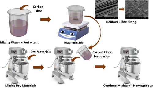
illustrates the mix design proportion of the developed robotic spray coating material used in this study. Ordinary Portland cement was used as the primary binder material. Silica fume, a supplementary cementitious material, was added to adjust the rheological properties of the mixture. Fly ash cenosphere is a hollow spherical lightweight aggregate sourced from fire power plants, which was incorporated to reduce density and enhance the distribution of sprayed materials against gravity-induced shear [Citation20]. CF was selected as the conductive filler due to its high conductivity and ease of dispersion, and it was added to the cementitious composite to achieve its conductive and piezoresistive characteristics [Citation15]. In general, CFs are sized during manufacturing with a viscous coating applied to facilitate handling. The existing sizing can lead to improper dispersion of the CFs, resulting in poor conductivity networks and the formation of defects within the cementitious composites. In order to eliminate the effects of sizing, water-soluble-sized CFs were used in this study, with the properties shown in .
Table 1. Mixing proportion of the robotic spray coating.
Table 2. Material properties of carbon fibre.
2.1.2. Preparation of spray materials
The mixture was prepared using a Hobart Mixer with adjustable rotation speed. To ensure a homogenous mixture and well-dispersion of conductive functional filler, the latter mixing method, illustrated in , was adopted for mixture preparation [Citation14]. The large surface areas of CFs can induce high Van der Waals force interaction between single fibres, requiring premixing to prevent agglomeration [Citation24]. A combination of chemical and mechanical dispersion methods was used by first dissolving CFs in an aqueous solution with a sufficient surfactant before mechanical dispersion. Polycarboxylate-based superplasticiser was selected as an effective surfactant for chemical dispersion, with magnetite dispersion applied to ensure fibres were dispersed properly into individual filaments instead of in bundle form. All dry materials were initially mixed in a Hobart mixer with a flat beater for 2 min at a mixing speed of 59 RPM, followed by adding the prepared functional filler suspension. Mixing continues at low speed (59 RPM) for 2 min, then at medium speed (107 RPM) for another 3 min or until homogeneity is achieved. Once mixed, the fresh mixture underwent rheological tests to analyse its static yield stress, dynamic yield stress, and plastic viscosity [Citation23]. The test confirmed that the developed mixture could be consistently sprayed and was subsequently transferred into the pumping system for robotic spray printing.
Figure 1. Schematic drawing of the latter mixing method
2.2. Robotic spray
2.2.1. Setup of spray printing
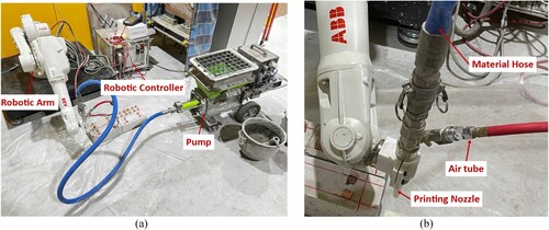
illustrates the robotic spray printing setup, including a detailed specification of the spray printing nozzle. The setup employs an ABB-IRB 1600 six-axis robotic arm with a reach of 1.45 meters to ensure precise control of the nozzle orientation and position during the spray printing process. During the spray printing, the prepared self-sensing cementitious mortar mixture was first poured into the material feeder and subsequently delivered through the material delivery hose by a rotor-stator Pictor pump (MAI-2 Lyra). The material delivery hose connected to the pump and the spray nozzle was 2.5 m in length and had an inner diameter of 25.4 mm. The spray nozzle tip, with a length of 50 mm and an inner diameter of 18 mm, was mounted at the end of the robotic arm. Concurrently, compressed air was injected into the mixture via the air tube connected to the nozzle, helping the material to be sprayed onto the substrate. Throughout this process, the spray printing nozzle moved along a predetermined path at a controlled speed to ensure uniform spray printing results. The thickness of the sprayed coating is controlled to range from 3-5 mm, which is related to the spray parameters.
Figure 2. Setup of the robotic spray: (a) spray printing system and (b) details of the spray nozzle.
2.2.2. Design of spray parameters
The quality and functionality performance of the self-sensing cementitious coating can be greatly influenced by the spray parameters [Citation25]. Four key parameters, each with three distinct values selected, have been identified and investigated in this study in order to gain a comprehensive understanding of the effects of spray parameters. summarises the chosen parameter values alongside with their anticipated influence on the coating.
Table 3. Designed parameters and values evaluated for spray printing.
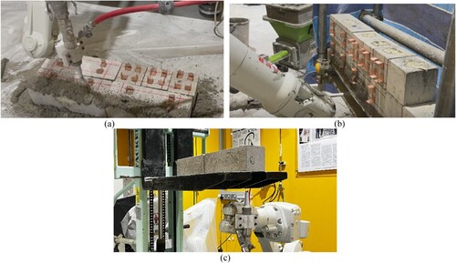
The nozzle travel speed is anticipated to be the primary determinant of the coating thickness, which ranges from 3-5 mm. It is expected that a higher travel speed will result in a thinner coating. However, excessive speed may disrupt the continuity of the spray, resulting in poor coverage and compromised uniformity of the coating. Air injection pressure can have multiple effects on the coating, influencing attributes such as surface quality and uniformity, porosity and bond strength. An elevated spray pressure typically results in a denser coating and can potentially enhance bonding strength. However, excessive pressure can displace material, leading to poor uniformity of the coating. 50 , 75 , and 100 mm were chosen to be the nozzle standoff distance used in this study, as it can affect the coating uniformity, a closer nozzle standoff distance can lead to localised concentration and limit the overspread of the spray, potentially resulting in uneven coating [Citation6]. Spray direction was studied, considering vertical, horizontal, and overhead sprays (). The chosen direction influences the bonding strength of the coating, with gravitational effects particularly impacting horizontal and overhead applications. Studying these three directions is necessary to ensure that every geometric aspect of a structure, regardless of its orientation, can be effectively coated.
Figure 3. Schematic of robotic spray in 3 directions:(a) vertical, (b) horizontal and (c) overhead.
2.2.3. Sample preparation
Concrete blocks, cast in the dimensions of 100 × 100 × 300 mm beams and 100 mm cubes, were utilised as the substrate for spray application. The electrodes were attached to the precast concrete blocks at the designed locations prior to the spray printing to achieve an enhanced electrode-coating bond. Distinct parameters, including nozzle travel speed, air injection pressure, nozzle standoff distance and spray direction, were varied methodically to analyse their influence on the coating performance. The specifics of each specimen group are summarised in . After the coatings were applied onto the prefabricated concrete blocks, all prepared specimens were covered with preservative plastic films, and water was regularly sprayed onto the samples to ensure proper curing until the test age of 28 days.
Table 4. Detailed spray application parameters of prepared concrete specimens.
2.3. Testing methods
2.3.1. Mechanical properties
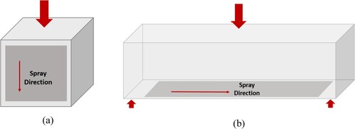
Compressive and flexural strength were evaluated to study the potential enhancement in mechanical properties provided by the coating on concrete substrate. Three samples from each testing group were tested to ensure consistent and reliable results. The compression tests were conducted on 100 mm cubes with the loading direction parallel to the spray direction. 100 × 100 × 300 mm beams were undertaken three-point bending tests to determine the flexural strength (). For comparison, three uncoated samples, both cubes and beams, were tested as reference benchmarks to understand the reinforcing effect of the coating on the inherent mechanical properties of concrete blocks.
Figure 4. Schematic of compression and 3-point bending tests.
2.3.2. Split tensile test
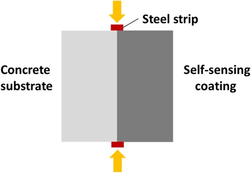
The splitting tensile test was conducted in accordance with ASTM C496 [Citation26] to evaluate the bond strength between the concrete substrate and coating. The test employed scaled-down, cubic samples to align with the dimension of 3D sprayed coating [Citation27, Citation28]. As shown in , two steel strips were placed at the top and bottom of the specimen to ensure a consistent and uniform distribution of tension throughout the samples during testing. The split tensile strength of the samples can be defined as (1):
(1)
(1) Where Pu is the ultimate load, B is the specimen thickness, and D is the specimen width. Despite the fact that cubic specimens were employed in this study instead of cylinders, the same expression remains valid, as confirmed by the established findings that stress distribution is similar in both geometries at the centre plane [Citation29].
Figure 5. Schematic diagram of split tensile test for bond strength measurement.
The specimens for the split tensile tests were prepared by cutting from larger coated specimens, which were cured for 28 days under the same conditions as the samples designed for mechanical and electrical measurement. To ensure accurate bond strength measurements, these specimens remained intact and have not been subjected to any loading prior to cutting. Given the variations in the coating thickness, which ranged between 3-5 mm, precise cutting was made by a diamond cutter to ensure that the interlayer between the coating and substrate was centrally loaded in each sample, thus avoiding eccentric loading and ensuring the reliability of the test results.
2.3.3. Micro-CT analysis
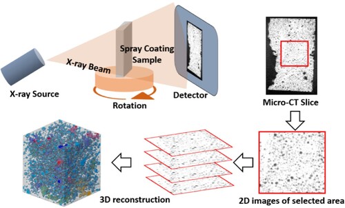
To conduct a detailed analysis of porosity and to explore its impact on the bonding properties of the coatings, micro-computed tomography (micro-CT) scans were performed [Citation30]. Three specimens from each test group were selected for CT scan analysis, which was conducted using a Bruker Skyscan-1173 scanner. The scanning parameters were set to achieve a voxel dimension of 48 µm, a voltage of 70 kV and a current of 160 µA. From each prepared sample, a selected area with a dimension of 5 mm × 5 mm was extracted from the interlayer zone of the coating to characterise its porosity. The scanned images of the selected zone were subsequently reconstructed using the digital image processing (DIP) software Avizo3D. This involved processing over 800 extracted Y-Z plane CT slices per specimen, enabling the reconstruction of the pore distribution and the calculation of the overall porosity ().
Figure 6. Schematic of Micro-CT scanning and reconstruction of 3D images.
2.3.4. Analysis of self-sensing performance
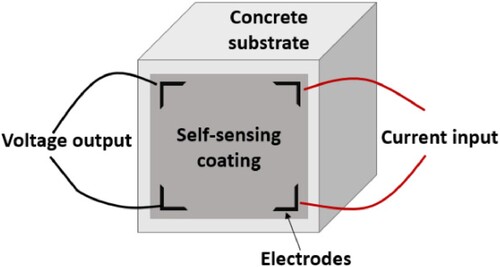
Piezoresistivity tests for coated specimens under mechanical strain were conducted to evaluate the self-sensing performance of the coating. A 4-electrode Vander Pauw configuration, as demonstrated in , was utilised to ensure accurate resistance readings, as it can minimise the influence of contact resistance and reduce the interfacial stresses between the electrodes and the self-sensing coating during curing [Citation19].
Figure 7. Schematic drawing of 4-electrode Vander Pauw configuration for piezoresistivity measurement.
Prior to testing, all samples underwent a drying process in an oven at 60°C for three days to mitigate the polarisation effect induced by the moisture. This polarisation effect is caused by the use of direct current during testing. There are two common methods to eliminate this effect: one is conducting a drying process to evaporate the pore solution; another is applying the current for an extended period until the specimens are fully polarised. In practical applications, the alternative current is recommended, as it does not lead to the polarisation issues associated with direct current due to its periodically reversing direction. The coated 100 mm cubes were subjected to cyclic compression by applying a force of 4 MPa per cycle over ten cycles. Concurrently, the 300 mm coated beams were subjected to cyclic bending, each with a magnitude of 1.45 MPa. The applied loads were selected to ensure that the examinations of the piezoresistivity of the developed self-sensing coating were conducted within the elastic range. The control of the loading conditions is crucial to preventing any damage that could lead to irreversible changes in the electrical resistivity of the sensing materials. This irreversible change could compromise both the stability and repeatability of the sensing materials, resulting in inaccurate test results. Both of cyclic compression and cyclic bending were applied by a universal testing machine Instron 960. Throughout these tests, variations in electrical resistance were continuously recorded with a Keithley 2100 multimeter, with a built-in auto range selection function. The fractional change in resistivity (FCR) of each specimen was calculated using Eq. (2).
(2)
(2) Where
is the measured electrical resistivity and
is the initial electrical resistivity.
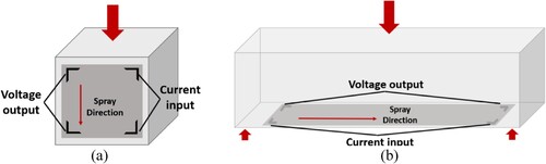
illustrates a schematic of the electrodes and sample layouts adopted for these tests. For cubic samples, the coated surface faced frontward, which experienced compression. For beams, the coated surface was positioned on the underside of the beam, which is the area predominantly under tension during bending. In both layouts, the electrode orientation was aligned parallel to the strain changes, ensuring maximum sensitivity in response to substrate strain variations. Beyond the cyclic tests, a load-to-failure approach was employed for both cubes and beams, aiming to observe the resistivity changes up to the structural failure point under both compressive and flexural scenarios.
Figure 8. Schematic of electrode configuration of samples under (a) compression and (b) bending with measurement orientation parallel to strain variation.
3. Results and discussions
3.1. Mechanical performance
The compressive and flexural strength of coated specimens, subjected to a variety of spray parameters, were thoroughly examined, and the results were analysed and presented in . As reference values, the strength of the uncoated concrete substrate, as well as the coating itself, are indicated in the figure.
Figure 9. (a) Compressive and (b) Flexural strength of samples with sprayed coating.
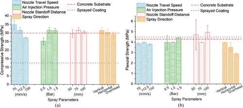
(a) indicates that the application of the coating has a negligible impact on the strength of the concrete substrate, with the test results closely aligned with the reference value of the uncoated specimens. Although variations in the compressive strength can be noted, these discrepancies are more likely attributed to the variability of concrete substrates rather than the effect of the spray process. An exception could be observed for samples coated at a nozzle travel speed of 75 mm/s, which exhibit an increase in compressive strength. This enhancement could be related to the development of a thicker coating layer. This highlights the capability of the spray coating in terms of improving the structural strength, which is particularly beneficial for those with existing cracks.
(b) suggests that the flexural strength of the sprayed concrete coating is comparable to that of the concrete substrate. It is noteworthy that when the coating was applied under increased pressure or from a greater distance, a slight enhancement in flexural strength was observed, which indicates the potential of denser coating to improve the flexural strength of the concrete substrate. Conversely, when the coating was applied in orientations such as horizontal or overhead directions, a contrasting behaviour was noted. Under these conditions, the sprayed coating is weaker in strength, and the overall reduced flexural strength could be attributed to the cracking of the coating. These cracks within the coating may lead to stress concentration, thereby accelerating the early failure of the concrete substrate.
3.2. Bond strength and adhesion of the coating
(a) shows the results of the interfacial split tensile strength tests, which indicate the bonding strength and adhesion characteristics of the spray coating to the substrate. The bonding strength is related not solely to the properties of the material itself but is also highly significantly impacted by external factors [Citation31]. According to the results, most of the spray parameters tested are significantly correlated with the strength of the interlayer bonding. However, an exception could be observed with nozzle travel speed, which does not exhibit a consistent trend in influencing bonding strength. As expected, the bonding strength of the coating increases with an increase in air injection pressure, underscoring the direct relationship between pressure and bonding strength. A pressure setting of 1.5 Bar was found to be effective, which maintained a balance between improving bond strength and preventing materials from being displaced [Citation23, Citation32]. In contrast, coatings applied in the overhead direction displayed the lowest bonding strength, as gravitational forces may lead to a reduction in adhesion, preventing an effective bond between the substrate and applied coating.
Figure 10. Assessment of correlation between coating adhesion and spray parameter: (a) bonding strength measurements and (b) microscopic images of bonding zones.
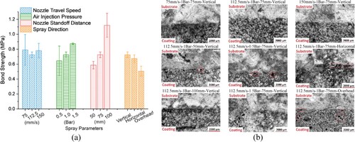
In addition to these observations, a previously unexpected correlation between nozzle standoff distance and interlayer bonding strength was identified. It was found that an increase in nozzle standoff distance led to enhanced bonding. It is possible to explain this phenomenon by considering how nozzle standoff distance influences spray coverage. A larger distance between the nozzle and substrate results in a wider spray patch, leading to overlap between successive spray profiles. Such overlapping, particularly when applying subsequent layers, creates a compacting effect on earlier layers, resulting in a denser interlayer structure that potentially enhances bonding strength.
In addition to the quantitative analysis of the bond strength, high-resolution microscope images were used to visually assess the bonding zone of the samples, providing a visual confirmation of the coating's microstructural integrity and adhesion property. An optical high-resolution microscope (SZX7, Olympus Corporation) equipped with an ACH-1X achromatic objective, a U-CMAD3 camera adapter, and an SC30 colour camera was used to examine the exposed normal cross-sections of cut samples. (b) demonstrates the quality of the bonding between the sprayed coating and the concrete substrate, which is consistent with the findings obtained from the bonding strength tests. It is evident that coatings sprayed at higher air injection pressures (1.5 Bar) or at longer nozzle standoff distance (100 mm) exhibit superior bonding properties. Conversely, when the coating is applied at a lower pressure (0.5 Bar) or in an overhead direction, air voids can be observed between the coating and the substrate. This consistency in observation across both visual and quantitative analysis further validates the relationship between the spray parameters and the adhesive effectiveness of the coating.
demonstrates the porosity results of the selected samples obtained from the CT scanning. Coating subjected to lower air injection pressure exhibited higher porosity, likely due to the reduced impact force of the spray, consequently leading to less compacted deposition of materials [Citation33]. Conversely, the coating applied in the vertical direction or with extended nozzle standoff distance showed a decrease in porosity. This reduction could be attributed to the compaction force of gravity or effective layer stacking during spray.
Figure 11. Comparative analysis of spray coating porosity across different spray parameters.
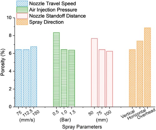
It was observed that samples exhibiting higher bonding strengths typically possessed lower porosity, which proven that the inherent porosity of the coating materials may also be a significant factor influencing bond strength. The reduced porosity appears to enhance bond strength through two primary mechanisms [Citation34, Citation35]. Firstly, it increases the contact area between the coating and substrate, consequently strengthening the mechanical interlocking and enhancing the adhesion [Citation36]. Studies have established a positive correlation between the shrinkage in cementitious materials and their porosity, as well as the pore size [Citation26, Citation27]. The reduced pore size and porosity can lead to a reduction of shrinkage in the coating, which prevents the formation of cracks and gaps at the interface that could compromise the bond [Citation37].
The pore size distribution of internal pores, together with the 3D reconstructed images of pore distribution in specimens, illustrated in , further demonstrates the impact of spray parameters on the coating porosity. Among all tested specimens, the pores smaller than 0.002 mm3 account for more than 50% of the total pore count. The pore size distribution curve across all test groups displays a pronounced negative exponential trend, indicating a decrease in the percentage of pores with the increasing pore size.
Figure 12. Pore size distribution of the sprayed coating with nozzle travel speed of (a) 75 mm/s, (b) 112.5 mm/s and (c) 150 mm/s.
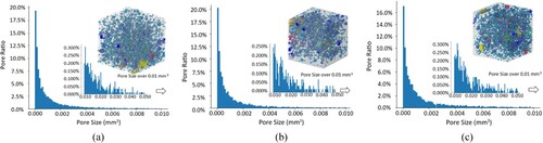
Figure 13. Pore size distribution of the sprayed coating with air injection pressure of (a) 0.5 Bar, (b) 1 Bar and (c) 1.5 Bar.
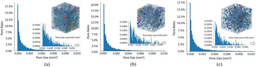
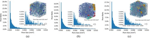
Figure 14. Pore size distribution of the sprayed coating with nozzle standoff distance of (a) 50 mm, (b) 75 mm and (c) 100 mm.
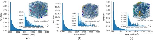
illustrates the influence of air injection pressure on pore size distribution. As the pressure rises from 0.5 Bar to 1 Bar, there is a noticeable decrease in the proportion of larger pores, accompanied by an increase in smaller pores. This phenomenon can be attributed to the breakdown of large pores into smaller ones. With further increase of pressure, these smaller pores were expelled from the matrix, leading to a reduction in the overall porosity. In addition, the orientation of the spray exhibits a noticeable influence on pore size distribution (). Coatings applied in horizontal or overhead directions tend to exhibit a higher proportion of larger pores compared to other specimens.
Figure 15. Pore size distribution of the sprayed coating with (a) vertical, (b) horizontal and (c) overhead spray.
3.3. Piezoresistive performance of coated specimens under cyclic loading
demonstrates the piezoresistive responses of the spray-coated samples subjected to two different loading scenarios: cyclic compression ((a)) and cyclic bending ( (b)).
Figure 16. Piezoresistive response of self-sensing coating under (a) cyclic compression and (b) cyclic bending.
The coating was applied to the surface parallel to the loading direction for the compressive scenario. Samples exhibit a decrease in electrical resistivity during the loading phase and an increase in electrical resistivity during the unloading phase. This change is attributed to the reduced spacing between the adjacent CF, which leads to an increase in fibre overlap and, consequently, a shorter conductive path within the coating composite. During the unloading phase, the fibres recover to their original position, thus extending the conductive path and increasing the resistivity. For the bending scenario, the coating was applied to the bottom surface of the beam, thereby subjected to tensile strain during loading, which behaves inversely compared to the compressive scenario.
The change in FCR (ΔFCR) under cyclic loading as illustrated in , highlights the sensitivity of the piezoresistive performance. Although the applied loads for compression and flexural scenarios are different, and sensitivity increases with the increase of applied load, both tests were conducted within the elastic range of the material. This ensures that they are still comparable when evaluating the piezoresistive performance of the coating. The piezoresistivity tests in both compressive and flexural scenarios obtained the maximum sensitivity before any damage occurred, allowing for an assessment of the sensing performance of the material close to its capacity. A more pronounced ΔFCR is observed in the sample subjected to bending compared to the sample under compression, indicating the applied coating is more sensitive to tensile stress.
In the compressive scenario ( (a)), a continuous increase of FCR over time is noted. This phenomenon can be attributed to the polarisation effects resulting from the movement of the ions within the specimens. When a direct current is applied, the movement of ions creates an internal electric field with a direction opposite to the applied current, and consequently leads to an increase in measure resistance. However, as the pretreatment process effectively eliminated most of the free water within the composite and consequently minimised the effect of polarisation; therefore, the observed increase in FCR is primarily attributed to the deformation of the conductive network within the composite, likely resulting from fibre debonding under applied load. These indicate that it is essential to understand the recoverability of the conductive network after external loading is removed, which could be defined as the repeatability of the signal.
Beyond sensitivity and repeatability, stability is another factor that is important in evaluating the sensing performance of the coating, which refers to the consistency of the piezoresistive response over time and under varying conditions.
3.4. Impact of robotic spray parameters on piezoresistive performance
The subsequent analysis focuses on the piezoresistive performance of the coating applied under varied spray parameters (). This includes the calculation of the average ΔFCR from 10 loading cycles, which quantified the sensitivity of the coating. The standard deviation of ΔFCR was calculated, indicating the stability of the piezoresistive response. The overall change in FCR (FCRt) throughout the testing process provides a measure of the repeatability of the coating when subjected to cyclic loading conditions. The repeatability is closely related to stability, as observed in , where higher stability correlates with a lower FCRt, indicating good repeatability. This proves the recovery ability of the conductive networks after the removal of the applied load.
Figure 17. piezoresistive performance of the coating subjected to (a) cyclic compression and (b) cyclic bending.
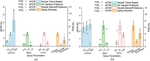
By comparing the data from (a) and (b), it appears that variations in spray parameters produce consistent trends in piezoresistive performance, both under cyclic compression and cyclic bending. Specifically, ΔFCR values are slightly higher when subjected to bending forces compared to compression, highlighting the coating exhibits higher sensitivity to bending. Coatings applied at a speed of 150 mm/s exhibit the highest average ΔFCR, suggesting that thinner coatings are more sensitive to the deformations of the substrates. There appears to be an inverse relationship between sensitivity and stability, where the increased sensitivity in the coating correlates with diminished stability. At a spray setting of 0.5 bar and a distance of 50 mm, the coating displays a lower ΔFCR. This outcome is consistent with the coating's interlayer bonding strength, which is also possibly due to a less compact coating structure and its inadequate coverage. The coating with higher porosity tends to have a reduced effective contact area with the substrate, which compromises the sensitivity of the coating. In addition, higher porosity can lead to poor bonding between the conductive fibres and the matrix, resulting in a higher chance of fibre debonding when subjected to external loading, consequently leading to poor repeatability of the coating sensing performance. Moreover, the presence of pores within the coating structures can disrupt the continuity of the conductive networks, reducing the coating's overall sensing performance in terms of accuracy and stability. When the pressure and standoff distance increase to 1 bar and 75 mm, respectively, the overall performance of the self-sensing coating improves, which is attributed to the improved bonding strength and denser structures. Stronger bonding enhances the transfer and distribution of mechanical stress throughout the coating and, consequently, improves its piezoresistive response. However, when the pressure and nozzle standoff distance further increased to 1.5 bar and 100 mm, a reduction in ΔFCR was observed, which could be attributed to the denser structure of the coating [Citation38]. Such a dense structure is inherently more resistant to deformation, affecting its piezoresistive response. Regarding the direction of spray application, coatings applied in a horizontal or overhead direction exhibit lower sensitivity compared to those applied vertically. Although the bonding strength affects the piezoresistive performance of the coating, the primary determinant appears to be the internal structure of the coating itself, which is consistent with the finding in coating porosity where the porosity is lower for vertical direction, higher for horizontal direction, and highest for overhead direction. Correspondingly, the bond strength is inversely related to porosity. Higher bond strength generally leads to piezoresistive performance; however, a denser microstructure in the coating limits the deformation of the conductive network, resulting in less significant sensing sensitivity. It is important to improve the bonding strength of the coating without affecting its microstructure. The use of bonding agents could be considered in future studies. Additionally, the orientation of spray printing affects the alignment and distribution of CFs within the coating, which impacts its conductive networks and, consequently, the piezoresistive behaviour. During the spray process, CFs may curl up, which can negatively affect the sensing performance. Future research could explore the use of more porous functional fillers and a combination of fibrous and particle materials to enhance the piezoresistive performance.
3.5. Assessment of self-sensing performance through load-to-failure tests.
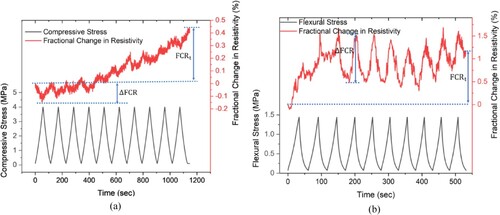
illustrates the correlation between FCR and the applied axial compressive stress and the bending load up to the point of failure, which aims to assess the capability of the self-sensing spray coating in monitoring the progression of the real-time crack development.
Figure 18. Fractional change in resistivity in coated specimens when subjected to (a) compressive and (b) flexural load to failure.
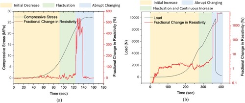
For the sample subjected to compression, the FCR initially decreases, corresponding to the compaction of the conductive network under pressure. This is followed by the fluctuation phase of FCR due to the formation of fresh cracks, which lead to the destruction and reconstruction of the conductive networks. Finally, an abrupt increase in FCR could be observed, which results from a disruption in conductive networks caused by the extension of cracks and the failure of the specimens [Citation15].
Conversely, the sample under bending initially exhibits a slight increase in FCR with the increasing bending load, which is likely attributed to the inherent electrical charges of CFs [Citation39]. The FCR begins to show significant fluctuations and increases once the initial crack forms at the tensile face of the beams. The expansion of crack width can lead to an increase in the conductive path resulting from the CF fracturing and being pulled out from the surrounding matrix, which is reflected in the continued growth of FCR [Citation40, Citation41]. Finally, a sudden reduction in the flexural loading with an abrupt change in the corresponding FCR can be observed, attributed to the fracture of the coating, thus indicating the compromise of the structure.
3.6. Practical application of developed material
The piezoresistive properties of the self-sensing cementitious coatings applied using 3D robotic spray technology could enable real-time monitoring of structural performance, which is crucial for the maintenance and safety of civil infrastructure. The self-sensing cementitious coating could achieve real-time response to various external loading conditions, allowing them to monitor structural deformations, identify potential failure points, and provide insights for preventive maintenance.
The self-sensing cementitious coating can be applied to critical structural components such as bridges, existing buildings and tunnels where traditional monitoring methods are either costly or challenging to implement. The robots can operate in environments that are difficult for human access, which also enhances safety and efficiency.
With further improvements in the mechanical properties of the coating, it could be applied to critical points of the structure or the location that have suffered previous damages, providing multi-functions such as sensing materials and repairing materials. Further research could explore integrating the sensing responses of the coatings into an automated system that could trigger alerts based on continuous monitoring data.
This study innovatively employed robotic 3D spray technology for sensing coating applications and offered critical insights into spray parameters optimisation for enhancing coating sensing performance. However, despite the fact that it comprehensively explored the correlation between spray parameters and coating characteristics, the optimal combination of these parameters remains undetermined. Future research will focus on optimising this combination and exploring a wider variety of functional fillers, which aims to enhance the sensing performance of the coating, paving the way for SHM applications.
4. Conclusions
This study was done to investigate the impact of spray parameters on the mechanical strength, adhesion properties and piezoresistive behaviour of the sprayed self-sensing cementitious composite coating. An ABB robotic arm was utilised to conduct spray by varying the spray parameters, including nozzle travel speed, air injection pressure, nozzle standoff distance and spray directions. Based on the test results, the conclusions can be summarised as follows:
Overall, the application of the coating has a negligible impact on the strength of the concrete substrate. Applying the coating at a nozzle travel speed of 75 mm/s results in enhanced compressive strength, indicating potential for structural reinforcement. In terms of flexural strength, although certain spray conditions can slightly improve the substrate's strength, specific orientations lead to coating weaknesses. The initiation of cracks within the coating under these orientations may accelerate the early failure of the concrete substrate.
Air injection pressure and nozzle standoff distance effectively contribute to the bonding strength of spray coatings to concrete substrates. The bonding strength of the coating improves with the increasing air pressure, with an optimal air pressure of 1.5 Bar. Additionally, increased nozzle standoff distance is found to enhance bonding, attributed to better coverage and a compressive effect on the overlaying coating layers.
CT scanning evaluation revealed that optimal air pressure and spray orientation significantly reduced the porosity of cementitious coatings, leading to stronger bonding with the substrate by minimising shrinkage and improving mechanical interlocking.
The piezoresistive performance of the sprayed coatings was influenced by spray parameters, showing distinct sensitivity, stability, and repeatability under cyclic loading. Coatings exhibit higher sensitivity to bending than compression, with thinner coatings applied at faster speeds being particularly responsive. Optimal spray conditions, such as a pressure of 1.5 bar and a distance of 100 mm, lead to denser coatings with lower sensitivity but potentially higher stability.
The coating exhibits a similar three-phase piezoresistive response when subjected to compression and bending, which can be characterised as an initial FCR changing phase, fluctuation phase and abrupt increase phase. This demonstrates its ability to detect structural deformations, crack formations, and failures in real-time, suggesting its potential in SHM applications.
Declaration of competing interest
The authors declare no conflict of interest.
Acknowledgment
This research is supported by the National Research Foundation, Prime Minister's Office, Singapore under its Medium-Sized Centre funding scheme, CES_SDC Pte Ltd, and Chip Eng Seng Corporation Ltd.
Disclosure statement
No potential conflict of interest was reported by the author(s).
Data availability
The raw/processed data of this study are available from the corresponding author upon reasonable request.
Additional information
Funding
References
- Zhang C, et al. Mix design concepts for 3D printable concrete: a review. Cem Concr Compos. 2021;122; doi:10.1016/j.cemconcomp.2021.104155.
- Weng Y, et al. Comparative economic, environmental and productivity assessment of a concrete bathroom unit fabricated through 3D printing and a precast approach. J Clean Prod. 2020;261:121245), doi:10.1016/j.jclepro.2020.121245.
- Zhou W, Zhang Y, Ma L, et al. Influence of printing parameters on 3D printing engineered cementitious composites (3DP-ECC). Cem Concr Compos. 2022;130; doi:10.1016/j.cemconcomp.2022.104562.
- Hou S, Duan Z, Xiao J, et al. A review of 3D printed concrete: performance requirements, testing measurements and mix design. Constr Build Mater. 2021;273; doi:10.1016/j.conbuildmat.2020.121745.
- Du S, et al. A BIM-enabled robot control system for automated integration between rebar reinforcement and 3D concrete printing. Virtual Phys Prototyp. 2024;19(1):e2332423), doi:10.1080/17452759.2024.2332423.
- Liu X, Cai H, Ma G, et al. Spray-based 3D concrete printing parameter design model: actionable insight for high printing quality. Cem Concr Compos. 2024;147; doi:10.1016/j.cemconcomp.2024.105446.
- Heidarnezhad F, Zhang Q. Shotcrete based 3D concrete printing: state of art, challenges, and opportunities. Constr Build Mater. 2022;323:126545), doi:10.1016/j.conbuildmat.2022.126545.
- Rao RK, Sasmal S. Smart nano-engineered cementitious composite sensors for vibration-based health monitoring of large structures. Sens Actuators A Phys. 2020;311:112088), doi:10.1016/j.sna.2020.112088.
- Abebe TN, Woo B-H, Kim HG, et al. Real-time monitoring of self-sensing cementitious composite incorporating hybrid silicon carbide and graphite for enhanced structural health monitoring. Cem Concr Compos. 2023: 105404.
- Zhao J, Bao T, Chen S, et al. Smart aggregate-piezoceramic patch combination for health monitoring of concrete structures. J Sens. 2016;2016.
- Wang RL, Gu H, Mo YL, et al. Proof-of-concept experimental study of damage detection of concrete piles using embedded piezoceramic transducers. Smart Mater Struct. 2013;22(4):0042001), doi:10.1088/0964-1726/22/4/042001.
- Ostachowicz W, Soman R, Malinowski P. Optimization of sensor placement for structural health monitoring: A review. Struct Health Monit. 2019;18(3):963–988. doi:10.1177/1475921719825601.
- Liu Y, Nayak S. Structural health monitoring: state of the art and perspectives. Jom. 2012;64(7):789–792. doi:10.1007/s11837-012-0370-9.
- Wang L, Aslani F. A review on material design, performance, and practical application of electrically conductive cementitious composites. Constr Build Mater. 2019;229:116892), doi:10.1016/j.conbuildmat.2019.116892.
- Han B, Ding S, Yu X. Intrinsic self-sensing concrete and structures: A review. Measurement ( Mahwah N J). 2015;59:110–128. doi:10.1016/j.measurement.2014.09.048.
- Abedi M, Fangueiro R, Correia AG. A review of intrinsic self-sensing cementitious composites and prospects for their application in transport infrastructures. Constr Build Mater. 2021;310:125139), doi:https://doi.org/10.1016/j.conbuildmat.2021.125139.
- Han J, Pan J, Cai J, et al. A review on carbon-based self-sensing cementitious composites. Constr Build Mater. 2020;265:120764), doi:10.1016/j.conbuildmat.2020.120764.
- Aguirre-Guerrero AM, Robayo-Salazar RA, de Gutiérrez RM. A novel geopolymer application: coatings to protect reinforced concrete against corrosion. Appl Clay Sci. 2017;135:437–446. doi:10.1016/j.clay.2016.10.029.
- McAlorum J, Perry M, Vlachakis C, et al. Robotic spray coating of self-sensing metakaolin geopolymer for concrete monitoring. Autom Constr. 2021;121:103415), doi:10.1016/j.autcon.2020.103415.
- Lu B, et al. Designing spray-based 3D printable cementitious materials with fly ash cenosphere and air entraining agent. Constr Build Mater. 2019;211:1073–1084. doi:https://doi.org/10.1016/j.conbuildmat.2019.03.186.
- Ercan Jenny S, et al. Robotic plaster spraying: crafting surfaces with adaptive thin-layer printing. 3D Print Addit Manuf. 2022;9(3):177–188. doi:10.1089/3dp.2020.0355.
- Lu B, Li H, Wong TN, et al. Development of a functional cementitious mixture with expanded graphite for automated spray construction. J Mater Civ Eng. 2023;35(8):04023226), doi:10.1061/JMCEE7.MTENG-14854.
- Lu B, Wang L, Wang X, et al. Development of robotic sprayable self-sensing cementitious material for smart structural health monitoring. Addit Manuf. 2024;85:104161), doi:https://doi.org/10.1016/j.addma.2024.104161.
- Han B, Zhang K, Yu X, et al. Fabrication of piezoresistive CNT/CNF cementitious composites with superplasticizer as dispersant. J Mater Civ Eng. 2012;24(6):658–665. doi:10.1061/(ASCE)MT.1943-5533.0000435.
- Lu B. et al., “Effect of spray-based printing parameters on cementitious material distribution,” in 2018 international solid freeform fabrication symposium, University of Texas at Austin, 2018.
- A. I. C. C. on C. and C. Aggregates, Standard test method for splitting tensile strength of cylindrical concrete Specimens1. ASTM international, 2017.
- Weng Y, Li M, Wong TN, et al. Synchronized concrete and bonding agent deposition system for interlayer bond strength enhancement in 3D concrete printing. Autom Constr. 2021;123:103546), doi:10.1016/j.autcon.2020.103546.
- Weng Y, Li M, Zhang D, et al. Investigation of interlayer adhesion of 3D printable cementitious material from the aspect of printing process. Cem Concr Res. 2021;143:106386), doi:10.1016/j.cemconres.2021.106386.
- Rocco C, Guinea GV, Planas J, et al. Size effect and boundary conditions in the Brazilian test: theoretical analysis. Mater Struct. 1999;32(6):437–444. doi:10.1007/BF02482715.
- Weng Y, et al. Feasibility study on sustainable magnesium potassium phosphate cement paste for 3D printing. Constr Build Mater. 2019;221:595–603. doi:10.1016/j.conbuildmat.2019.05.053.
- Geng Z, et al. Layer-interface properties in 3D printed concrete: dual hierarchical structure and micromechanical characterization. Cem Concr Res. 2020;138:106220), doi:10.1016/j.cemconres.2020.106220.
- Lu B, Li M, Wong TN, et al. Effect of printing parameters on material distribution in spray-based 3D concrete printing (S-3DCP). Autom Constr. 2021;124:103570), doi:https://doi.org/10.1016/j.autcon.2021.103570.
- Nolte N, Heidmann-Ruhz M, Krauss HW, et al. Development of shotcrete mixtures with controllable properties for the additive manufacturing of concrete structures. Spritzbeton-Tagung. 2018: 1–13.
- Beushausen H, Alexander MG. Bond strength development between concretes of different ages. Mag Concr Res. 2008;60(1):65–74. doi:10.1680/macr.2007.00108.
- Kloft H, et al. Influence of process parameters on the interlayer bond strength of concrete elements additive manufactured by shotcrete 3D printing (SC3DP). Cem Concr Res. 2020;134:106078), doi:10.1016/j.cemconres.2020.106078.
- Zareiyan B, Khoshnevis B. Effects of interlocking on interlayer adhesion and strength of structures in 3D printing of concrete. Autom Constr. 2017;83:212–221. doi:10.1016/j.autcon.2017.08.019.
- Talbot C, Pigeon M, Beaupre D, et al. Influence of surface preparation on long-term bonding of shotcrete. Materials Journal. 1995;91(6):560–566.
- Dong W, Li W, Vessalas K, et al. Piezoresistivity deterioration of smart graphene nanoplate/cement-based sensors subjected to sulphuric acid attack. Composites Communications. 2021;23:100563), doi:https://doi.org/10.1016/j.coco.2020.100563.
- Al-Dahawi A, Öztürk O, Emami F, et al. Effect of mixing methods on the electrical properties of cementitious composites incorporating different carbon-based materials. Constr Build Mater. 2016;104:160–168. doi:10.1016/j.conbuildmat.2015.12.072.
- Sarwary MH, et al. Self-sensing of flexural damage in large-scale steel-reinforced mortar beams. ACI Mater J. 2019;116(4):209–221.
- Chung DDL. Damage detection using self-sensing concepts. Proc Inst Mech Eng G J Aerosp Eng. 2007;221(4):509–520. doi:10.1243/09544100JAERO203.