Abstract
Background Modern navigation techniques allow precise positioning of the acetabular cup relative to the anterior pelvic plane. Variations in pelvic tilt will affect the resulting spatial orientation of the cup.
Methods We measured pelvic tilt in 30 volunteers with an inclinometer combined with an ultrasonographic position measurement system. A mathematical algorithm was developed to calculate the resulting cup position measured on standard radiographs, depending on pelvic tilt.
Results Average pelvic tilt at rest was −4° in the lying position and −8° in the standing position, and ranged from −27° to +3°. Pelvic reclination of 1° will lead to functional anteversion of the cup of approximately 0.7°.
Interpretation Pelvic tilt makes navigation systems referring to the anterior plane inaccurate.
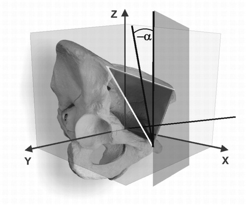
Acetabular prosthetic cups can be positioned precisely by the use of navigation systems. Most navigation systems refer cup alignment to anatomical landmarks of the pelvis, most commonly the anterior superior iliac spines and the pelvic symphysis that define the anterior pelvic plane. The orientation of the anterior pelvic plane can differ considerably in the standing or lying position with respect to the frontal plane. This difference is defined as pelvic inclination (angle alpha in ). Zero pelvic inclination occurs when the anterior pelvic plane is parallel to the frontal plane. It is only in this special case that inclination and anteversion of the cup appear identical using the navigation system and on postoperative standard radiographs.
Figure 1. Pelvic reclination (angle α si negative).
Every movement of the anterior pelvic plane caused by tilting of the pelvis must result in a difference between intraoperatively prescribed implanting angles and postoperatively measured cup alignment. Pelvic tilt is therefore a factor of uncertainty in navigation systems.
We present a method for dynamic measurement of pelvic tilt, and a mathematical algorithm to correct the implanting angles of the position of the cup to the resulting functional position, depending on pelvic tilt.
Measuring pelvic tilt
A method for measurement of pelvic tilt of the anterior plane was introduced by Anda et al. (Citation1990). These authors constructed an inclinometer that could be pressed firmly against the anterior pelvic spines and the symphysis. Pelvic inclination was measured with goniometers mounted onto the inclinometer. On average, pelvic inclination was −6° in men and –4.3° in women in the standing position, with no or minor difference relative to the lying position. On the other hand, two radiographic studies have revealed significant differences (DiGioia et al. Citation1998, Eddine et al. Citation2001). The results of Andas et al. appear to be questionable because they were not validated against distortion through overlying tissue. These authors suppose that the “anterior iliac spines and the symphysic tubercles are.. probably covered by approximately the same amount of soft tissue.” In addition, they conclude: “This may not be so in overweight persons, and measurement of the reference plane may consequently be slightly inaccurate in these cases” (Anda et al. Citation1990). Thus, the depth of the overlying tissue must be measured in order to assess pelvic inclination accurately.
Pelvic inclination and spatial orientation of the acetabulum
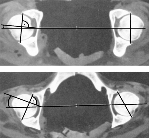
With pelvic tilt accurately measured, it still remains unclear to what extent a pelvic inclination of −10 degrees, for example, changes the values of acetabular alignment of an implanted cup. The principal influence of pelvic inclination on the radiographic measurements of acetabular inclination—and especially anteversion—is well understood (Visser and Konings Citation1981, Reikeras et al. Citation1982, Anda et al. Citation1986, Eddine et al. Citation2001). With rotation of the pelvis flexed forward, less anteversion of the acetabulum will be measured radiographically ().
Figure 2. Retroversion of pelvis (lower graph) results in increasing anteversion of the acetabulum.
Only one study has been published that quantified the relationship between pelvic inclination and anteversion measured on a CT scan. In their CT study of cadavers, Anda et al. (Citation1990) found that acetabular anatomical anteversion varied by approximately 0.5° with pelvic rotation of 1°. Unfortunately, the mathematical model presented in their paper was deduced only descriptively, but not analytically. To date, no mathematical model has been presented that allows the clinician to correct the implanting angles to conveniently measured radiographic angles, the acetabular inclination from anteroposterior radiographs and the acetabular anteversion from axiolateral radiographs, depending on the amount of pelvic inclination.
Material and methods
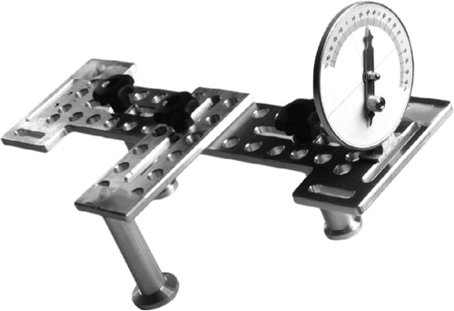
We constructed an inclinometer according to the one used by Anda et al. (Citation1990) (). It consists of three 10-cm-long blocks that are attached in an adjustable manner to the inclinometer. In order to measure the pelvic tilt, we used an additional ultrasound position tracking system (Zebris CMS 100, Isny, Germany) recording the coordinates of 3 markers adjusted to the plane of the inclinometer. The tracking system works with a sampling rate of 10 Hz and provides marker position with a precision of less than 1 mm for each Cartesian spatial component. A reference marker system was adjusted to the wall of the room in order to define two reference axes: a line vertical to the floor of the room served as a reference axis to calculate the pelvic inclination in the standing position, whereas a horizontal axis parallel to the longitudinal axis served this purpose for calculation of pelvic inclination in the supine position. Zebris coordinate data of the markers were processed in MatLab (The Mathworks Inc., Natick, MA) to calculate pelvic orientation.
Figure 3. Calculation of the correction angle. H is the depth of tissue over the ASIS, h' is the depth of tissue over the symphysic tubercles, and d is the distance between the symphysis and a line between the two ASIS.
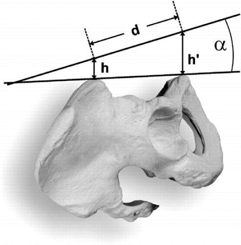
Figure 4. Construction of the inclinometer. There are 3 ultrasound markers and an angle measurer fixed to the instrument.
Firstly, we tested the accuracy of the measuring setup by putting the inclinometer on a construction block with defined wedges serving as a benchmark.
For the clinical investigation, 30 young adults (17 men) aged between 20 and 43 years volunteered to participate. They had no history of orthopedic or neurological disorders and no apparent leg differences. Each subject lay supine on a hard bench. The anterior iliac spines and the symphysic tubercles were palpated and marked with adhesive stars, and the distance, d, between the line connecting the anterior iliac spines and the symphysis was measured. The depth of the intervening tissue, i.e. the skin and subcutaneous tissue, was measured with a 7.5-MHz ultrasound device over the anterior superior spine and over the tubercles (). Because we had measured the distance, d, between both landmarks, it was now possible to calculate the correction angle δ by the relationship tan(δ) ≈ sin(δ) = (h′ − h) / d. (small angles assumed).
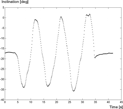
As illustrated in , pelvic inclination was measured firstly in a relaxed position and then from maximum inclination to reclination. This course has to be repeated three times, each in the lying and standing position. The measurement finished again in the relaxed position. Inclination at the relaxed positions was determined for at least 30 data values on average. The values of relaxed inclination before and after pelvic movement were compared using a two-sided paired t-test (p < 0.05). Range of motion was defined as the difference between the mean values of maximum inclination and reclination, respectively. In order to evaluate the reproducibility of the measurements, the first 10 subjects were measured twice on the same day. Relaxed inclination as well as maximum inclination and reclination were compared for each pair of measurements.
Figure 5. Typical time course of pelvic inclination and reclination.
Results
We first tested the accuracy of our measurement set-up. We were able to measure the predefined angles of the wedge blocks with a precision of less than 1 degree.
Clinical course
Pelvic reclination was −8° on average in the lying position, and −12° in the standing position (). The measurements revealed considerable variation between individuals, ranging from −17° to +3° in the lying position and from −27° reclination to +3° inclination in the standing posture.
Table 1. Pelvic inclination in supine and standing posture measured in 30 probands
The values for pelvic inclination at the beginning and end of each course () were not significantly different. There was a wide variation in range of motion (ROM) between the volunteers, ranging from 9° in the supine position to 46° in the standing position (). Pelvic inclination at rest (–8° in the supine position and −12° in the standing position) seems to be a posture that is located midway between maximum inclination and reclination.
Table 2. Range of motion (ROM) of pelvic tilt in the standing and lying posture measured in 30 probands
On average, the measurements for the reproducibility of the values for relaxed inclination and maximum inclination and reclination showed differences of less than 1.5° between two repeated measurements (SD < 3.5). The results of the anthroprometric and sonographic measurements for calculation of the correction angle are given in . The symphysis was covered with more tissue (mean 16.1 mm) than the anterior iliac superior spine (mean 7.1 mm). Thus, the bony anterior pelvic plane lies less reclined than would appear from our measurements performed on the surface. The necessary correction angle is 4.4° on average, with variation from 1.3° to 5.5°.
Table 3. Values of anthroprometric and sonographic measurements, and correction angle
Mathematical correction algorithm
Acetabular orientation of the cup is described by its inclination and anteversion. According to Murray (Citation1993), there are at least 3 definitions of acetabular inclination and anteversion: radiographic or planar, derived from anteroposterior and axiolateral radiographs, anatomical, which can be derived from CT slides, and operative orientation, which is delivered by most of the implanting rods. Here, we present a mathematical correction algorithm to determine how pelvic inclination affects the functional position of the cup as measured on standard radiographs. We have thus used the radiographic definition of Murray (Citation1993).
A pelvic inclination by an angle ϕ caused by a rotation of the pelvic plane through a transversal axis changes the radiographic anteversion RA0 to a value RAϕ, depending of the value of the radiographic inclination RI0.
Equation (1)
Simultaneously, the radiographic inclination RI0 is changed to RIϕ:
Equation (2)See Appendix.
Discussion
Our method of measuring pelvic tilt with an inclinometer and a sonographic tracking system provides reliable and reproducible data. Anda et al. (Citation1990) used an inclinometer with commercial instruments for angle measurement, and they were able to demonstrate good intraobserver reliability.
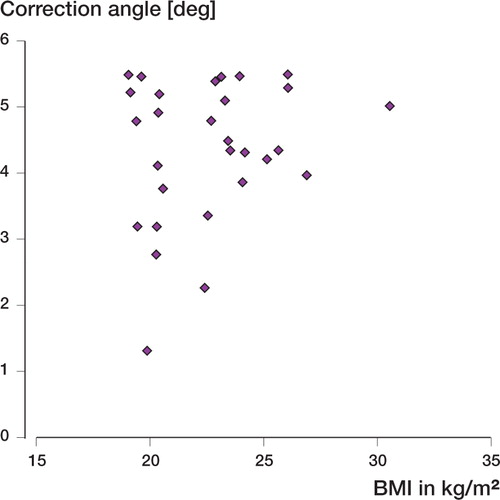
In the present study, it was possible to measure the deviation from inclination of the body surface to the bony anterior pelvic plane. The results () show that the angles measured on the surface must be corrected to a more inclined position by about 4.4° on average. There appears to be no direct relationship between obesity and correction angle (). Correction angles over 5° can be found in both lean and stout subjects. The amount of skin seems to increase somewhat proportionally over the symphysis and the anterior iliac spines with increasing body mass index. If we subtract the average correction angle of 4.4° this results in an average pelvic inclination of −8° in the standing position and −4° in the lying position, approaching a neutral position for the anterior pelvic plane on average.
Figure 6. Relationship between correction angle and body mass index.
Anda et al. (Citation1990) reported values between −6° in men and −4° in women to be the average, with no significant differences between the lying and standing positions. As with our values, they found that values for pelvic inclination at rest can vary by about 30° between two subjects. Range of motion was comparable in both studies, ranging between 20° and 25° on average.
Approximately 1° of pelvic inclination requires a correction of radiographic acetabular anteversion (RA) of 0.7°. The average reclination of the anterior pelvic plane was approximately −4° in the lying position, resulting in a functional retroversion of the cup of approximately 2.8° (), which is probably of minor importance. If the patient changes to the standing position, the anterior pelvic plane will shift to −8° on average—resulting in 5.6° more anteversion than implanted. Thus, the surgeon should consider prescribing less anatomical anteversion when using a navigation system. Because pelvic tilt can be performed equally toward inclination and reclination (), this requires no correction. There were individuals with a pelvic reclination of −17° in the lying position and −27° in the standing position (). In such subjects, cup implantation with 15° of anatomical anteversion would result in a functional position of the cup of −27° in the lying position and −34° in the standing position (), which indicates a clear risk of hip dislocation (Lewinnek et al. Citation1978).
Figure 7. Corrected angle of radiographic anteversion RA vs. pelvic inclination. The diagram illustrates the effect of pelvic tilt on radiographic anteversion for 3 values of radiographic anteversion (15, 25, and 35 degrees). Each simulation was done for 5 different values of radiographic acetabular inclination (RI = 30–50 degrees).
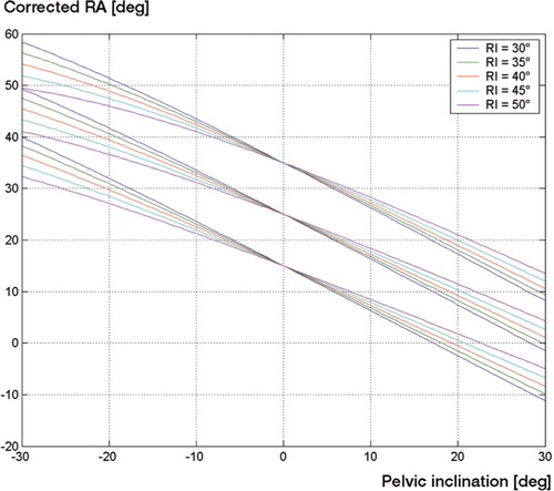
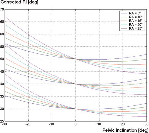
Figure 8. Corrected angle of radiographic inclination (RI) vs.pelvic inclination.The diagram illustrates the effect of pelvic tilt on radiographic inclination for 3 values of radiographic inclination (30, 40, and 50 degrees).Each simulation was done for 5 different values of radiographic acetabular anteversion (RA = 5–25 degrees).
The anterior pelvic plane can deviate substantially from the frontal plane in some individuals; thus, radiographic measurements of acetabular alignment are not comparable to surgical navigation alignment. The surgeon using a navigation system should consider prescribing less anteversion for the cup, because in most individuals the anterior pelvic plane tends to recline in the lying and standing position—resulting in a more anteverted functional position of the cup. Cup navigation that refers to the anterior pelvic plane must be regarded as imprecise because of pelvic tilt, and efforts should be made to develop navigation systems that place the acetabulum relative to the position of the femoral head. If there is uncertainty, pelvic tilt can be measured reliably with an inclinometer and the effect on the functional cup position can be calculated with the help of our algorithm.
Appendix
According to the definitions of Murray (Citation1993), the acetabular radiographic anteversion (RA) and inclination (RI) can be represented as the polar and azimuth angle of the normal vector, n, of the acetabular plane vector in a coordinate system with origin at the center of rotation of the hip joint.
The polar axis (z-axis) is normal to the coronal plane and is directed from dorsal to ventral. The xaxis is the direction of the transverse axis. A pelvic inclination is thus characterized by a rotation about the x-axis that depicts the line between the left and right centers of rotation of the hip. Mathematically, the acetabular plane vector n is transformed by a rotation matrix A to n′ n → n′ = An
In this coordinate system, the radiographic inclination angle (RI) represents the projection of the acetabular normal plane vector onto the coronal plane, i.e. tan(RI) = x/y and tan(RI’) = x’/y’, whereas the radiographic anteversion angle RA is the angle between the coronal plane and the acetabular normal plane vector, i.e. sin(RA) = z.
The authors wish to thank Thomas Mueller for his assistance with graphics.
No competing interests declared.
References
- Anda S, Svenningsen S, Dale L G, Benum P. The acetabular sector angle of the adult hip determined by computed tomography. Acta Radiol Diagn (Stockh) 1986; 27(4)443–7
- Anda S, Svenningsen S, Grontvedt T, Benum P. Pelvic inclination and spatial orientation of the acetabulum. A radiographic, computed tomographic and clinical investigation. Acta Radiol 1990; 31(4)389–94
- DiGioia A M, Jaramaz B, Blackwell M, Simon D A, organ F, Moody J E, Nikou C, Colgan B D, Aston C A, Labarca R S, Kischell E, Kanade T. The Otto Aufranc Award. Image guided navigation system to measure intraoperatively acetabular implant alignment. Clin Orthop 1998, 355: 8–22
- Eddine T A, Migaud H, Chantelot C, Cotten A, Fontaine C, Duquennoy A. Variations of pelvic anteversion in the lying and standing positions: analysis of 24 control subjects and implications for CT measurement of position of a prosthetic cup. Surg Radiol Anat 2001; 23(2)105–10
- Lewinnek G E, Lewis J L, Tarr R, Compere C L, Zimmerman J R. Dislocations after total hip-replacement arthroplasties. J Bone Joint Surg (Am) 1978; 60(2)217–20
- Murray D W. The definition and measurement of acetabular orientation. J Bone Joint Surg (Br) 1993; 75(2)228–32
- Reikeras O, Bjerkreim I, Kolbenstvedt A. Anteversion of the acetabulum in patients with idiopathic increased anteversion of the femoral neck. Acta Orthop Scand 1982; 53(6)847–52
- Visser J D, Konings J G. A new method for measuring angles after total hip arthroplasty. A study of the acetabular cup and femoral component. J Bone Joint Surg (Br) 1981; 63(4)556–9