
 ?Mathematical formulae have been encoded as MathML and are displayed in this HTML version using MathJax in order to improve their display. Uncheck the box to turn MathJax off. This feature requires Javascript. Click on a formula to zoom.
Abstract
This paper presents a 4 × 4 slot array antenna with ultra-wideband low-scattering characteristic, which integrates a metasurface based on the multielement phase cancellation (MEPC) method. Limited by the characteristics of the slot antenna array, the contradiction between the ideal radiation performance and the requirement of low radar cross section (RCS) has not been well resolved. Therefore, in this paper, a MEPC-based metasurface is designed as the cover-layer of the proposed antenna, which can disperse the reflected energy to more directions without degrading the radiation performance. The proposed antenna operates in a bandwidth of 3.89–4.00 GHz with a maximum gain of 14.3 dBi. Additionally, the 7 dB RCS reduction bandwidth for TE/TM polarization at normal incidence is 5.5–40 GHz (fh / fl = 7.27:1), achieving ultra-wideband out-of-band RCS reduction. Furthermore, low-scattering performance can remain stable at large-angle oblique incidence. To verify the feasibility of the proposed design, a prototype is fabricated and measured for demonstration. The simulated and measured results are in good agreement.
1. Introduction
The reason is that its structure is essentially obtained by slitting a larger metal surface, and the backward RCS is large, which is approximately equal to the same size metal plat so that the slot antenna system is the main contributing scattering source of the electronic platform. Consequently, the design of ultra-wideband low-scattering slot array antenna is becoming a critical challenge. With the escalation of present electronic detection, radar cross section (RCS) reduction technology gains more and more attention. Slot array antenna has the advantages of low manufacturing cost, high mechanical strength, low loss, etc. [Citation1,Citation2], but it is easier to be detected in practical applications. The reason is that its structure is essentially obtained by slitting a larger metal surface, and the backward RCS is large, which is approximately equal to the same size metal plat so that the slot antenna system is the main contributing scattering source of the electronic platform. Consequently, the design of ultra-wideband low-scattering slot array antenna is becoming a critical challenge.
Four methods are commonly used for antenna RCS reduction: shape stealth technology [Citation3,Citation4], radar absorbing material (RAM) technology [Citation5–8], opposite phase cancellation (OPC) technology [Citation9,Citation10], and polarization conversion technology [Citation11]. Due to the special nature of the slot array antenna operation, it is impossible to use methods of shaping and coating RAM used for stealth design in the antenna installation area. In recently year, polarization conversion metasurface [Citation12] and polarization rotation reflective surface (PRRS) [Citation13] are used as the cover-layer of slot array antenna to realize in-band and out-of-band RCS reduction, respectively, with good simultaneous preservation of radiation properties. However, the method of polarization conversion only transfers the energy from the co-polarized direction to its cross-polarized direction, which is still greatly limited in practical applications and cannot achieve ideal stealth.
Metasurfaces, ultra-thin structures with subwavelength dimensions, have lots of advantages such as low cost, low profile, and easy processing. Its utilization in the design of low-scattering antennas has received extensive attention. Ref. [Citation14] proposes a phase gradient metasurface (PGM) as the superstrate of the slot array to obtain a wideband RCS reduction. Based on the same principle, Ref. [Citation15] proposes a 90-degree phase difference metasurface slot array antenna and the measured RCS reduction exceeds 6 dB in the frequency band from 4.53 to 6.70 GHz. In addition, Ref. [Citation16] utilizes a modified substrate integrated waveguide (SIW) back-cavity slot antenna loaded with a novel coded metasurface to extend the radiative range while reducing the antenna inherent RCS ranging from 6.2 to 16.3 GHz. However, if the traditional OPC technology or PGM is used to reduce the antenna RCS, we will find that it is difficult to get appropriate settings of units that have a 180° phase difference in ultra-wide band. This is one of the important reasons why such method restricts the expansion of the operating bandwidth. In addition, in the daily working state of the antenna, we cannot predict the direction and polarization of incident waves. These unpredictable factors are extremely important as the challenges to the performance of antenna stealth. Thus, we will introduce the multielement phase cancellation (MEPC) method to overcome the issues of the above designs of low-scattering slot antenna to realize the monostatic and bistatic RCS reduction bandwidth expansion at the dual-polarized incoming waves, enhancing the antenna stealth performance.
In this paper, a slot array antenna with ultra-wideband low-scattering characteristic is proposed. Covered by a MEPC-based metasurface, this antenna can achieve ultra-wideband RCS reduction without degrading the radiation performance. The arrangement of this paper is as follows: The principle of MEPC method is described in Section 2. In Section 3, the design process of metasurface and low-RCS slot antenna is presented. And in this section, we compare the simulated and measured results of the reference antenna with the proposed antenna in terms of both radiation and scattering performance. Section IV is the conclusion. It should be noted that the metasurface lattices are slotted for ensuring the antenna normal radiation, which leads to a large asymmetry for the structure. Since to eliminate the effect of incident wave polarization on the asymmetric structure, we use the reflection results of the lattices instead of the units throughout the whole design and optimization process.
2. Description of multielement phase cancelation method
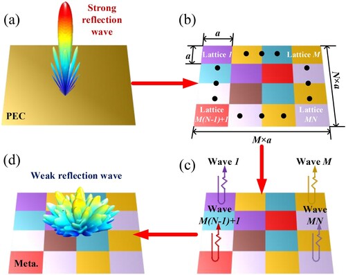
The mechanism of MEPC-based metasurface backward RCS reduction is exhaustively elucidated in Figure : As shown Figure (a), when the plane wave is incident perpendicular to the PEC plate, the electromagnetic wave will be specular reflected and the backward scattering energy is very strong. At this point we replace the PEC plate with an equal-sized metasurface consisting of M × N lattices (Figure (b)). Like Figure (c,d) shows that each lattice will generate its own local reflection wave, and these local reflection waves will superimpose in space. Finally, metasurface realizes the intensity weakening of the reflection wave in backward direction.
Figure 1. Schematic of MEPC-based metasurface backward RCS reduction mechanism.
Unlike the OPC technique, which produces a narrow RCS reduction bandwidth by exploiting the mutual cancellation of reflected wave due to a fixed 180° phase difference between the AMC and PEC lattices, the physical mechanism of the MEPC method is to superimpose multiple reflected waves generated by different lattices to achieve ultra-broadband phase cancellation. The RCS reduction (σR) at normal incidence of the metasurface compared to an equal-size PEC plate can be expressed as [Citation17],
(1)
(1) where Emeta, EPEC are the scattering field of the metasurface and equal-sized PEC plate, respectively. The reflection wave amplitude and phase of each lattice on the metasurface is Am,n, φm,n, and the whole scattering field is approximately the vector sum of the local reflection fields of M × N lattices. Similarly, since total reflection occurs on the PEC plate, the reflection amplitude is constant at 1, and its reflection field can be approximately equal to M × N. As can be seen from equation (1), RCS reduction has an infinite number of solutions by adjusting the parameters of each lattice. Namely, these backscattered waves can be adjusted independently to optimize the best broadband destructive interference. In addition, it cannot be ignored the synthetic scattering field is independent of the size, thickness and arrangement of the lattice as can be seen from equation (1).
Therefore, based on the MEPC method, the scattering fields with adjustable amplitude and phase can be synthesized by using variety lattices and the vector superposition is followed by an intelligent optimization algorithm selecting the appropriate elements to achieve RCS reduction within the maximum bandwidth.
3. Design of the low-scattering lot array antenna
3.1. Design of the proposed MEPC-Based metasurface
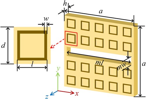
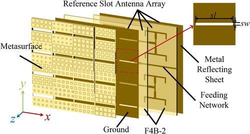
The metasurface has 4 × 4 lattices. Each lattice contains three layers, consisting of metal square ring on the top layer, a F4B-2 substrate (εr = 2.65, tanδ = 0.001) in the middle layer and the PEC ground at the bottom. As illustrated in Figure , a narrow groove is dug out in the center of the lattice, and then we arrange 2 × 5 unit-cells on each side. If such a groove is not subtracted instead of laying down the same 1 × 5 unit-cells, it will lead to a sharp performance decrease in radiation performance.
Figure 2. Geometry of the lattice. (d = 8.8 mm, ml = 40.5 mm, mw = 5.5 mm, a = 44 mm, w = 0.4 mm).
For realizing the multielement phase cancellation of the ultra-wideband scattering field of the antenna, it is necessary to find 16 kinds of unit-cells with their phase shift differences large enough to cover 360° in a wide band. Therefore, selecting the proper unit-cells is the first and most crucial step.
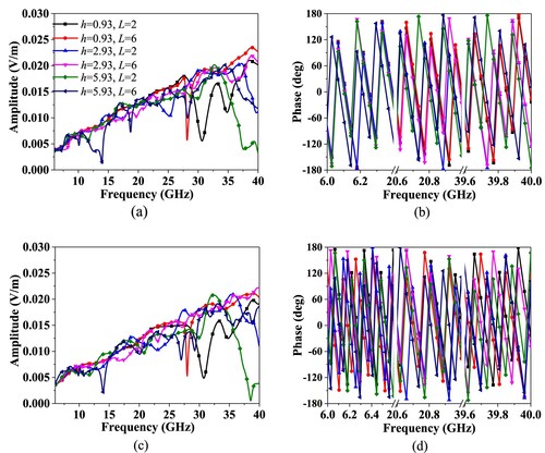
If the substrate thickness is fixed and cannot be adjusted, the path difference between the reflected waves on the upper and lower surfaces of the substrate is the same, and even if the size of the metal ring is changed, the problem of in-phase reflection is likely to occur. Thus, under this limitation, it is difficult to find a suitable set of unit-cell parameters, so that the phase difference of the reflection coefficient between the unit-cells completely covers the expected operating frequency, resulting in a bandwidth blind spot. To eliminate the bandwidth blind spot of RCS reduction, we will set different substrate thickness h, together with the length of the metal ring L, as parameters for optimization [Citation18].
The lattice structure is asymmetric, so the frequency domain solver of CST Microwave Studio cannot be used to evaluate the RCS like the previous study in [Citation19]. Therefore, we employ the transient solver to simulate the backscattered fields of the lattices with variable specifications. A part of the backscattered fields of the lattice varies with the length of the ring L and the thickness of substrate h at dual polarizations. As displayed in Figure , it is obvious to see that their phase shift differences large enough to cover 360° in a wide band.
Figure 3. Backscattered fields of the lattices under normal incidence at both polarizations. (a) Amplitude and (b) phase at x-polarization, (c) amplitude and (d) phase at y-polarization.
Particle swarm optimization (PSO) algorithm [Citation20], which is efficient and accurate, is often used for model optimization in microwave device design. We only need to put ample simulation results into the program, operate according to equation (1), and get the parameter array we need after several iterations. However, due to the asymmetry of the lattice structure, the result is inconsistent at x and y polarization, and it is necessary to alter the fitness function in the PSO algorithm. Considering the optimization results at dual polarizations, the fitness function is set as,
(2)
(2) and
(3)
(3) where σi R is the RCS reduction result at the sampling frequency i, and sx(i) and sy(i) respectively record the sampling frequency whose result is less than −10 dB at dual polarizations. The smaller fitness result demonstrates that the 10 dB RCS reduction result has a wider frequency band. After 1000 iterations, the best result is obtained, and the parameter settings are shown in Table . In Figure , without antenna structure, the optimal distribution of 16 lattices for the metasurface is depicted. The simulated RCS reduction shows that the RCS reduction bandwidth which is greater than 8 dB can range from 6.2 to 40 GHz (fh / fl = 6.45:1) for normal incidence at dual polarizations.
Figure 4. The simulated RCS reduction under normal incidence at dual polarizations.
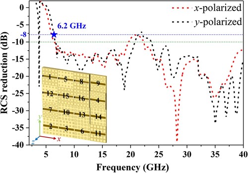
Table 1. The optimized results of 16 lattices (Unit: mm).
3.2. Radiation performance of proposed slot antenna
A conventional 4 × 4 slot array antenna (the reference antenna) and the proposed antenna are shown in Figure . As to the reference antenna. Its up-layer is a 16-slot metal ground printed on a 1 mm F4B-2 dielectric substrate, and the feed network system is on the below. In order to restrain the undesired back lobe and obtain boresight radiation, a metal-backed substrate with a thickness of 4 mm is placed below the feeding network. The slot length sl and width sw are 37.5 and 2.5 mm, respectively. This antenna operates in the frequency band of 3.89–4.00 GHz. The proposed antenna is identical to the reference antenna, except for the metasurface part. After covering the metasurface, the effective dielectric constant changes due to the introduction of undesirable wave superposition. The length and width of the lattice groove are optimized to be 3 mm longer than the reference antenna slot in order to make the antenna radiation performance more stable and reduce the effect on RCS reduction.
Figure 5. Geometry of proposed antenna with metasurface. (The reference antenna doesn’t contain the metasurface)
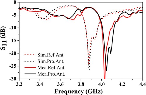
To validate the performance of proposed array antenna, the reference and proposed array antenna are fabricated which depicted in Figure . Comparing with the reference and proposed antenna simulated and measured return loss given in Figure , it is obvious to find that, despite the results between reference and proposed antennas are nearly in common, the measured results are shifted to the higher frequency for both antennas. Specifically, the operating frequency is moved up from 4.01 to 4.12 GHz, while the impedance bandwidth remains 110 MHz. The main reason of this phenomenon is the delamination treatment, the poor adhesion between the two layers, other manufacturing and installation errors, and measurement errors.
Figure 6. (a) The fabricated reference and (b) proposed slot antenna.
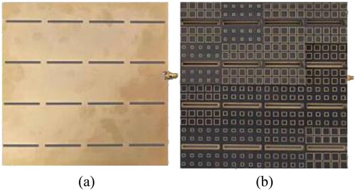
Figure 7. Simulated and measured return loss of the reference and proposed array antenna.
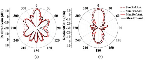
Since the resonant frequency is shifted toward high frequency, Figure compares the radiation performance at different resonant frequency point, which is the simulated radiation pattern results for the reference antenna and the proposed antenna at φ = 0° and φ = 90° at 3.90 GHz and measured at 4.10 GHz. The simulated radiation patterns almost coincide with the measured results, and the gain of the proposed antenna is 14.7 dBi, which is higher than the reference antenna. Consequently, the proposed slot array antenna keeps good radiation characteristic.
Figure 8. Simulated radiation patterns of both antennas at 3.90 GHz and measured radiation patterns of both antennas at 4.10 GHz. (a) φ = 0° (b) φ = 90°.
3.3. Scattering performance of proposed slot antenna
As shown in Figure , compared with metasurface structure, the magnitude of the antenna RCS reduction has changed slightly, but the overall reduction trend and bandwidth are almost constant. It is demonstrated that the metasurface structure can perfectly overcome the large scattering problem of slot antennas as the cover-layer of the antenna. The simulated results of this antenna cab achieve a stable reduction of 7 dB at dual polarizations in the wide band of 5.5–40 GHz. It is worth noting that the measurement results are better than the simulation results, and the RCS reduction of more than 12 dB in the same frequency band is achieved. Moreover, the scattering patterns at 18 GHz on UV coordinates is shown in Figure . It can be clearly seen that, compared with the scattering pattern of the PEC surface, because of the disordered lattice arrangement, the antenna disperses the electromagnetic waves in other directions, thereby weakening the energy in the direction of the incoming wave, which is reduced nearly 8 dB RCS in the main scattering direction.
Figure 9. The simulated RCS and measured RCS reduction of the reference antenna and the proposed antenna under normal incidence.
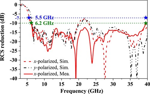
Figure 10. The simulated scattering patterns at 18 GHz on UV coordinates on (a) PEC surface and proposed antenna at (b) x-polarization (c) y-polarization.
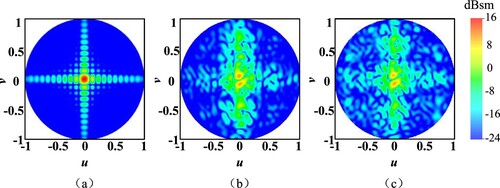
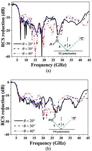
Figure shows the simulated RCS reduction results of the proposed slot array antenna under oblique incidences at TE and TM polarizations. For wide-angle incidences, the proposed antenna also can achieve ultra-wideband band RCS reduction at dual polarizations.
Figure 11. The simulated RCS reduction under oblique incidences for both polarizations. (a) TE-polarization, (b) TM-polarization.
A comparison of the RCS reduction bandwidth between the previous researches on low-scattering slot array antenna and this work is listed in Table . Obviously, our work has a great advantage in RCS reduction bandwidth extension, while still maintains the radiation performance of the slot array antenna. Thus, the proposed method of covering the metasurface produces a diffuse scattering pattern that leads to a good performance of the slot array antenna in terms of scattering in ultra-wideband, proving that this method is feasible and practical.
Table 2. Comparison between the proposed slot antenna and previous low-RCS designs.
4. Conclusion
A novel approach to achieve ultra-wideband RCS reduction of a slot array antenna under normal and oblique incidence is developed by covering a metasurface designed according to the MEPC method. Destructive interference is affected between multiple local waves which are generated from each lattice we selected by PSO algorithm, thus reducing the amplitude of the backscattered waves at multiple sampling frequencies. The proposed antenna realizes greater than 7 dB from 5.5 to 40 GHz (fh:fl = 7.27:1) at normal incidence for dual-polarization, while the radiation performance stays well. Measured and simulated results are in good agreement, fully demonstrating the feasibility of this approach to achieve the low-scattering function of the slot array antenna.
Disclosure statement
No potential conflict of interest was reported by the author(s).
Additional information
Funding
References
- Kim DY, Elliot RS. A design procedure for slot arrays fed by single-ridge waveguide. IEEE Trans Antennas Propag. 1988;AP-36(11):1531–1536. doi:10.1109/8.9701
- Green J, Shnitkin H, Bertalan PJ. Asymmetric ridge waveguide radiating element for a scanned planar array. IEEE Trans Antennas Propag. 1990;38(8):1161–1165. doi:10.1109/8.56951
- Jiang W, Liu Y, Gong SX, et al. Application of bionics in antenna radar cross section reduction. IEEE Antennas Wirel Propag Lett. 2009;8:1275–1278. doi:10.1109/LAWP.2009.2037168
- Dikmen CM, Çimen S. Planar octagonal-shaped UWB antenna with reduced radar cross section. IEEE Trans Antennas Propag. 2014;62(6):2946–2953. doi:10.1109/TAP.2014.2313855
- Liu T, Cao XY, Gao J, et al. RCS reduction of waveguide slot antenna with metamaterial absorber. IEEE Trans Antennas Propag. 2013;61(3):1479–1484. doi:10.1109/TAP.2012.2231922
- Chen Q, Guo M, Sang D, et al. RCS reduction of patch array antenna using anisotropic resistive metasurface. IEEE Antennas Wirel Propag Lett. 2019;18(6):1223–1227. doi:10.1109/LAWP.2019.2913104
- Shi Y, Chu PP, Kui Meng Z. An ultrawideband stacked metasurface with collaborative polarization conversion and absorption characteristic for application of radar cross section reduction. Waves Random Complex Media. 2022: 1–22. doi:10.1080/17455030.2022.2143927
- Su C, Ishimaru A, Kuga Y. Time-domain analysis of multiple scattering effects on the radar cross section (RCS) of objects in a random medium. Waves Random Complex Media. 2021;31(6):1905–1920. doi:10.1080/17455030.2019.1708513
- Kuznetsova S, Groby JP, Garcia-Raffi LM, et al. Stealth and equiluminous materials for scattering cancellation and wave diffusion. Waves Random Complex Media. 2021; doi:10.1080/17455030.2021.1948630
- Zheng YJ, Gao J, Xu LM, et al. Ultrawideband and polarization-independent radar-cross-sectional reduction with composite artificial magnetic conductor surface. IEEE Antennas Wirel Propag Lett. 2017;16:1651–1654. doi:10.1109/LAWP.2017.2660878
- Liu Y, Hao YW, Li K, et al. Radar cross section reduction of a microstrip antenna based on polarization conversion metamaterial. IEEE Antennas Wirel Propag Lett. 2016;15:80–83. doi:10.1109/LAWP.2015.2430363
- Liu Y, Li K, Jia YT, et al. Wideband RCS reduction of a slot array antenna using polarization conversion metasurfaces. IEEE Trans Antennas Propag. 2016;64(1):326–331. doi:10.1109/TAP.2015.2497352
- Jia YT, Liu Y, Zhang WB, et al. In-band radar cross section reduction of slot array antenna. IEEE Access. 2018;6:23561–23567. doi:10.1109/ACCESS.2017.2788043
- Zhang WB, Liu Y, Gong SX, et al. Wideband RCS reduction of a slot array antenna using phase gradient metasurface. IEEE Antennas Wirel Propag Lett. 2018;17(12):2193–2197. doi:10.1109/LAWP.2018.2870863
- Zhao Y, Cao XY, Gao J, et al. Broadband low-RCS circularly polarized array using metasurface-based element. IEEE Antennas Wirel Propag Lett. 2017;16:1836–1839. doi:10.1109/LAWP.2017.2682848
- Cheng YF, Liao C, Gao GF, et al. Performance enhancement of a planar slot phased array by using dual-mode SIW cavity and coding metasurface. IEEE Trans Antennas Propag. 2021;69(9):6022–6027. doi:10.1109/TAP.2021.3061583
- Su JX, He H, Lu Y, et al. Ultrawideband radar cross-section reduction by a metasurface based on defect lattices and multiwave destructive interference. Phys Rev Appl. 2019;11(4), doi:10.1103/PhysRevApplied.11.044088
- Su JX, Yu H, Yin HC, et al. Breaking the high-frequency limit and bandwidth expansion for radar cross-section reduction: a low-observable technology. IEEE Antennas Propag Mag. 2021;63(6):75–86. doi:10.1109/MAP.2020.3043464
- Modi AY, Balanis CA, Birtcher CR, et al. Novel design of ultrabroadband radar cross section reduction surfaces using artificial magnetic conductors. IEEE Trans Antennas Propag. 2017;65(10):5406–5417. doi:10.1109/TAP.2017.2734069
- Boeringer DW, Werner DH. Particle swarm optimization versus genetic algorithms for phased array synthesis. IEEE Trans Antennas Propag. 2004;52(3):771–779. doi:10.1109/TAP.2004.825102
- Genovesi S, Costa F, Monorchio A. Wideband radar cross section reduction of slot antennas arrays. IEEE Trans Antennas Propag. 2014;62(1):163–173. doi:10.1109/TAP.2013.2287888
- Li WQ, Cao XY, Gao JG, et al. A low RCS waveguide slot antenna array with metamaterial absorber. IEEE Trans Antennas Propag. 2015; doi:10.1109/TAP.2015.2431316
- Li K, Liu Y, Jia YT, et al. A circularly polarized high-gain antenna with low RCS over a wideband using chessboard polarization conversion metasurfaces. IEEE Trans Antennas Propag. 2017;65(8):4288–4292. doi:10.1109/TAP.2017.2710231
- Liu Y, Jia Y, Zhang WB, et al. Wideband RCS reduction of a slot array antenna using a hybrid metasurface. IEEE Trans Antennas Propag. 2020;68(5):3644–3652. doi:10.1109/TAP.2019.2963575
- Liu J, Li JY, Chen ZN. Broadband polarization conversion metasurface for antenna RCS reduction. IEEE Trans Antennas Propag. 2022;70(5):3834–3839. doi:10.1109/TAP.2021.3137412