Abstract
The focus of this research was towards the improvement of the performance of proton exchange membrane fuel cells. The overarching goals were: (1) providing guidelines for design of new catalysts; (2) promoting nanocatalyst applications towards alternative energy applications; and (3) integrating advanced instrumentation into nanocharacterisation and fuel cell (FC) electrochemical behaviour. In tandem with these goals, the cathode catalysts were extensively refined to improve FC performance and minimise noble metal usage. In this study, the major accomplishment was producing aligned carbon nanotubes (ACNT), which were then modified by platinum (Pt) nanoparticles via a post-synthesis colloidal chemistry approach. The Pt-ACNTs demonstrated improved cathodic catalytic activity, as a result of incorporation of the nanotubes with the additional advantage of decreased Pt loading. It was also determined that surface mechanical properties, such as elastic modulus and hardness were increased. Collectively, these enhancements provided an improved FC performance.
1. Introduction
The depletion of fossil fuels and over-reliance on imported fuels pose significant security, environmental and economic risks in terms of sustainability of transport and energy systems Citation1, particularly illustrated in the recent disaster in Japan, where unavailability of petroleum led to delays in evacuation. The hydrogen economy is an alternative to provide an energy carrier to replace petroleum. This could also provide energy independence to countries without oil resources Citation2. Hydrogen fuel cells are green energy resources, which can spontaneously convert chemical energy into electrical energy, releasing heat and water during the electrochemical reaction Citation3. The by-product water can be subjected to electrolysis and be converted back to hydrogen and oxygen, so that a self-sustainable system can be formed. One class of fuel cells drawing significant attention, called proton exchange membrane fuel cells (PEMFCs), consist of a solid Nafion® polymer membrane as the electrolyte, hydrogen, fossil fuel or bio-fuel as fuel supplies, and noble metal as the catalyst Citation4. PEMFCs provide direct electricity for stationary and portable applications, such as to power automobiles, lights or other electrical appliances Citation5. The advantages of PEMFCs are high energy conversion efficiency, low emission of environmental pollutants, simplicity in design and operation and flexibility of fuel supply Citation6. However, current PEMFC designs encounter problems associated with hydrogen gas arrangement, materials compatibility, manufacturing cost, performance degradation over prolonged use, heat removal, cell component durability and interaction between individual fuel cells Citation7.
The component materials, particularly the anode and cathode catalysts for the PEMFCs, are critical to improving PEMFC kinetics and stabilities and lowering the manufacturing cost Citation8. Commonly used catalysts, pure platinum (Pt), carbon-supported Pt and Pt alloy, display two drawbacks: high expense of Pt and high susceptibility to poisoning by carbonaceous species Citation9. Other approaches, such as the use of Pt alloy-supported carbon nanotubes/nanofibre are subject to similar performance degradation, low corrosion resistance and poor cost-effectiveness Citation10. One possible avenue to minimise manufacturing cost and increase operating lifetime is the use of non-platinum metal catalysts; however, their heterogeneous catalytical activity, durability and carbon monoxide (CO) tolerance behaviour require further development for robust, durable and efficient PEMFC construction and operation Citation11. The electrode flooding, caused by the water condensation at the cathode compartment also needs to be addressed Citation12. Liquid water trapped in the cathode layer can be further converted to hydrogen and oxygen via electrolysis Citation13. This approach can reduce the electrode flood and generate fuel supply to further improve the gas arrangement Citation14. As the development of PEMFCs enters the pre-commercial stage, it is necessary to consider the materials of construction and manufacturing techniques to secure a route to a commercially viable PEMFC stack Citation15. Currently, the main issues of stack design considered are manufacturing expense, device performance deterioration, flexibility of scale, materials compatibility, safety aspects, data acquisition and control Citation16. Therefore, to design the PEMFC device with high flexibility is very important. It is also known that the study of fuel cells is generally complicated due to the complex coupling of electrochemical processing, materials mechanical properties and operating conditions Citation17. As a result, systematic investigation on materials fabrication and device performance evaluation become indispensable for development of the next generation of PEMFCs Citation18.
In our research, aligned carbon nanotubes (ACNTs) were fabricated and functionalised by platinum (Pt) nanoparticles using a post-modification technique. The Pt-ACNT was then used as the cathodic catalyst to provide high electrochemical performance due to the orderly structure and high specific surface area, as well the large triple-phase boundary. In addition, the ACNT structural and surface area support allows for high dispersion of Pt with lower loading to increase Pt utilisation and, consequently, to reduce manufacturing costs. The hydrophobicity of ACNTs also prevents cathode flood and favours water management. It is commonly agreed that ACNTs display unique structures, and the sp2 hybridisation of carbon atoms allows C–C double bond formation, which further advances the stability of the materials. Multi-walled nanotubes are our targeted materials due to their unique structure and high hydrophobicity. The work described in this manuscript incorporates three novel strategies:
| • | Use of chemical vapour deposition (CVD) technique for the synthesis of the ACNTs with controlled structure and pore size to improve PEMFC devices. In this study, Pt loading was significantly lower than in traditional devices; however, the power density of the devices composed of Pt-functionalised ACNTs nanomaterials was well-maintained and even superior to current designs. | ||||
| • | Incorporation of nanomaterials into macrodevices to convert chemical energy into electricity, which gives the advantages based on nano-size of: increased specific surface area, high reaction rate and performance of the devices. Additionally, the advantages of the macrodevice regarding ease of use, portability, device ruggedness, low manufacturing cost were also incorporated. The integration of nanotechnology and macrotechnology in this regard is novel. | ||||
| • | Selection of optimal fabrication variables for device construction was correlated with field emission scanning electron microscopy (FESEM) and Raman spectroscopy to determine particle size, fine structure and molecular vibration mode. The particle size and elasticity were used as a ‘thermometer’ value to optimise the ACNT properties (e.g. length, width, tube density) incorporated into the nanoparticles, since a specific range of particle size gave rise to the most optimal electrochemical properties of the PEMFCs devices. | ||||
2. Experimental
In the experimental procedure, the fabrication method incorporated three steps: (1) synthesis of ACNTs; (2) nanostructural characterisation of the catalyst; and (3) electrochemical bench-test of FC. To prepare the nanotubes and membrane electrode assembly (MEA), all chemicals were obtained from Sigma–Aldrich (St Louis, MO) unless otherwise specified. The solvents were obtained from VWR International (West Chester, PA). The chemicals were of eagent grade and used without further purification. Double-distilled and 0.2 µm filtered (Milli-Q) water was used in the dissolution of compounds. The CVD technique was used to control the diameter and length of nanotubes. In addition, the nanostructure of nanotubes was characterised by FESEM (JSM6701F) equipped with energy dispersive spectroscopy (EDS) was used to determine the morphology and elemental composition. Separately, Raman spectroscopy was used to probe the molecular interactions between nanotubes and platinum (Pt). To evaluate the elasticity and hardness of the Pt-decorated carbon nanotubes, nanoindentation tests were performed on the specimen surface using a Table Top Nanoindentation Tester (CSM Instruments Inc., Needham, MA). Furthermore, the electrochemical performance was conducted using an electrochemical incorporation test stand to determine the reduction and oxidation (redox) reaction kinetics of the PEMFC devices.
2.1. ACNTs synthesis
The ACNTs were synthesised using CVD technique with a xylene–ferrocene solution as the precursor binary solvent. Xylene is the carbon source, while ferrocene provides the iron metal nanoparticles, which function as the seed catalysts for the nanotube growth. Three 5 cm2 quartz substrates were placed inside a quartz reaction tube. The tube was placed in a two-stage furnace and tightly sealed from air. The first stage of the furnace was at 225°C, which vapourised the solution. The second stage was held at 725°C and used to carbonise the vapourised solution, depositing the iron nanoparticles on the quartz substrates, and allowing the carbon nanotubes to grow along the iron seeds. The solution with the chemicals was injected into the reaction tube, on the low temperature stage, using argon and hydrogen as the carrier gases, at flow rates of 100 and 50 mL/min, respectively. The chemical injection rate was maintained at 0.225 or 0.250 mL/min.
2.2. Membrane electrode assembly
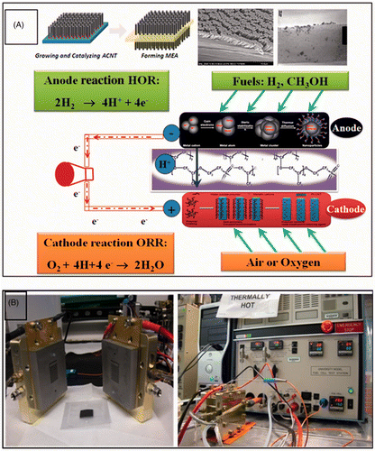
The anodic and cathodic materials were then placed on two sides of the sodium (Na)-form Nafion membrane. Hot pressing technique was then used to construct the MEA under temperature of 210°C and pressure of 600 psig for 5–10 min. The Teflon and glass substrate were then carefully removed from the MEA, which was then impregnated (with cations) in sulphuric acid (H2SO4, 0.5 M) aqueous solution and treated by boiling the solution for 1–2 h, accordingly. The H2SO4 acid treatment aims to exchange ions H+ for Na+ to increase the ionic conductivity. The MEA was then treated in distilled water for 1 h to remove the Na+, Fe2+ and other impurities. The MEA schematic was shown in .
2.3. Nanocharacterisation of Pt-ACNT
The surface morphology, cross-sectional images and the thickness of the ACNTs were determined using a FESEM, equipped with EDS (Department of Chemistry, Texas A&M University-Kingsville). An accelerating voltage of 20 kV and high vacuum of ca 1.0–10−5 mbar were generally employed. The MEA was mechanically fractured using a razor, enabling an easier estimation of the PEMFC catalyst thickness. The Raman spectroscopic analysis was conducted to evaluate the vibration modes and electron structure of Pt and multi-walled nanotubes. Raman and Fourier transform–infrared spectroscopy confocal microscope analysis (FT–IR, Hariba Jobin-Yvon LabRam IR system, Materials Characterisation Facility, Texas A&M University) was employed to obtain highly specific fingerprints to enable the precise chemical and molecular characterisation and identification. The Raman module used was fibre optic coupled with the laser excitation lines at 632 nm with the scanning range of 100–3000 cm−1. The resolution was kept at 0.3 cm−1/pixel at various lines.
2.4. Nanoindentation test of Pt-ACNTs
The elastic modulus and hardness values of Pt-ACNT surfaces were quantified using a Table Top Nanoindentation Tester (TTX-NHT2, CSM Instruments, Needham, MA) with a Berkovich-type diamond indenter. Load-controlled quasi-static method was selected with a maximum force of 10 mN. The tests followed the standard procedure according to ASTM E2546 (30 s loading/unloading). At maximum value, the load signal was also held for 30 s to evaluate the material creep behaviour. In this study, 5–10 indents were performed on each sample to obtain average and consistent data. Due to the ultralow load of this nanoindentation technique, the constitutive structures of ACNT can be accurately measured at very small scales Citation19.
2.5. Electrochemical test of PEMFC device
The ACNT–MEA had an active area of 5 cm2 and was mounted in a single cell for testing with graphite bipolar plates and a single-serpentine flow field. Commercially available carbon cloth treated with Teflon was used as the gas diffusion layer for anode and cathode, and inserted between the MEA and the bipolar plates. The single cell was attached to a test stand (Electrochem Inc.; Chemical Sciences and Engineering, Argonne National Laboratory, Argonne, IL) to record the current–voltage (I–V) polarisation curves Citation20, which gave a measurement of the MEA's performance (). The PEMFC devices were initially conditioned for about 10 h until they reached the desired temperature and humidity conditions, using argon gas in the anode and oxygen gas in the cathode, at a constant voltage of 0.4 V, according to the US Fuel Cell Council test protocol. After a constant current was reached, the polarisation curves were measured by potentiostatically cycling the voltage between 0.2 and 1.0 V. All tests were conducted at a cell temperature of 75°C with hydrogen gas in the anode and air or oxygen gas in the cathode, both gases at relative humidity of 100%. The gas flow rates are 100 mL/min at 1.2 bar and 300 mL/min at 1.5 bar for the anode and cathode, respectively.
3. Results and discussion
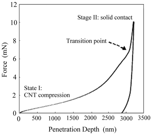
This study indicates that highly ACNTs, when used as PEMFC catalyst, allow for novel structure to be created, which channel gas diffusion through Pt-functionalised ACNT array. This enhances the chemisorption of the gas reactants and promotes properties of PEMFC device. ACNT hydrophobicity also provides a new tool to prevent cathode flooding, resulting in long-term stability of PEMFCs. The nanoindentation result illustrated distinct transition from the beginning of ACNT compression/crushing towards the solid contact.
3.1. Nanocharacterisation of PEMFC device
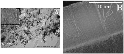
SEM analyses were employed to understand the morphology and dispersion of Pt-modified carbon nanotubes due to the important role of MEA microstructure in the performance and the stability of the electrocatalyst. From the SEM image, it can be seen that MEA displays unique aligned structure of carbon nanotubes with Pt deposition on their surfaces (), which allows for fast gas diffusion through cathodic materials and chemisorbed on the surface of the catalyst. This ensures that mass transfer is not the rate limiting step (RLS), but that electron transfer is RLS. Consequently, MEA kinetics was enhanced. The diameter of the ACNTs is 5–20 nm and from 10 to 30 µm depending on the different growth time period and reactant flow rate.
Figure 2. The SEM morphological image of Pt-functionalised ACNT and carbon nanotubes: (A) the Pt-ACNT, insert: the top-down image of MEA and (B) the cross-sectional image of ACNT.
Raman spectroscopy provides a powerful tool to characterise one-dimensional ACNTs and spectra for various Raman active modes are tabulated in . From the spectra of three selected ACNT (), it can be seen that the orderly arranged structure of the ACNT contributes significantly to its unique optical and spectroscopic properties, due to the one-dimensional confinement. Various features of the ACNT correspond strongly to the vibration modes. The radial breathing mode (RBM) occurs at 212.15–225.56 cm−1, resulting from the symmetric in-phase arrangement of carbon atoms sp2 hybridisation in the ACNT. At the frequency of 1330.00 cm−1, the vibration is classified as the D mode, resulting from a defect-induced second-order feature. At 1584.17 cm−1, a G−-band occurs and at 1759.28 cm−1 M mode occurs, respectively. At high frequency of 2662.59 cm−1, G′ mode vibration is also detected. The Pt metal displays two characteristic modes at frequency of 483 and 2085 cm−1, respectively. Some satellite spectra were also seen due to the complexity of the MEA elemental composition and structure. Most importantly, the mode frequency of ACNT and Pt (inferred from the literature and our preliminary tests) depends on the laser excitation and the dimensional confinement.
Figure 3. The Raman spectroscopic analysis of Pt-functionalised ACNT: (A) Raman spectra for three selected MEA and (B) zoomed-in Raman spectra.
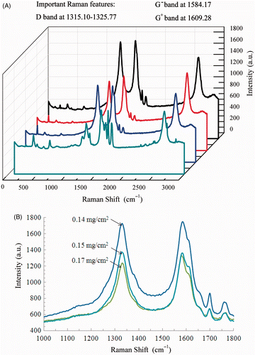
Table 1. The summary of Raman active modes of various vibration bands of Pt-ACNT.
3.2. Nanoindentation test of Pt-ACNT
shows a force–penetration depth curve of nanoindentation performed on ACNT specimen. It was found that there were different stages during the loading process. When contacting with the surface, the indenter tip started to compress the carbon nanotubes vertically, shown in stage I (defined as compression stage). As it was a compression process, the load increment was increased gradually and steadily in order to penetrate deeper into the surface. Once reaching the transition point indicated in , the compression of ACNT reached its limit and solid contaction started, which resulted in a sudden increase of the loading slope in stage II (defined as indentation stage). This observation showed that a higher load was needed to keep indenting into the ACNT when the compression stage was completed. From the unloading curves, the average modulus and hardness of ACNT were calculated to be 6.6 ± 0.6 GPa and 39 ± 4 MPa, respectively. These results indicate that the surface mechanical properties of the Pt-ACNT surface can be improved (when compared to our initial prototypes) and optimised to ensure the long-term stability of the PEMFC devices.
3.3. Electrochemical tests of PEMFC device
The electrochemical performance of the single PEMFC under various cell operating conditions was systematically evaluated. The open circuit potential and current density were measured and used for the power density determination.
3.3.1. Conditioning of single PEMFC
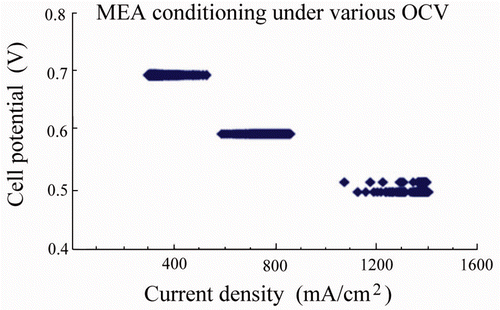
The PEMFCs were conditioned for 10 h to obtain stabilised kinetics. Briefly, the conditioning variables (such as polarisation voltage and operating temperatures) were controlled under flow rate of 100 mL/min for H2 and 300 mL/min for O2. Cell temperature was maintained at 75°C. In this study, the cell potential was kept at a constant value of 0.512, 0.597 and 0.699 V (each measurement was undertaken separately) to ensure the polarisation under low direct current. The plot of cell potential as a function of current density is shown in . It can be seen that the cell performance was enhanced upon the conditioning and reached constant current density after 8–10 h according to the various PEMFC specimens. The novelty of this approach is the unique structure of ACNTs, has catalytic supports which allow for an improved performance due to rapid gas diffusion and chemisorption of the gas reactants. ACNT hydrophobicity also provides a new tool to prevent cathode flooding, resulting in long-term device stability.
3.3.2. Electrochemical behaviour of single PEMFC
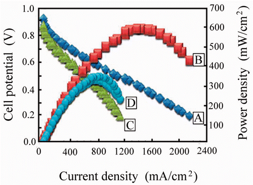
The PEMFC kinetics () were evaluated using current density averaged at 2500 mA/cm2 (), when O2 was used, which exhibit a maximum power density of 720 mW/cm2 (). Whereas air is used as oxidant, the current density () and power density () are determined to be 1500 mA/cm2 and 350 mW/cm2, respectively. In both circumstances, the open circuit voltage is measured to be 0.937–0.997 V. The PEMFC output is critical when it is used to power electronic apparatus. The power density can be calculated using the multiplication of potential by its associated current density. Usually, the PEMFC device does not operate at maximum current density due to the ohmic and concentration losses. The ohmic loss results from the internal resistance and the latter is caused by depletion of the reactants. In our study, the fuel (H2) and oxidant (O2 or air) were controlled at constant flow rate. Therefore, the concentration effect can be negligible.
4. Conclusions
The Pt-ACNT cathodic catalyst was obtained by the CVD, colloidal chemistry impregnation, and followed by heat treatment at 300°C. The catalyst was characterised through SEM and Raman spectroscopy to determine the unique structure and molecular interaction between C and Pt atoms. The results show that the dense ACNT layers have been directly grown on cathode materials with highly aligned structure, which favours gas diffusion. The diameter range of the ACNTs was 5–20 nm and their length range 10–30 µm depending on the growth time period. The Pt nanoparticles are uniformly distributed on the surface of ACNT, and the particle size ranges from 2 to 4 nm. The single PEMFC displayed a maximum power density 720 and 350 mW/cm2 with O2 and air introduced as the oxidant into the cathode, respectively.
Acknowledgements
The authors are grateful to the National Science Foundation Center of Research Education in Science and Technology (HRD-0734850) at the Texas A&M University-Kingsville and the support from United State Department of Energy, the Office of Science and the Divisions of Educational Programs and Chemical Science and Engineering is also duly acknowledged. They are also thankful to the assistance and support from the fuel cell group members at Argonne National Laboratory. The use of TAMU Materials Characterisation Facility and Dr Liang and Dr Young's suggestion and discussion are acknowledged. Dr Linda Washington (the former program coordinator of Faculty and Student Team (FaST) from the Argonne National Laboratory) is specifically acknowledged for her dedication to promote faculty and students to engage in the Science, Technology, Engineering and Mathematics. This study for a special issue is dedicated to the Nanotech 2010. Finally, Dr Thomas Hays (TAMUK) is acknowledged for his discussion regarding the manuscript and copy-editing assistance.
This article was originally published with errors. This version has been corrected. P lease see Erratum (http://dx.doi.org/10.1080/17458080.2013.829704).
References
- Cooper , H W . 2007 . Fuel cells, the hydrogen economy, you and your company . Chem. Eng. Prog. , 103 : 24 – 32 .
- P. Denholm, The role of energy storage in the modern low-carbon grid, National Renewable Energy Laboratory. A talk can be accessed at url: http://www.nrel.gov/analysis/seminar/docs/2008/ea_seminar_june_12.ppt, 2008
- D. Rastler, Hydrogen briefing to the Department of Energy, Electric Power Research Institute. A talk can be accessed at url: http://www1.eere.energy.gov/hydrogenandfuelcells/pdfs/epri_h2_market_study.pdf 2008
- Bruijn , F , Dam , V AT and Janssen , G JM . 2008 . Review: Durability and degradation issues of PEM fuel cell components . Fuel Cells , 8 : 3 – 22 . doi: 10.1002/fuce.200700053
- O' La , G J , In , H J , Crumlin , E , Barbastathis , G and Shao-Horn , Y . 2007 . Recent advances in microdevices for electrochemical energy conversion and storage . Int. J. Energy Res. , 31 : 548 – 575 . doi: 10.1002/er.1280
- Stumper , J and Stone , C . 2008 . Recent advances in fuel cell technology at Ballard . J. Power Sources , 176 : 468 – 476 . doi: 10.1016/j.jpowsour.2007.08.071
- Ahluwalia , R K and Wang , X . 2008 . Fuel cell systems for transportation: Status and trends . J. Power Sources , 177 : 167 – 176 . doi: 10.1016/j.jpowsour.2007.10.026
- Wee , J H . 2007 . Applications of proton exchange membrane fuel cell systems . Renewable Sustainable Energy Rev. , 11 : 1720 – 1738 . doi: 10.1016/j.rser.2006.01.005
- Alcaide , F , Cabot , P -L and Brillas , E . 2006 . Fuel cells for chemicals and energy cogeneration . J. Power Sources , 153 : 47 – 60 . doi: 10.1016/j.jpowsour.2005.11.041
- Barbir , F and Yazici , S . 2008 . Status and development of PEM fuel cell technology . Int. J. Energy Res. , 32 : 369 – 378 . doi: 10.1002/er.1371
- Jagur-Grodzinski , J . 2007 . Polymeric materials for fuel cells: Concise review of recent studies . Polym. Adv. Technol. , 18 : 785 – 799 . doi: 10.1002/pat.935
- Chu , H S , Tsau , F , Yan , Y Y , Hsueh , K L and Chen , F L . 2008 . The development of a small PEMFC combined heat and power system . J. Power Sources , 176 : 499 – 514 . doi: 10.1016/j.jpowsour.2007.08.072
- Ogden , J M , Steinbugler , M M and Kreutz , T G . 1999 . A comparison of hydrogen, methanol and gasoline as fuels for fuel cell vehicles: Implications for vehicle design and infrastructure development . J. Power Sources , 79 : 143 – 168 . doi: 10.1016/S0378-7753(99)00057-9
- Morse , J D . 2007 . Micro-fuel cell power sources . Int. J. Energy Res. , 31 : 576 – 602 . doi: 10.1002/er.1281
- Granovskii , M , Dincer , I and Rosen , M A . 2006 . Economic and environmental comparison of conventional, hybrid, electric and hydrogen fuel cell vehicles . J. Power Sources , 159 : 1186 – 1193 . doi: 10.1016/j.jpowsour.2005.11.086
- Karden , E , Ploumen , S , Fricke , B , Miller , T and Snyder , K . 2007 . Energy storage devices for future hybrid electric vehicles . J. Power Sources , 168 : 2 – 11 . doi: 10.1016/j.jpowsour.2006.10.090
- Jagur-Grodzinski , J . 2007 . Polymeric materials for fuel cells: Concise review of recent studies . Polym. Adv. Technol. , 18 : 785 – 799 . doi: 10.1002/pat.935
- Liu , D -J. , Yang , J , Kariuki , N , Goenaga , G , Call , A and Myers , D . 2008 . Performance improvement in PEMFC using aligned carbon nanotubes as electrode catalyst support . ECS Trans. , 16 ( 2 ) : 1123 – 1129 . doi: 10.1149/1.2981954
- Liu , L , Cao , G and Chen , X . 2008 . Mechanisms of nanoindentation on multiwalled carbon nanotube and nanotube cluster . J. Nanomaterials , 2008 : 1 – 12 .
- Yang , J , Goenaga , G , Call , A and Liu , D -J . 2010 . Polymer electrolyte fuel cell with vertically aligned carbon nanotubes as the electrocatalyst support . Electrochem. Solid-State Lett. , 6 : B55 – B57 . doi: 10.1149/1.3360901
