Abstract
Titanium dioxide nanotube (TNT) films were prepared by pulsed laser deposition (PLD) of P25 and P90 TiO2 nanoparticles onto stainless steel foils followed by a hydrothermal treatment (HT). Heating the PLD films in a TNT precursor solution at 150°C resulted in a well-adhered dense mat of TNTs that were ∼10 nm in diameter with a pore size of ∼4 nm. The TiO2 nanotube films were characterised by SEM, TEM, XRD and Raman spectroscopy.
1. Introduction
Titanium dioxide (TiO2) is a semiconductor material that has received considerable attention due to its electro-optical properties, low cost, and wide availability. There is growing interest in photocatalytic and photovoltaic applications using TiO2 nanoparticle films Citation1. The TiO2 particle size and morphology plays a fundamental role in charge separation where high aspect ratio nanoparticles are preferred. One approach to achieve high aspect ratio nanoparticles involves usage of a mesoporous film as a template from which TiCl4 can be hydrolysed and crystallized into TiO2 nanofibres. By coating a glass substrate with Dallas Amorphous Material-1 (DAM-1) a film of TiO2 fibres was formed Citation2. Other approaches for TiO2 nanofibre arrays include H2/N2 etching of rutile crystals at 700°C Citation3, electrospinning Citation4,Citation5, and by oxidation of titanium substrates under an oxygen atmosphere Citation6. Titanium oxide nanorod films have been obtained by metal organic chemical vapour deposition (MOCVD) Citation7 and oxidation of titanium substrates with acetone at 850°C Citation6 acid vapour oxidation Citation8 and by hydrothermal treatment Citation9. Titanium dioxide nanotubes (TNT) have also been prepared as thin films. One of the first methods reported for preparing TNT films was anodic oxidation Citation10. In this case, a titanium nanotube array was obtained by electrochemical deposition from a TiCl3 solution. TiO2 nanotubes with diameters ranging from 70–100 nm and a length of ∼8 µm were obtained on top of a poly(methyl methacrylate) (PMMA) mould Citation11. Using a similar approach, a voltage (10–40 V) was applied to Ti foil in the presence of fluoride ions to form arrays of TiO2 tubes with diameters of 25–60 nm and tube lengths from 250 nm to 134 µm Citation12–15. Free standing films of oriented TiO2 nanotubes were also achieved by hydrothermal treatment of titanium foil previously dip coated in a P25 suspension Citation16,Citation17. These films were ∼10 µm thick and the nanotube composition was described as H2Ti3O7 Citation16. The TiO2 nanotube outer diameter was reported to be between 6–10 nm and the inner diameter was 4–6 nm. Finally, TiO2 nanotube films have also been obtained through hydrothermal treatment (HT) of titanium flakes Citation18. These TiO2 nanotubes exhibited outer diameters between 6–8 nm and inner diameters between 4–6 nm Citation17.
While TNT films can be uniform and highly oriented, the tube diameters are generally quite large (25–150 nm) Citation11–15. In contrast, the TNTs prepared by hydrothermal treatment are usually <10 nm diameter with pores ∼3 nm Citation19. It would be desirable to prepare well-adhered TNT films with small diameters and high-surface area. We have previously shown that mesoporous MCM-41 could be fabricated as highly oriented tubule films using pulsed laser deposition (PLD) Citation20. In this case, the PLD film acts as a seed layer and a subsequent hydrothermal treatment reorganises the film. Thus, it may be possible that PLD could facilitate TNT film formation. Anatase or rutile TiO2 thin films have been prepared by PLD Citation21–25. When a sintered (>1000°C) TiO2 target was used, rutile tends to be the dominant phase in the films when using low oxygen pressures (∼10 mTorr) while anatase dominates when using higher oxygen pressures (20–75 mTorr) Citation22,Citation23. Anatase films can also be obtained if the substrate is kept under 700°C and a titanium metal target is used with an O2 pressure of 112 mTorr oxygen atmosphere Citation25. Interestingly, the anatase to rutile transition in PLD films has been reported at substrate temperatures as low as 300°C Citation21. It has also been reported that rutile film formation is favoured at laser repetition rates of 20–40 Hz while anatase is favoured at 50 Hz Citation21. Anatase has been reported as the main product if the PLD film thickness is 50 nm, while at 100 nm and 300 nm rutile is the main product Citation21,Citation24. In this paper we report the formation of well-adhered titanium nanotube films on stainless steel assisted by pulsed laser deposition. The distinct advantage PLD/HT process reported here is that TiO2 seed layers can be coated on many different planar or nonplanar surfaces. The PLD films tend to adhere well to metal and metal oxide surfaces in contrast to spin coated or dip coated films.
2. Experimental section
2.1. Materials
Degussa P25 TiO2 (80% anatase and 20% rutile) and P90 TiO2 (90% anatase and 10% rutile) were supplied by Evonik Degussa Corp. NaOH (97% min) and HCl (37.8%) were purchased from Fisher Scientific. Stainless steel foil (0.05 mm thick, Type 304) was purchased from Alfa Aesar. All chemicals were used without further purification.
2.2. Pulsed laser deposition of P25
First, 2.5 g of Degussa P25 or P90 powder was pressed into a pellet with a diameter of ∼2.5 cm and a thickness ∼3 mm. The P25 (P90) target was mounted inside a stainless steel chamber with controlled atmosphere of ∼200 mTorr of oxygen. The P25 (P90) material was deposited on stainless steel foil (Type 304), positioned ∼3.5 cm away from the target at an angle of ∼40°. The stainless steel foil was heated at 300°C, 400°C, or 500°C using a quartz lamp. The laser deposition was performed for 30 or 60 min. A Lambda Physik Compex 102 excimer laser operating a 248 nm (KrF) was used. Typical experimental conditions were: 300 mJ/pulse, repetition rate 10 Hz, substrate temperature 500°C, oxygen backpressure 200 mTorr, and a deposition time of 60 min. The rate of deposition of the TiO2 films was ∼5 nm/min when using P25 and ∼3.5 nm/min with P90.
2.3. Hydrothermal treatment
After laser ablation, the TiO2 coated stainless steel substrates were positioned vertically in a 40 mL Teflon-lined stainless steel Parr autoclaves, with 30 mL of 10 M NaOH solution. For select samples, an additional 0.5 g of P25 or P90 was added. The samples were heated at 150°C for 3–24 h. The reactors were allowed to cool to room temperature, and then the stainless steel substrates were removed from the NaOH solution and washed with DI water followed by 100 mL of 1 M HCl. Finally the samples were dried overnight at 50°C. Annealed samples were heated at 300°C for 75 min.
2.4. Analysis
Powder X-ray diffraction patterns were obtained using a Rigaku Ultima III X-ray diffractometer using Cu Kα radiation. A Zeiss Supra 40 thermal field emission scanning electron microscope (SEM) was used for SEM imaging. An EDAX-Genesis® standardless method, at 20 keV was used for energy dispersive spectroscopy (EDS) – elemental mapping. Raman spectra were recorded in the region of 100–1000 cm-1 using a Jobin Yvon Horiba high-resolution LabRam Raman microscope system. A Spectra-Physics model 127 helium-neon laser operating at 35 mW of 633 nm output was the excitation source. Transmission electron microscopy (TEM) images were collected using a FEI CM200 FEG transmission electron microscope operating at 200 kV.
3. Results and discussion
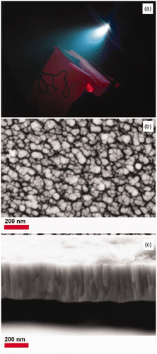
Pressed pellets of Evonik Degussa P25 were irradiated at 248 nm (KrF) using an excimer laser resulting in the blue plume shown in . The resulting TiO2 thin films were deposited on stainless steel foils at 300°C, 400°C, or 500°C. shows a top view SEM image of a PLD TiO2 film after 60 min at 500°C. The average particle size is 55 nm with a minimal amount of splashing. The particle size of P25 is ∼30 nm that suggests some transformation and/or particle agglomeration. The laser ablated film thickness was ∼140 nm for 30 min and ∼310 nm for 60 min. The deposition rate was estimated from cross section images as shown in . The PLD films were also well adhered (tape test). This is one of the advantages of PLD over spin coating or dip coating methods where the TiO2 films are easily removed. This is important for applications where the substrate serves as an electrical contact. The PLD films were largely amorphous (300, 400°C) with the exception of the one weak reflection in the XRD pattern consistent with rutile for the films ablated for 60 min at 500°C (Figure S1). This is not surprising considering the phase dependence on the O2 pressure, substrate temperature and film thickness Citation25.
Figure 1. (Colour online) (a) Digital image of plume from P25 target, (b) SEM image top view and (c) SEM image cross section of TiO2 deposited at 500°C for 60 min.
The TiO2 PLD film functions as a seed layer and requires a hydrothermal treatment to reorganise the film into nanotubes. shows SEM images for samples obtained from PLD films deposited for 30 min and then treated for 3, 5, 10 and 24 h. The TNTs are normally synthesised for 24 h but PLD films of other low density metal oxides tend to reorganise faster Citation26. Unfortunately, synthesis times less than 24 h produced some flower like aggregates or brush-like structures (not shown) but no nanotubes. Similar structures have been reported for titanate nanosheets Citation27 or TiO2/H2Ti5O11·H2O nanocomposites Citation28. Since the density of these nanostructures on the hydrothermally treated films was small the thickness of the PLD layer was increased by ablating for 60 min. After 60 min at 500°C the PLD film thickness increased from ∼140 to ∼310 nm. The PLD films deposited after 60 min were then hydrothermally treated for 24 h as listed in . shows SEM images for the PLD films after hydrothermal treatment for 24 h. The SEM images of sample C4 in show long fibres (2–8 µm) that are 25 nm in diameter along the other particles scattered over the stainless steel foil. While nanofibres form, it may be that the densely packed PLD film does not provide enough TiO2 nanoparticles for the growth of TNTs at a rate comparable to solution. Therefore, the 60 min PLD TiO2 films were hydrothermally treated in a sol–gel that would be the same as for a bulk TNT synthesis, that is, containing P25 nanoparticles. Sample C5 in shows a continuous mat of nanotubes. The resulting nanotube carpet exhibits TNTs with diameters ∼8–11 nm and a film thickness of 1–2 µm. Therefore, the presence of P25 in the gel promotes the formation of titanium nanotubes. To verify the importance of the PLD film, control experiments was run. Figures S2C and S2D shows SEM images of sample C7 that is a blank stainless steel foil heated in the precursor gel. A few TNT spider web deposits can be observed on the stainless steel but they can easily be wiped off. It should also be noted that stainless steel is stable at pH 14 up to 120°C Citation29, such that heating the blank SS foil in 10 M NaOH without P25 at 150°C results in a black magnetite film on the stainless steel (XRD in Figure S1). SEM images of magnetite crystals are shown in Figure S2A and S2B, obtained when stainless steel was hydrothermally treated in 10 M NaOH without any source of TiO2. Interestingly, TiO2 provides a protective coating preventing corrosion. Even the blank stainless steel foil heated in the TiO2 sol–gel does not result in corrosion. This anticorrosion effect of P25 has previously been reported Citation30,Citation31.
Figure 2. SEM images (a and b) for products obtained after hydrothermal treatment with 10 M NaOH of P25 ablated films (Sample C4). Images c and d correspond to PLD film hydrothermally treated in presence of additional P25, (Sample C5) as listed in .
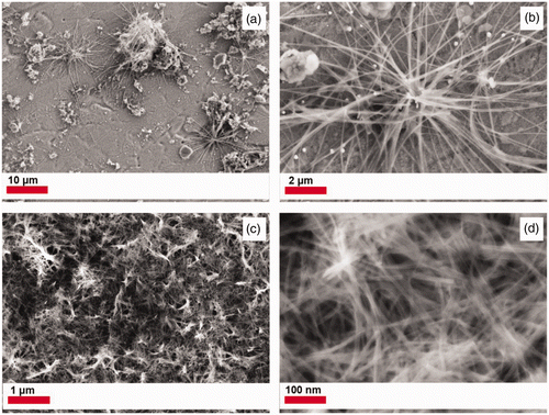
Figure 3. TEM images of titanium nanotubes obtained through the hydrothermal treatment of a PLD film derived from P25 in a 10 M NaOH –P25 solution for (a) and (b) 10 h (sample C9) as listed in .
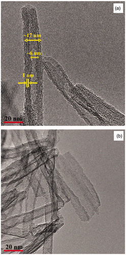
Table 1. Synthesis conditions for TNTs prepared from PLD films deposited after 60 min.
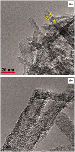
The TNT films were further characterised using transmission electron microscopy (TEM). Heating the film for 10 h (sample C9) results in nanotube formation (). The TEM analysis in confirms that TNTs were formed with an inner diameter of ∼6 nm and outer diameter of ∼17 nm. However, there are also partially rolled nanosheets (). A d-spacing ∼0.25 nm is consistent with partially protonated sodium titanate Citation32,Citation33 versus TiO2-B Citation34 or anatase Citation19. Further heating for 24 h in a TNT precursor solution (Sample C5) results in well-defined nanotubes as shown in the TEM image in . From this TEM image the diameter of the TiO2 nanotubes is 10 nm with a mesopore of 4 nm. This suggests that by increasing the hydrothermal treatment time from 10 to 24 h complete scrolling of the nanosheets was achieved. This also is manifested in a decrease in nanotube pore diameter from ∼6 to ∼4 nm. The TNT surface () also appears to be coated with small nanoparticles which are TiO2 as confirmed by EDAX (TEM) (not shown). shows the TEM image of TNTs from sample C5 after annealing at 300°C. There is no sign of TiO2 nanoparticles on or in the TNTs after heating. This is consistent with the ablated TiO2 nanoparticles being incorporated into the TNTs as it crystallizes and scrolls.
Figure 4. TEM images titanium nanotubes obtained through the hydrothermal treatment of a PLD film in a 10 M NaOH –TiO2 solution for (a) 24 hr-P25 (sample C5) and (b) 24 hr-P25 (sample C5 after annealing at 300°C).
P25 has a particle size of ∼30 nm and a composition of 80% anatase and 20% rutile. In contrast, P90 has a particle size of 13 nm and a composition of 90% anatase and 10% rutile Citation35. The smaller particle size of P90 might result in a more dense PLD film. Therefore, the stainless steel foil was coated by PLD using a P90 target for 60 min at 500°C that results in a PLD film with a thickness of ∼200 nm and particle size of 45 nm. The PLD films were hydrothermally treated using 10 M NaOH with additional P90 in solution for 24 h. The resulting nanotube array, shows a similar morphology to the one obtained by using P25 (vide supra). The SEM image of sample C8 () reveals titanium dioxide nanotubes, with a diameter of ∼10–15 nm. shows the formation of spherical titanium dioxide nanotube agglomerates, 5–10 µm in diameter on top of the nanotube film. The TNT film may promote nucleation of additional titanium dioxide nanoparticles from solution. shows a cross section of the TiO2 nanotube film with a thickness of ∼2 µm.
Figure 5. SEM images of a titanium nanotube array formed by hydrothermal treatment of a PLD derived from P90 film with a 10 M NaOH-P90 solution for 24 h, (see sample C8 in ). (a) and (b) top view, (c) cross section and (d) TEM image of a titanium nanotube from P90 film.
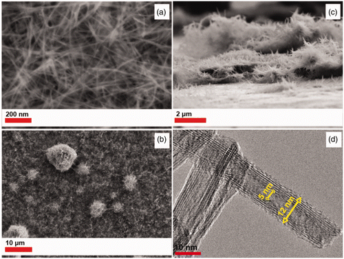
TEM images were obtained for the TNT film synthesised using P90 as shown in . The TiO2 nanotubes that correspond to sample C8, show an inner diameter of 5 nm and an outer diameter or 12 nm. The P25 TNTs decrease in diameter when the hydrothermal treatment time was increased from 10 h (17 nm) to 24 h (10 nm), but there is no significant change after annealing at 300°C. The P90 based TNTs (12 nm) show a slightly bigger nanotube diameter than P25 TNTs (10 nm) when hydrothermally treated for 24 h, and unlike the P25 TNTs the P90 TNTs do not show any occluded TiO2 nanoparticles. The absence of nanoparticles presumably is a consequence of smaller particle size of the P90 precursor and PLD nanoparticles.
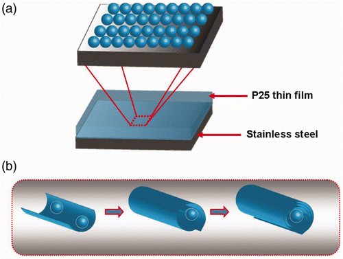
A proposed scheme for the formation of the TNT films is shown in . First TiO2 nanoparticles are deposited by laser ablation over the stainless steel substrate forming a continuous well-adhered film (). Upon exposure to 10 M NaOH at 150°C the TiO2 film particles along with TiO2 particles in solution act as nutrients in the formation of nanosheets (). After 24 h under hydrothermal conditions, the nanosheets scroll into nanotubes forming a TNT array on top of the stainless steel substrate. When P25-based PLD films are used, some TiO2 nanoparticles become attached to the nanosheets and can be observed on the resulting nanotubes. However, the nanoparticles are transformed and incorporated into the crystallized TNT upon annealing at 300°C.
Figure 6. (Colour online) Proposed schemes for titanium nanotube array formation. (a) First, a thin film of TiO2 is deposited through PLD on the stainless steel foil. (b) Second, during hydrothermal treatment the TiO2 nutrients in solution interact with the PLD film forming nanosheets where deposited TiO2 nanoparticles can be trapped in the scrolling TiO2 nanotubes.
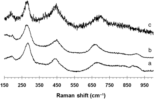
Raman spectra can provide structural helping to identify anatase, rutile, titanate nanotubes, lepidocrocite nanotubes, and restacked titanate nanosheets. According to Gao et al. Citation32,Citation33 titanate nanotubes have Raman bands at 274, 454 and 663 cm−1 corresponding to 3Ag modes. However, for protonic titanate, the 3Ag values shift to 270, 449 and 704 cm−1. The Raman spectra obtained for the titanium nanotubes after 10 h (276, 447, 663, 906 cm−1) () and 24 h (281, 451, 671 and 904 cm−1) () are consistent with the reported values for titanate nanotubes. The band that appears at ∼270–285 cm−1 is very characteristic of the tubular structure and appears to shift with the degree of protonation and radius of curvature Citation36. The bands at 448 cm−1 and 668 cm−1 have been associated with Ti-O-Ti vibrations Citation37. The band at 903 cm−1 has been attributed to a Ti-O-Na vibration Citation38. The presence of Na in the 24 h film (sample C5) was verified by elemental mapping (Figure S3). This indicates that despite multiple washings with acid solution, sodium is present in the titanate nanotubes. After annealing at 300°C, (282, 448 and 700 cm−1) (), the 671 cm−1 band shifts to 700 cm−1, which corresponds to the symmetric Ti-O vibration Citation33. The Raman spectrum for bulk TNTs prepared using a similar precursor solution to the TNT arrays (281, 451, 671 and 904 cm−1). exhibits shifts in the bands at 274 cm−1, 460 cm−1 and 640 cm−1. This likely reflects the higher sodium content in the TNT films. The TNT array formed from P90 (sample C8) exhibits a Raman spectrum with bands at 201, 285, 445 and 635 cm−1 (not shown). This spectrum is consistent with partially protonated sodium titanates. In particular, the protonic lepidocrocite-type titanium dioxide nanotubes show similar Raman spectra (145, 280, 450, 640 and 920 cm−1) Citation39. Some of the differences with P25 based TNTs may arise from the larger tube diameter and pore size. Further experiments to remove the sodium and correlate the Raman spectra with known polytitanic acids are in progress.
4. Conclusions
TiO2 nanotube films were obtained for the first time from P25 and P90 targets by pulsed laser deposition followed by a hydrothermal treatment. Since in both cases the PLD films are initially poorly crystalline rutile, it appears the largest effect of target material is particle size. The TNTs from the larger P25 are covered with ∼1 nm TiO2 particles that are consumed after annealing. This suggests it may be possible to prepare quantum dot decorated TNTs from composite targets. The PLD seeding technique also has the advantage of providing well-adhered TNT films with small diameters and high surface areas that in principle could be adapted to a variety of substrates. It is anticipated that these high aspect ratio and high surface area TNT films will be useful for photovoltaic and photocatalytic applications.
Acknowledgments
We thank the National Science Foundation (CBET 0854059) for financial support.
References
- Xiong , C and Balkus , K J Jr . 2007 . Mesoporous molecular sieve-derived TiO2 nanofibers doped with SnO2 . J. Phys. Chem. C , 111 : 10359 – 10367 .
- Xiong , C and Balkus , K J Jr . 2005 . Fabrication of TiO2 nanofibers from a mesoporous silica film . Chem. Mater. , 17 : 5136 – 5140 .
- Yoo , S , Akbar , S A and Sandhage , K H . 2004 . Nanocarving of bulk titania crystals into oriented arrays of single-crystal nanofibers via reaction with hydrogen-bearing gas . Adv. Mater. , 16 : 260 – 264 .
- Madhugiri , S , Sun , B , Smirniotis , P , Ferraris , J P and Balkus , K J Jr . 2004 . Electrospun mesoporus titanium dioxide fibers . Micropor. Mesopor. Mater. , 69 : 77 – 83 .
- Li , D , Wang , Y and Xia , Y . 2003 . Electrospinning of polymeric and ceramic nanofibers as uniaxially aligned arrays . Nano Lett. , 3 : 1167 – 1171 .
- Peng , X and Chen , A . 2004 . Aligned TiO2 nanorod arrays synthesized by oxidizing titanium with acetone . J. Mater. Chem. , 14 : 2542 – 2548 .
- Wu , J-J and Yu , C-C . 2004 . Aligned TiO2 nanorods and nanowalls . J. Phys. Chem. B , 108 : 3377 – 3379 .
- Yang , X , Zhuang , J , Li , X , Chen , D , Ouyang , G , Mao , Z , Han , Y , He , Z , Liang , C , Wu , M and Yu , J C . 2009 . Hierarchically nanostructured rutile arrays: Acid vapor oxidation growth and tunable morphologies . ACS Nano , 3 : 1212 – 1218 .
- Feng , X , Zhai , J and Jiang , L . 2005 . The fabrication and switchable superhydrophobicity of TiO2 nanorod films . Angew. Chem. Int. Ed. , 44 : 5115 – 5118 .
- Hoyer , P . 1996 . Formation of a titanium dioxide nanotube array . Langmuir , 12 : 1411 – 1413 .
- Hoyer , P . 1996 . Semiconductor nanotube formation by a two-step template process . Adv. Mater. , 8 : 857 – 859 .
- Gong , D , Grimes , C A , Varghese , O K , Hu , W , Singh , R S , Chen , Z and Dickey , E C . 2001 . Titanium oxide nanotube arrays prepared by anodic oxidation . J. Mater. Res. , 16 : 3331 – 3334 .
- Mor , G K , Shankar , K , Paulose , M , Varghese , O K and Grimes , C A . 2005 . Enhanced Photocleavage of water using titania nanotube arrays . Nano Lett. , 5 : 191 – 195 .
- Mor , G K , Varghese , O K , Paulose , M , Ong , K G and Grimes , C A . 2006 . Fabrication of hydrogen sensors with transparent titanium oxide nanotube-array thin films as sensing elements . Thin Solid Films , 496 : 42 – 48 .
- Paulose , M , Shankar , K , Yoriya , S , Prakasam , H E , Varghese , O K , Mor , G K , Latempa , T A , Fitzgerald , A and Grimes , C A . 2006 . Anodic growth of highly ordered TiO2 nanotube arrays to 134 μm in length . J. Phys. Chem. B , 110 : 16179 – 16184 .
- Yang , Y , Wang , X and Li , L . 2008 . Crystallization and phase transition of titanium oxide nanotube arrays . J. Am. Ceramic Soc. , 91 : 632 – 635 .
- Tian , Z R , Voigt , J A , Liu , J , Mckenzie , B and Xu , H . 2003 . Large oriented arrays and continuous films of TiO2-based nanotubes . J. Am. Chem. Soc. , 125 : 12384 – 12385 .
- Guo , Y , Lee , N-H , Oh , H-J , Yoon , C-R , Park , K-S , Jung , S-C and Kim , S-J . 2008 . The growth of oriented titanate nanotube thin film on titanium metal flake . Surf. Coatings Tech. , 202 : 5431 – 5435 .
- Ratanatawanate , C , Xiong , C and Balkus , K J Jr . 2008 . Fabrication of PbS quantum dot doped TiO2 nanotubes . ACS Nano , 2 : 1682 – 1688 .
- Balkus , K J Jr , Scott , A S , Gimon-Kinsel , M E and Blanco , J H . 2000 . Oriented films of mesoporous MCM-41 macroporous tubules via pulsed laser deposition . Micropor. Mesopor. Mater. , 38 : 97 – 105 .
- Inoue , N , Yuasa , H and Okoshi , M . 2002 . TiO2 thin films prepared by PLD for photocatalytic applications . Appl. Surf. Sci. , 197–198 : 393 – 397 .
- Murugesan , S , Kuppusami , P , Parvathavarthini , N and Mohandas , E . 2007 . Pulsed laser deposition of anatase and rutile TiO2 thin films . Surf. Coatings Tech. , 210 : 7713 – 7719 .
- Syarif , D G , Miyashita , A , Yamaki , T , Sumita , T , Choi , Y and Itoh , H . 2002 . Preparation of anatase and rutile thin films by controlling oxygen partial pressure . Appl. Surf. Sci. , 193 : 287 – 292 .
- Nakamura , T , Ichitsubo , T , Matsubara , E , Muramatsu , A , Sato , N and Takahashi , H . 2005 . Preferential formation of anatase in laser-ablated titanium dioxide films . Acta Materialia , 53 : 323 – 329 .
- Xu , Y and Shen , M . 2009 . Anatase TiO2 films fabricated by pulsed laser deposition using Ti target . Appl. Phys. A: Mater. Sci. Proc. , 94 : 275 – 280 .
- Balkus , K J Jr , Munoz , T Jr and Gimon-Kinsel , M E . 1998 . Preparation of Zeolite UTD-1 Films by pulsed laser ablation: Evidence for oriented film growth . Chem. Mater. , 10 : 464 – 466 .
- Peng , C-W , Ke , T-Y , Brohan , L , Richards-Plouet , M , Huang , J-C , Puzenat , E , Chiu , H-T and Lee , C-Y . 2008 . (101)-Exposed anatase TiO2 nanosheets . Chem. Mater. , 20 : 2426 – 2428 .
- Yang , H G and Zeng , H C . 2005 . synthetic architectures of TiO2/H2Ti5O11 · H2O, ZnO/H2Ti5O11 · H2O, ZnO/TiO2/H2Ti5O11 · H2O, and ZnO/TiO2 nanocomposites . J. Am. Chem. Soc. , 127 : 270 – 278 .
- Yasuda , M , Fukumoto , K , Ogata , Y and Hine , F . 1988 . Corrosion behavior of Ni and Ni-based alloys in concentrated NaOH solutions at high temperatures . J. Electrochem. Soc. , 135 : 2982 – 2987 .
- Shen , G X , Chen , Y C and Lin , C J . 2005 . Corrosion protection of 316 L stainless steel by a TiO2 nanoparticle coating prepared by sol-gel method . Thin Solid Films , 489 : 130 – 136 .
- Yun , H , Li , J , Chen , H-B and Lin , C-J . 2007 . A study on the N-, S- and Cl-modified nano-TiO2 coatings for corrosion protection of stainless steel . Electrochim. Acta , 52 : 6679 – 6685 .
- Gao , T , Fjellvåg , H and Norby , P . 2009 . Crystal structures of titanate nanotubes: A raman scattering study . Inorg. Chem. , 48 : 1423 – 1432 .
- Gao , T , Fjellvåg , H and Norby , P . 2008 . Raman scattering properties of a protonic titanate HTi#O•HO (#, vacancy; x = 0.7) with lepidocrocite-type layered structure . J. Phys. Chem. B , 112 : 9400 – 9405 .
- Armstrong , G , Armstrong , A R , Canales , J and Bruce , P G . 2005 . Nanotubes with the TiO2-B structure . Chem. Commun. , 41 : 2454 – 2456 .
- Peiro , A M , Colombo , C , Doyle , G , Nelson , J , Mills , A and Durrant , J R . 2006 . Photochemical reduction of oxygen adsorbed to nanocrystalline TiO2 films: A transient absorption and oxygen scavenging study of different TiO2 preparations . J. Phys. Chem. B , 110 : 23255 – 23263 .
- Qian , L , Du , Z-L , Yang , S-Y and Jin , Z-S . 2005 . Raman study of titania nanotube by soft chemical process . J. Mol. Struct. , 749 : 103 – 107 .
- Bavykin , D V , Friedrich , J M and Walsh , F C . 2006 . Protonated titanates and TiO2 nanostructured materials: Synthesis, properties, and applications . Adv. Mater. , 18 : 2807 – 2824 .
- Cortes-Jacome , M A , Ferrat-Torres , G , Ortiz , L FF , Angeles-Chavez , C , Lopez-Salinas , E , Escobar , J , Mosqueira , M L and Toledo-Antonio , J A . 2007 . In situ thermo-Raman study of titanium oxide nanotubes . Catal. Today , 126 : 248 – 255 .
- Ma , R , Fukuda , K , Sasaki , T , Osada , M and Bando , Y . 2005 . Structural features of titanate nanotubes/nanobelts revealed by Raman, X-ray absorption fine structure and electron diffraction characterizations . J. Phys. Chem. B , 109 : 6210 – 6214 .

