
 ?Mathematical formulae have been encoded as MathML and are displayed in this HTML version using MathJax in order to improve their display. Uncheck the box to turn MathJax off. This feature requires Javascript. Click on a formula to zoom.
ABSTRACT
Thermal performance of energy systems can be improved by adding metal or metal-oxide nanoparticles to a base fluid, thereby increasing heat-transfer efficiency. Laminar pipe flow of a Cu–water nanofluid was studied using discrete phase model numerical simulation and experimental methods. The forces including thermophoretic and Brownian forces were considered to solve the particles governing equation. A two-step method was employed in the preparation of the nanofluid. The influences of Reynolds number, fluid temperature, and particle volume fraction on the flow pressure drop and convective heat-transfer coefficient of the nanofluid have been studied. The results demonstrated that adding nanoparticles to a base fluid significantly enhanced convective heat transfer in a pipe and increased energy loss. The pressure drop increased with increasing Reynolds number. A critical nanoparticle volume fraction existed, beyond which the pressure drop changed from increasing to decreasing with increasing nanoparticle volume fraction. This is attributed to competition between slip of particles on the pipe wall and the effect of a drag force on the particles. The deposition efficiency of nanoparticle changing with the particle size and volume fraction also has been illustrated.
1. Introduction
Many techniques have been proposed to improve heat-transfer performance and achieve more efficient heat-exchange equipment. A classical way to increase heat-transfer efficiency is by adding well-suspended metal or metal-oxide nanoparticles to the base fluid [Citation1–3]. It has become popular to use nanofluids to increase thermal performance in energy systems.
There are many studies related to the subject of flow and heat transfer in pipes filled with nanofluids. Wang et al. [Citation4] studied the flow characteristics of a CuO–water nanofluid in a thin circular tube and showed that the Reynolds number for transformation of turbulent flow, which is proportional to the diameter of tube. Hasan [Citation5] numerically studied flow and heat transfer of a nanofluid, finding that both pressure drop and heat transfer increased when using a nanofluid. Lavasani and Bayat [Citation6] found that the pressure drop from a cam-shaped tube bank was substantially lower than that of a circular tube bank for all ranges of Reynolds number and volume fractions. Wen et al. [Citation7] studied nanofluids in a tube under laminar flow conditions and found that the convective heat-transfer coefficient increased significantly in the region of the fluid inlet section: the extent of heat-transfer enhancement was proportional to the volume concentration of the particles in the fluid. Yang et al. [Citation8] experimentally studied heat transfer properties of nanoparticle in fluid dispersions under laminar flow and found that the convective heat transfer coefficient increased on adding nanofluid to the base fluid: the rate of increase was dependent on temperature.
Vijayakumar et al. [Citation9] experimentally investigated the thermal characteristics of a cylindrical sintered wick heating pipe using CuO and Al2O3 nanofluids and determined that the addition of nanoparticles had a notable influence on the surface temperature of the pipe, which gradually reduced with increasing nanoparticle concentration. Popa et al. [Citation10] reported a similar phenomenon. Esmaeilzadeh et al. [Citation11] experimentally studied characteristics of a γ-Al2O3–water nanofluid through a circular tube, finding that nanofluids exhibited better heat-transfer performance and an increase in the friction factor after adding nanoparticles. Lin et al. [Citation12] investigated boundary layer flow and heat transfer of a copper–water nanofluid driven by exponential temperature with radiation effects. They showed that the solid volume fraction and nanoparticle shape had significant impact on the thermal conductivity and that spherical nanoparticles enhanced heat transfer better than other shapes. Ding et al. [Citation13] studied the heat transfer of a carbon nanotube (CNT)–water nanofluid, concluding that the enhanced heat transfer resulted not only from adding nanoparticles to the working fluid, but was related to the coefficient of thermal conductivity in the shear-induced state. Heris et al. [Citation14] studied CuO–water and Al2O3–water nanofluids in a horizontal circular tube under conditions of laminar flow and uniform wall temperature. Their results showed that convective heat transfer was not only proportional to the volume concentration of the nanofluid, but also to the Reynolds number. Results of Fotukianet al. [Citation15] on similar systems showed that the effect of volume concentration of the nanofluid on the convective heat transfer coefficient could almost be neglected under dilute conditions (vol% <0.24%). These researchers also found that the ratio of the convective heat-transfer coefficients of the nanofluid and base fluid decreased with increase of Reynolds number, which was in contradiction with the results of Pak [Citation16] and Xuan [Citation17]: according to the latter, the pressure drop of the nanofluid was significantly greater than that of the base fluid under dilute conditions. Sajadj et al. [Citation18] studied the TiO–water nanofluid (vol% >0.25%), showing that the pressure drop in a pipe increased with increasing volume concentration of the nanofluid. Zhang et al. [Citation19,Citation20] studied TiO2–water flow and heat characteristics in a minichannel tube. They found that this nanofluid enhanced thermophysical properties, but the pressure drop in the tube increased. The improvement of heat-transfer efficiency correlated well with increasing Reynolds number and volume concentration. Mahdavi et al. [Citation21] compared different multiphase flow models in tube by numerical simulation. They found multiphase flow models were more accurate than the single phase. Lin et al. [Citation22–24] numerical simulated nanofluids flow and heat transfer characteristics concerning cylindrical and rod-like nanoparticles and firstly studied the nanoparticles orientation,coagulation and breakage effects on friction factor and Nusselt number in a pipe flow.
Flow and heat transfer in pipes have many engineering applications, including those of heat exchangers, cooling towers, and heating, ventilation, and air conditioning. Many nanofluid studies have been carried out, especially relating to heat transfer enhancement in pipe flows; however, there has been less study of the associated pressure drop and movement of nanoparticles using multiphase flow models. In this work, experimental method and numerical simulation with discrete phase model (DPM) were used to study Cu–water nanofluid pressure drop and heat transfer in a laminar pipe flow.
2. Numerical method
2.1. Governing equations of continuous phase
It was assumed that the fluid was incompressible, Newtonian and continuous. The fluid flow was calculated based on the Euler approach by solving the governing partial differential equations of mass, momentum and energy, given, respectively, by the following equations:(1)
(1)
(2)
(2)
(3)
(3) where ρ is the fluid density, u is the fluid velocity, p is the pressure, ν is the viscosity at the inlet temperature, T is the temperature, α is the thermal diffusivity and t is the time.
2.2. Governing equations of particles
The particle phase under the following assumptions: (Equation1(1)
(1) )It is assumed that particles are dilute,very small and rigid smooth spheres. Therefore, the force of particles effect on the fluid can be neglected. (Equation2
(2)
(2) ) For DPM, a direct simulation of inter-particle effects is not feasible due to the high computational effort and the large storage requirements with small and large number particles. In order to consider both the precision and efficiency, the inter-particle collision could be ignored concerning particles concentration and size following [Citation25]. (Equation3
(3)
(3) ) The walls are considered as perfectly absorbing, which means if a particle hits a wall it sticks to the surface.
Based on Newton's second law of motion, the governing equations of motion for the particles in two-phase flow are given by:(4)
(4) where mp and Vp are the mass and volume of the particle respectively, ρp is the density of the particles being 1225 kg/m3, up is the particle velocity, FD is the drag forces, FB is Brownian forces and FT is the thermophoresis force.
Expression of the drag forces is(5)
(5) Here dp is the diameter of the particle, μ is the dynamic viscosity, Cc is Cunningham correction factor which can be derived as a function of the size of the particle and the properties of the fluid. The expression is depend on the Knudsen number Kn. When the particle size is in the transfer processes region (0.06 < Kn < 10), the slip correction factor has the following expression:
(6)
(6) Brownian force is the major consequence of random motion and collisions with the carrier fluid molecules, which affects particle motion.The Brownian force can be expressed as
(7)
(7) where K is the Boltzmann constant, K = 1.381 × 10⁻²³ J/K. Δt is the magnitude of time step. ξ0 is a zero mean variant from a Gaussian probability density function. The random direction of the Brownian force is accounted for by evaluating both the x, y and z components of FB at each time step using independent values of ξ0 in the three directions.
Besides Brownian force, thermophoretic force can be caused by temperature gradients, which are strongly influenced by the particles’ diffusion. In this numerical simulation the thermophoretic force can be expressed as [Citation26](8)
(8) where C and Cp = 380 J/(kg·K) are the specific heat of water and particle, respectively.
After solving the governing equations, the local Nusselt number is defined as(9)
(9) The average Nusselt number (Nu) is obtained by integrating the local Nusselt number (Nux) over the pipe length (L) as follows:
(10)
(10)
2.3. Geometric models
A schematic of the physical configuration of the case is shown in . It comprised a three-dimensional model with a pipe length L = 100d, d is the pipe diameter. The velocity inlet boundary condition is defined by the temperature, velocity and particle number, as specified at the inlet. The outflow boundary condition is applied to the outlet and a no-slip boundary condition is defined for the wall, which is at constant temperature. The flow state is laminar.
Figure 1. Schematic of physical model.
The governing equations are converted into algebraic equations using the finite volume method. The convective and diffusion terms are discretized to second-order accuracy. The SIMPLE algorithm is adopted to couple the pressure and velocity fields.
The particles’ parameters such as diameter,density and mass flow rate can be set in the inlet surface of pipe. All the particles in each computational cell are divided into a number of groups, called parcels, and one particle in each parcel represents all the particles in that parcel. There are 820 grids in this surface which means that computational parcel number is 820,but the realistic number of particle is computed using the parcel and the rate of mass flow according the nanofluid concentration.
3. Experimental method
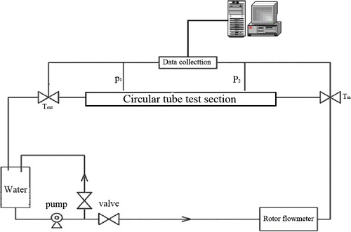
Flow experiments were performed to validate the simulation results. The experimental test system is depicted schematically in . A pump generated power for the fluid cycle and a valve regulated the flow rate against further changes in the velocity in the pipe. The flow rate of the fluid was measured using a rotameter; pressure and temperature data were acquired by piezoelectric transducer and thermocouple temperature transducer, respectively. All experiments were carried out at the temperature of 293 K.
Figure 2. Schematic of experiment set-up.
In this study, Cu nanoparticles (Beijing Dedao New Material Company, China) with an average diameter 50 nm were used. shows a transmission electron micrograph of the nanoparticles, confirming their spherical shape. Fixed quantities of Cu nanoparticles at different volume concentrations were dispersed in pure deionized water using a two-step method. Sample preparation was carried out using a mass balance with an accuracy of 0.1 mg. The volume fraction of the powder was calculated from the mass of dry powder using the true density provided by the supplier and the total volume of the suspension. The nanofluid mixture was stirred continuously and sonicated for 3 h to ensure uniform dispersion of the nanoparticles in the base fluid.
Figure 3. TEM image of Cu nanoparticles.
4. Results and discussion
4.1. Numerical validation
shows the influence of mesh number on the simulation of Nusselt numbers in the heat-transfer processes using both the base fluid and nanofluid as media. With the increase of mesh quantity, the variation in Nusselt number decreased and the simulation results tended to stabilize. When the mesh was in the range of 1 million to 2 million, the effect of mesh quantity on the simulated results became infinitesimally small and could be neglected. A mesh quantity of 1,515,415 was used in these simulations.
Table 1. Validation of mesh quantity.
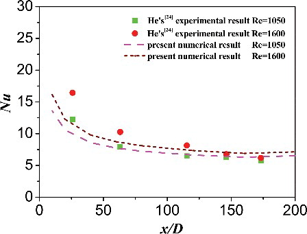
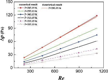
Mechanical energy in flow losses within horizontal internal pipe flows will induce a pressure drop when the velocity is kept constant. According to Newton's viscosity fiction law, for fully developed pipe laminar flow, the pressure drop (Δp) is given by Δp = 64ρReu2/d3. When the physical characteristics of the fluid and pipe diameter are kept constant, the increase in pressure drop with Reynolds number is linear. To ensure that the numerical method was accurate for solving flow and heat transfer processes in a pipe, the pressure drop and heat transfer were calculated and the results compared with both theoretical and experimental results. shows that the pressure drop in a pipe changed with the Reynolds number. compares the Nusselt numbers obtained from this numerical result with those of He's experimental results [Citation27] at an inlet flow temperature of 295 K and constant heat flux of 4000 W/m2. The numerical results were coincident with these previous results, indicating validity of the numerical simulation.
Figure 4. Effect of Reynolds number on pressure drop.
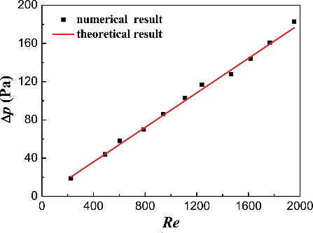
Figure 5. Nu distribution along the axial.
4.2. Effect of nanoparticles on pressure drop
shows the effect of inlet Reynolds number on the pressure drop of the base liquid for inlet temperatures ranging from 285.15 to 353.15 K. The pressure drop in the pipe increases with an increasing of Reynolds number from 300 to 1200. At the same time, the pressure drop in the pipe is obviously affected by the inlet temperature: as the inlet fluid temperature increasing, the fluid viscosity decreases, inducing a reduction in Newton's viscosity fiction force. As a result, the pressure drop in the pipe decreases with an increase in the flow temperature.
Figure 6. The based fluid pressure drop changes with Reynolds number and temperature.
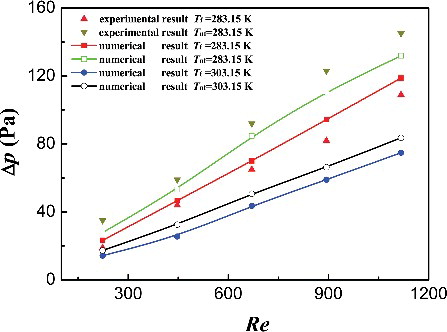
shows the effect of inlet velocity on pressure drop for a nanofluid of 50 nm particles and 1% volume fraction at inlet fluid temperatures of 283.15 and 303.15 K. Comparing the Cu nanofluid with the base fluid, both experimental and simulation results showed that the pressure drop increased significantly after adding copper nanoparticles to the base fluid. Therefore, the effects of Reynolds number and temperature on the pressure drop are coincident for this nanofluid and the water-based fluid in a pipe. With increasing Reynolds number and decreasing temperature, the pressure drop increased.
Figure 7. Pressure drop comparing nanofluid and base liquid.
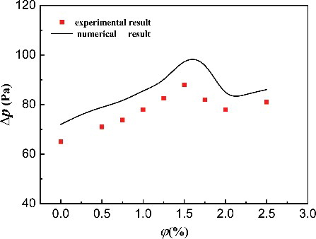
The effect on the pressure drop of adding different volume concentrations of Cu nanoparticle to pure water has been investigated. shows the effect of the volume fraction of nanoparticles ϕ from 0.2% to 2.5% on pressure drop with a Reynolds number of 1787 and inlet temperature of 293.15 K, where ϕ = 0 represents the base liquid. It is clear that the pressure drop is larger when using the nanofluid. Adding nanoparticles from 0% to 1.5% volume concentration to pure water results in 0%–36% increment in the pressure drop; however, when the volume concentration of Cu nanoparticles exceeded 1.5%, the pressure drop is less than when using lower concentrations. shows that the volume fraction of nanofluid has a complex effect on the pressure drop. For lower volume fractions of nanofluid, the pressure drop increases with increasing nanoparticle concentration, and inducing a rising drag force. As the nanoparticle concentration in the fluid increased, there are more particles in the boundary layer near the pipe wall; some of these particles move along the wall by slippage, leading to diminishing frictional resistance. Competition between particles slipping and the drag force on the particles led to the pressure drop first increasing and then decreasing with increasing particle concentration. Pressure drop of a nanofluid flowing in a pipe depended both on the nanoparticle concentration and on movement of particles near the pipe wall. The discrepancy between the numerical results and experimental ones is because the dynamic of nanoparticles is very complicated which DPM doesn't consider the processes such as collision, coagulation, breakage, etc. But DPM simulation results show that there is a reasonable trend for volume fraction of nanoparticles on pressure drop.
Figure 8. The effect of volume fraction of nanofluid on pressure drop.
4.3. Effect of nanoparticles on heat-transfer characteristics
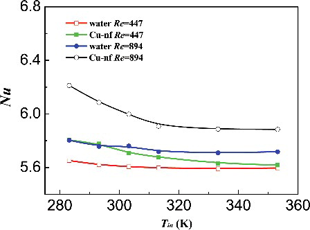
The average Nusselt numbers for the base fluid and nanofluid are shown in . On adding nanoparticles to the base fluid, the average Nusselt number of the nanofluid Nunf is 3.14% larger than that of the base fluid for an inlet fluid temperature of 283.15 K. Similar to the effect in pure water, the average Nusselt number of the nanofluid is obviously affected by the Reynolds number, and increases with increasing Reynolds number. When the inlet temperature increases to 303.15 K, the average Nusselt numbers of both the nanofluid and pure water decrease because of the changes in the physical parameters of the fluid, such as viscosity and thermal diffusivity. Detailed results concerning changes in average Nusselt number in pipe flow with different inlet temperatures are shown in . Because Brownian movement and thermophoresis of nanoparticles are influenced by temperature, the average Nusselt number of the nanofluid is more affected by inlet temperature than the base fluid. Overall, the inlet temperature slightly affected the heat transfer process for both liquids.
Figure 9. The comparison of Nu between water and nanofluid.
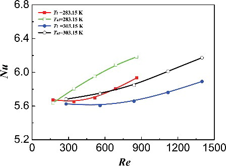
Figure 10. The effect of fluid inlet temperature on Nu.
shows the average Nusselt number changes with different volume fractions of nanofluid from 0.2% to 2.5% at Re = 300. Adding a small fraction of nanofluid enhanced heat transfer. With an increasing of nanoparticle volume concentration, the heat transfer is constantly improved.
Figure 11. The effect of nanoparticle volume fraction on Nu.
Using a nanofluid as the working fluid can increase heat transfer. Choosing a suitable nanoparticle volume fraction can decrease pressure drop in pipe flow. This represents an effective method of energy conservation.
4.4. Nanoparticle deposition in the flow
Nanoparticles deposited on the wall can cause wall fouling and heat transfer performance decline. In this study, the Brownian and thermophoretic forces usually affect the particles deposition. Therefore, the deposition characteristic of nanoparticles in the nanofluid pipe flow is numerically investigated with DPM method.
The deposition efficiency (η) is computed for different particle diameter using the following equation:(11)
(11) Here
is the number of particle that deposited in the wall and
is the number of particle which entered the pipe.
shows the nanoparticles deposition efficiency changing with particle size and particle volume fraction, which Re is equal to 894 and the temperature of flow and wall are 20 and 50 °C, respectively. Because of the direction of thermophoretic force is oppositely to the wall, the thermophoretic force will prevent the nanoparticle deposition. With the effect of Brownian force, gravity and thermophoretic force, the deposition efficiency of nanoparticle increases with decreasing of the particle size and growth of particle volume fraction.
Figure 12. Numerical results of nanoparticle deposition versus (a) particle size (b) nanoparticle volume fraction.
5. Conclusions
In this work, numerical simulation and experimental methods have been used to study Cu–water nanofluid under different flow conditions in a horizontal pipe. The key findings are as follows:
| (1) | Pressure drop of the pipe flow increases obviously after adding copper nanoparticles to the base fluid. The Reynolds number, fluid temperature and nanoparticle fraction affect the energy loss of the nanofluid pipe flow. | ||||
| (2) | Competition between particles moving by slip and the drag force on particles results in a complex relationship between pressure drop and particle concentration; the trend is not linear. | ||||
| (3) | When the volume fraction of nanoparticles is below 2.5%, use of a nanofluid as the working fluid increased heat transfer; with increasing nanoparticle volume concentration, the strengthen of the heat transfer constantly increased. | ||||
| (4) | The nanoparticles deposition efficiency increases with decreasing of the particle size and growth of particle volume fraction. | ||||
Disclosure statement
No potential conflict of interest was reported by the authors.
Additional information
Funding
Reference
- Chen YJ, Wang PY, Liu ZH. Numerical study of natural convection characteristics of nanofluids in an enclosure using multiphase model. Heat Mass Transf. 2016;52(11):2471–2484.
- Ellahi R, Hassan M, Zeeshan A. A study of heat transfer in power law nanofluid. Therm Sci. 2016;20(6):2015–2026.
- Chol SUS. Enhancing thermal conductivity of fluids with nanoparticles. ASME Publ Fed. 1995;231:99–106.
- Wang X, Xu XS, Choi SU. Thermal conductivity of nanoparticle-fluid mixture. J Thermophys Heat Transf. 1999;13(4):474–480.
- Hasan MI. Investigation of flow and heat transfer characteristics in micro pin fin heat sink with nanofluid. Appl Therm Eng. 2014;63(2):598–607.
- Lavasani AM, Bayat H. Numerical study of pressure drop and heat transfer from circular and cam-shaped tube bank in cross-flow of nanofluid. Energy Convers Manag. 2016;129:319–328.
- Wen D, Ding Y. Experimental investigation into convective heat transfer of nanofluids at the entrance region under laminar flow conditions. Int J Heat Mass Transf. 2004;47(24):5181–5188.
- Yang Y, Zhang ZG, Grulke EA, et al. Heat transfer properties of nanoparticle-in-fluid dispersions (nanofluids) in laminar flow. Int J Heat Mass Transf. 2005;48(6):1107–1116.
- Vijayakumar M, Navaneethakrishnan P, Kumaresan G. Thermal characteristics studies on sintered wick heat pipe using CuO and Al2O3 nanofluids. Exp Therm Fluid Sci. 2016;79:25–35.
- Popa CV, Nguyen CT, Gherasim I. New specific heat data for Al2O3 and CuO nanoparticles in suspension in water and Ethylene Glycol. Int J Therm Sci. 2017;111:108–115.
- Esmaeilzadeh E, Almohammadi H, Nokhosteen A, et al. Study on heat transfer and friction factor characteristics of γ-Al 2 O 3/water through circular tube with twisted tape inserts with different thicknesses, Int J Therm Sci. 2014;82:72–83.
- Lin Y, Li B, Zheng L, et al. Particle shape and radiation effects on Marangoni boundary layer flow and heat transfer of copper-water nanofluid driven by an exponential temperature. Powder Technol. 2016;301:379–386.
- Lin Y, Li B, Zheng L, et al. Heat transfer of aqueous suspensions of carbon nanotubes (CNT nanofluids). Int J Heat Mass Transf. 2006;49(1):240–250.
- Heris SZ, Etemad SG, Esfahany MN. Experimental investigation of oxide nanofluids laminar flow convective heat transfer. Int Commun Heat Mass Transf. 2006;33(4):529–535.
- Fotukian SM, Esfahany MN. Experimental study of turbulent convective heat transfer and pressure drop of dilute CuO/water nanofluid inside a circular tube. Int Commun Heat Mass Transf. 2010;37(2):214–219.
- Pak BC, Cho YI. Hydrodynamic and heat transfer study of dispersed fluids with submicron metallic oxide particles. Exp Heat Transf. 1998;11(2):151–170.
- Xuan YM, Hu WF, Li Q. Simulations of Structure and Thermal Conductivity of Nanofluids. J Eng Thermophys. 2002;23(2): 206–208.
- Sajadi AR, Kazemi MH. Investigation of turbulent convective heat transfer and pressure drop of TiO2/water nanofluid in circular tube. Int Commun Heat Mass Transf. 2011;38(10): 1474–1478.
- Zhang J, Diao Y, Zhao Y, et al. An experimental investigation of heat transfer enhancement in minichannel: combination of nanofluid and micro fin structure techniques. Exp Therm Fluid Sci. 2017;81:21–32.
- Zhang J, Diao Y, Zhao Y, et al. Experimental study of TiO2–water nanofluid flow and heat transfer characteristics in a multiport minichannel flat tube. Int J Heat Mass Transf. 2014;79:628–638.
- Mahdavi M, Sharifpur M, Meyer JP. Simulation study of convective and hydrodynamic turbulent nanofluids by turbulence models. Int J Therm Sci. 2016;110:36–51.
- Lin JZ, Xia Y, Ku XK. Friction factor and heat transfer of nanofluids containing cylindrical nanoparticles in laminar pipe flow. J Appl Phys. 2014;116:133513.
- Lin JZ, Xia Y, Ku XK. Pressure drop and heat transfer of nanofluid in turbulent pipe flow considering particle coagulation and breakage. J Heat Transf. 2014;136(11):111701.1–111701.9.
- Lin JZ, Xia Y, Ku XK. Flow and heat transfer characteristics of nanofluids containing rod-like particles in a turbulent pipe flow. Int J Heat Mass Transf. 2016;93:57–66.
- Sommerfeld M. Validation of a stochastic Lagrangian modelling approach for inter-particle collisions in homogeneous isotropic turbulence. Int J Multiph Flow. 2001;27(10):1829–1858.
- Talbot L, Cheng RK, Chefer RW, et al. Thermophoresis of particles in a heated boundary layer. J Fluid Mech. 1980;101(4):737–758.
- He YR, Han JC. Investigation of flow and convective heat transfer of Al2O3/H2O nanofluids in tube with numerical simulation. The 15th national conference on composite materials academic (part ii). Harbin Institute of Technology; Harbin. 2008.