
Abstract
In this research, a one step, facile route has been undertaken to synthesise copper oxide/reduced graphene oxide (CuO/rGO) nanocomposites. X-ray powder diffraction analysis (XRD) was carried out to identity the crystalline structure and phase of the synthesised sample. Elemental analysis and surface morphological features were analysed using EDX and FESEM Images. Particle size as well as the shape of the as prepared composite was observed from HR-TEM images. Raman spectra illustrated the peak of the individual composite materials. The electrochemical properties of the prepared nanocomposite were investigated. The dielectric behaviour of the sample including dielectric constant, dielectric loss and AC conductivity was measured at various frequency levels. Temperature was varied accordingly to observe the effect of temperature on the dielectric properties of the sample.
1. Introduction
Graphene is a comparatively new form of nano carbon where monolayers of carbon atoms are arranged in a honeycomb lattice. It has attracted huge attention in recent years among the experimental and theoretical scientific communities [Citation1]. Graphene oxide (GO) is one of the most important derivatives of graphene. GO exhibit layered structure where oxygen functional groups are present on its basal planes and edges [Citation2]. Since it has special surface properties and layered structure, it can be considered as potential nanoscale building blocks for novel materials with improved properties [Citation3]. The two-dimensional (2D) graphene nano-sheets can act as an ideal atom-thick substrate which can be hybridised easily with nanoparticles to obtain three-dimensional (3D) architectures having unique chemical, physical and structural properties [Citation4–6]. Recently, hybrid nano-composites fabrication by integrating graphene nano sheets with other inorganic materials gained lot of interests among the researchers [Citation7–10]. The aggregation of inorganic nanoparticles can be effectively stabilised using graphene sheets. The functional properties of the nanoparticles also can be improved due to incorporation of graphene sheets inside the composite matrix [Citation11–15]. Recently, various literature has reported regarding the doping of metal, metal oxide, semiconducting, and magnetic nanoparticles including Pd [Citation16], Pt [Citation17], Au [Citation18], TiO2 [Citation19] and Fe3O4 [Citation20] over the surface of GO nano-sheets. Nanoparticles can prevent the agglomeration of GO nano-sheets. It can provide space between GO nano-sheets not only to reduce the agglomeration but also can allow these active nanoblocks with high surface energy to function properly. Thus, the surface area and pore volume of GO- sheets become high which make them suitable candidate for applications including adsorption processes and electro-catalysis. The nanocomposite synthesised using GO nano-sheets with metal/metal oxide nanoparticles doped inside it usually demonstrates superior properties and amended functionalities. Due to the synergetic effects between GO nano-sheets and the nanoparticles, they can be used as efficient electro-catalysts [Citation11, Citation21]. Nevertheless, limited amount of research has been conducted to evaluate their catalytic activity for transformation of organic compounds.
CuO is considered as a cheap substitute compared to other expensive noble metal or metal oxide nanoparticles. It has broad potential application as heterogeneous catalysts, active anode materials, superconductors, sensors and heterogeneous catalysts. Its’ abundant availability, reduced cost, promising pseudo-capacitive features with environmental compatibility enable it to be considered as eco-friendly candidate for nanocomposite synthesis [Citation22, Citation23]. Incorporation of nanoparticles over Graphene nano-sheets has gained lot of attention recently and has become an active arena of research due to their promising application in versatile fields. Hydrothermal method assisted by ammonia solution has been used by other researchers to synthesise CuO–Graphene nanocomposites for application in supercapacitors [Citation24]. In lithium ion batteries, CuO-deposited graphene nanocomposites are extensively used as these types of composites can show superior performance as anodic materials [Citation24, Citation25]. In its’ presence, the anode can exhibit high capacity and capacity retention. In this research, 2 D graphene sheets were acting as a conductive platform which can be easily doped by CuO nanoparticles. The synthesis strategy adopted here was chemically assisted, simple, one step and economically feasible. Scanning electron microscopy (SEM) with energy dispersion spectroscopy analysis and high-resolution transmission electron microscopy (HR-TEM) analysis was carried out to study the surface morphological features of the synthesised sample. The phase of the synthesised sample with crystallites size was measured from X-ray diffraction (XRD) analysis. Surface functional groups were identified using FT-IR analysis. Raman spectroscopy and dielectric studies had been conducted to illustrate the electrochemical properties fabricated nanocomposite.
2. Experimental procedure
2.1 Synthesis of the CuO/rGO nanocomposite
For a typical preparation of CuO/reduced graphene oxide composite, graphite oxide (5 mg) was first exfoliated in a mixed solvent of distilled water (6 mL) and N, N-dimethylformamide (DMF) (50 mL) with ultrasonic treatment to form a stable graphene oxide (GO) nano-sheets suspension. Then, 0.02 g cuprous chloride was dissolved in 1 ml ammonia solution (3%) with flow of N2 in a round-bottomed flask. Finally, the above graphene oxide nano-sheets (GO) suspension was quickly mixed with the solution containing cuprous chloride and ammonia solution. The reduction reaction was carried out in one step under reflux at 80○C for 2 h under vigorous stirring. The solid product (CuO/rGO) was separated by centrifugation (5000 rpm) and washed using deionised water and anhydrous ethanol several times to remove other ions. The final product was collected and dried in vacuum at 70○C for 5 h.
2.2 Characterisations techniques
The XRD diffraction pattern for the synthesised sample of CuO/rGO nanocomposite was analysed using an X-ray diffractometer (Schimadzu model: XRD 6000) where the data have been recorded for CuKα (λ = 0.154 nm) radiation with a diffraction angle between 10° and 80°. The surface morphological features were observed using scanning electron microscopic (SEM) analysis (JEOL, JSM- 67001). To avoid the charging effect, the synthesised samples were coated with gold prior the SEM analysis. The particle size and shape were observed using the high-resolution transmission electron microscope (HRTEM) analysis. The image was taken using a JEOL 3010 with a UHR pole piece operating at an accelerating voltage of 300 kV. Raman spectroscopic analysis was carried out using a Bruker RFS 27; stand-alone model Raman spectrometer. Aqueous 2 M KOH solution was used as the supporting electrolyte. CVs in the potential at various current densities and electrochemical impedance spectra (EIS) over the frequency were carried out by using the VSP biologic electrochemical system. The frequency range was varied from 50 Hz to 5MHz to determine the dielectric properties of the CuO/rGO nanocomposite (HIOKI 3532-50 LCR HITESTER).
3. Results and discussion
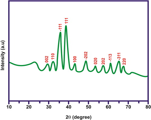
illustrates the X-ray diffraction patterns of the synthesised CuO/rGO nanocomposite and the prepared rGO and GO here. The positions of the diffraction peaks observed here for the composite samples accorded well with the standard CuO and rGO samples. The peaks (110), (-111), (111), (-202), (020), (202), (-113), (-311), (220) were consistent with the standard XRD pattern for the CuO monoclinic phase. Some extra peaks around (002) and (100) were observed which could be attributed to the reduced graphene oxide. Since GO was reduced successfully to RGO during the synthesis process, redox reaction took place and the characteristic peak of GO at (001) disappeared from the XRD pattern of the composite material. However, the intensity observed for the two characteristic reflection peaks of rGO in the composite material became much weaker than those of the as-prepared reduced graphene oxide. This happened due to the presence of less agglomerated, disordered stacking of the rGO sheets inside the composite matrix.
Figure 1. X-Ray diffraction patterns of CuO/rGO nanocomposite.
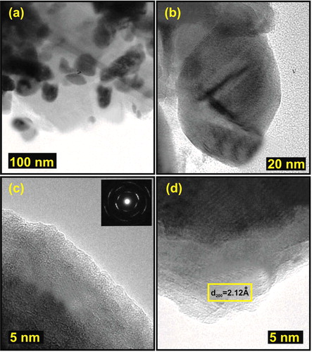
The TEM pictures of the synthesised sample are shown in . The TEM images gave the information regarding the size and morphology of the CuO/rGO as well as their agglomeration tendencies. From , it was observed that the pure CuO nanoparticles were agglomerated. The particle size obtained was in the range of 60–65 nm. The composite prepared here is highly crystalline in nature (). This type of interactions can ensure high mechanical flexibility of the reduced graphene nano-sheets and will prevent its’ agglomeration to large particles.
Figure 2. (a, b) TEM Images of CuO/rGO nanocomposite (c,d) HR TEM Images of CuO/rGO nanocomposite.
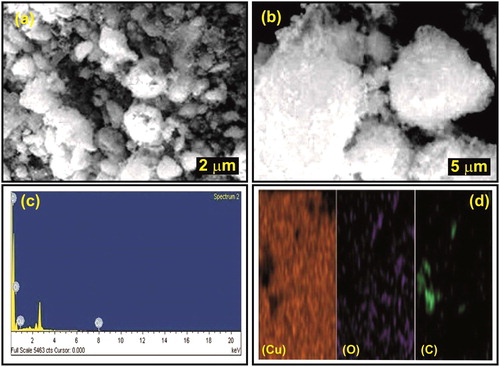
The SEM images of CuO nanoparticles are shown in . The spherical shape of the particles is clearly visible from the images. The surface texture was rough and uneven. However, the particle size determined was within the nano range. The SEM images confirmed the presence of stacked graphene sheets inside the composite matrix. The peaks observed from EDX spectrum showed the presence of all three elements (Cu, O and C) which confirmed the formation of CuO/rGO nanocomposite ().
Figure 3. SEM images and EDX spectrum of CuO/rGO Nanocomposite.
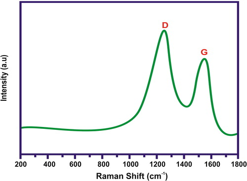
The FTIR spectrum of CuO/rGO nanocomposite is illustrated in . The vibration of the Cu–O bond was confirmed by the presence of the peak at 526 cm−1. This showed that the cuprous ions were oxidised to CuO by GO during the synthesis process. In addition, the OH stretching vibration occurred at 3433 cm−1. The results clearly demonstrated that the samples obtained here were partially reduced in presence of cuprous ions. shows the Raman spectrum of CuO/rGO composite. The D and G bands at 1330 and 1594 cm−1, respectively, were observed from the Raman spectrum of CuO/rGO composite. In general, it is accepted that the Raman ID/IG ratio (where ID and IG are the D- and G-peak Raman intensities, respectively) is related to the density of defects in graphene-based materials, and the graphitisation degree of carbonaceous materials.
Figure 4. FTIR spectrum of CuO/rGO nanocomposite.
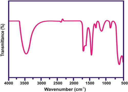
Figure 5. Raman spectrum of CuO/rGO nanocomposite.
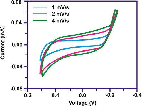
The cyclic voltammetry process was carried out to observe the electrochemical performance of the synthesised CuO/rGO nanocomposite for supercapacitor. This showed that the electrodes were consecutively charged and discharged over the whole voltammetric cycle. The capacitance behaviour of the nanocomposite was observed by the presence of anodic and cathodic peaks. This further confirmed that the surface redox reactions had been taken place. displays the CV profiles of the nanocomposite at different scan rates. A lower specific capacitance was observed using higher scan rate due to reduced charge storage capacity. This is expected for a higher scan rate as the electrolyte ions could not enter inside the interior part the electrode materials. The minimum area of the electrode was used by the electrolyte ions to years through at lower scan rate. This resulted in superior values for specific capacitance. Moreover, the electrochemical capacitive behaviour depends on the rate of charge exchange. This depends on the diffusion of anions and cations towards the electrode/electrolyte interfaces. CuO can diffuse on the surface of graphene and ensure more ions diffusion due to increase in interface zone between the electrode and electrolyte.
Figure 6. C–V characteristics of CuO/rGO-nanocomposite.
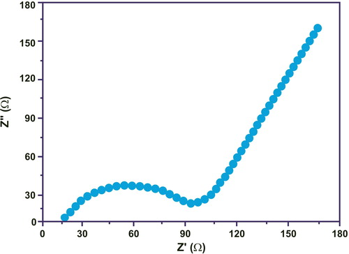
illustrated the EIS measurements on pure CuO nanoparticles. The behaviour of the electrodes was evaluated for three charge/discharge cycles. The intercept impedance on the Z-real axis reflects the electrolyte solution resistance, while the semicircle in the high middle frequency range and the oblique line at low frequencies represents the charge-transfer process and the lithium ion diffusion process (Warburg), respectively. Nyquist plots contain two parts – one is semicircle and another on is the straight line. At the high middle frequency region, the semicircle portion reflects the change transfer process around electrode/electrolyte interface. The straight line at lower frequency region illustrates the Warburg impedance process. The smaller diameter of the semicircle represents the reduced charge transfer resistance. Enhanced electron transfer with less resistance properties were observed using highly conductive reduced graphene nano-sheets. The polarisation rate was depressed due to reduced charge transfer resistance.
Figure 7. Nyquist plots of CuO/rGO nanocomposite.
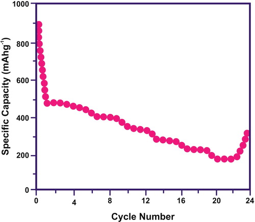
The specific capacitance values are inversely proportional with the scan rate. At a lower scan rate, positive ions (K+) can simply diffuse inside the every accessible site of materials. This initiates satisfactory insertion pathways for reaction. However, at higher scan rate, positive ions can approach only outer surface of the electrode. The constituent materials found inside the inward space has minor role to the capacitance behaviour. This initiates a slight deviation from ideality and less capacitance values. The highest reversible capacities with the best cycling stability were observed for the CuO/rGO nanocomposite electrode. Under various current densities, the specific capacity for the synthesised nanostructures was measured to improve the capacity of anodes and the results are plotted in . The nanoparticles of CuO were distributed homogenously over the rGO nanosheets. The particle aggregation was reduced by rGO nanosheets, thus electrochemical cycling problem was able to reduce the pulverisation of the electrode. It was noticed that rGO nano-sheets can conduct electricity. It can initial the internal resistance of the electrode-specific capacities. The ion transport path length was shortened due to CuO incorporation inside the rGO nano-sheets. Thus, electrode/electrolyte contact area was enhanced. The higher storage capacities with columbic efficiencies and cycling stabilities were observed. The electrochemical performance of the electrode was enhanced by the synergetic effect rGO nano-sheets and CuO nanoparticles. The nanocomposite electrode delivered a discharge capacity of the first cycle and maintained stable capacities from the second cycle with an excellent capacity retention.
Figure 8. The rate capabilities of the CuO/rGO nanocomposite.
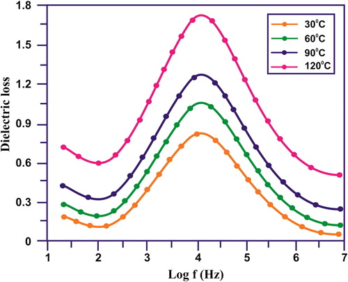
and illustrate the dielectric properties of the synthesised sample at different temperatures. A step-like decrease in dielectric constant with increasing frequency followed by Debye-like dipolar relaxations, i.e. dielectric loss peaks () of the CuO/rGO NC. At particular frequency range, the Debye-like dipolar relaxations was observed. This happened due to large dielectric response. Maxwell–Wagner–Sillars (MWS) interfacial polarisation effect was observed due to step like reduction in dielectric constant with different frequency levels [Citation26]. When the nanoparticles were under the interfaces of an electric field the space charge was accumulated at the interfaces of the electrode and nanoparticles, it was also present at the interfaces between the neighbouring grains at lower frequency level. The short range dipole interactions were observed at the interface between the neighbouring grains [Citation27]. This was attributed to the large interface to volume ratios. At lower frequency range, large MWS interfacial polarisation effect leads to range dielectric constant. At higher frequency level, the change carriers were confined, takes relatively Longley time was required for the accumulation and movement process. At various temperatures, the dielectric loss is illustrated as a function of frequency in . Both the values for dielectric loss and dielectric constant were reduced at an increased frequency level. The dielectric loss was professional with increasing temperatures. It is high at lower frequency level, but with enhanced temperatures it dropped significantly [Citation28, Citation29]. The magnitude of dielectric loss was increased with increasing temperature. This was evident and was further confirmed the thermally activated characteristics of the dielectric relaxation of the composite system [Citation30].
Figure 9. Dielectric constant of the CuO/rGO nanocomposite.
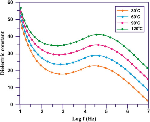
Figure 10. Dielectric loss of the CuO/rGO nanocomposite.
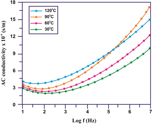
illustrates the behaviour of ac conductivities with frequency changes for the CuO/rGO nanocomposites. The conductivity of the CuO/rGO NC may be split into two regions: (i) the low-frequency region, where the conductivity is mostly influenced by dc conductivity and (ii) the high-frequency region, which is mainly distinguished by frequency-dependent conductivity which confirms the ac conductivity due to MWS interfacial polarisation effects and dielectric relaxations [Citation31]. Thus, due to MWS interfacial polarisation, the ac conductivities have increased with frequency for the CuO/rGO NC.
Figure 11. AC conductivity of the CuO/rGO nanocomposite.
4 Conclusion
A simple and cost-effective strategy has been developed to obtain CuO/rGO nanocomposites. Homogenous dispersion of CuO having monoclinic phase was observed over the surface of rGO. The XRD spectra confirmed the formation of CuO and rGO. Surface functional groups present over CuO and rGO were confirmed using FTIR and Raman analysis. Surface morphological features with particle size and shape were confirmed by FESEM and TEM analysis. The electrochemical performance of the CuO/rGO nanocomposite was enhanced due to the presence of graphene inside its matrix. The surface area of graphene sheets is greatly reduced by its aggregation intensities. This is attributed to its enhanced specific capacitance, better stability as well as increased wettability of the electrode materials. Hence, the electrochemical results suggest that CuO/rGO nanocomposite is a prominent candidate for high-performance supercapacitor devices. The dielectric constant, dielectric loss and AC conductivity were determined and the values were estimated at different frequencies and temperature level. The magnitude of dielectric constant and dielectric loss values were inversely proportional with increase in temperature and frequency. The conductivity behaviour revealed that the sample was here thermally activated. The AC conductivity values were dependent on the frequency level at higher temperature. At higher temperature, the values were increasing significantly. The AC conductivity was temperature dependent and with elevated temperature – it was increasing also.
Acknowledgements
This work has been made possible because of the generous grants RP044C-17AET and RP044D-17AET from the University Malaya, Malaysia. One of the authors (Suresh Sagadevan) acknowledges the honour, namely the “Visiting fellow” at the Department of Physics, Center for Defence Foundation Studies, Universiti Pertahanan Nasional Malaysia, Kem Sg. Besi, 57000 Kuala Lumpur, Malaysia. The author wishes to place on record his heartfelt thanks that are due to the authorities concerned.
References
- Geim AK, Novoselov KS. The rise of graphene. Nature Mater. 2007;6:183–191.
- He H, Klinowski J, Forster M, et al. A new structural model for graphite oxide. Chem. Phys. Lett. 1998;287:53.
- Stankovich S, Dikin DA, Kohlhaas KM, et al. Graphene-based composite materials. Nature. 2006;442:282–286.
- Qin J, Cao M, Li N, et al. Graphene-wrapped WO3 nanoparticles with improved performances in electrical conductivity and gas sensing properties. J Mater Chem. 2011;21:17167.
- Cheng Q, Tang J, Ma J, et al. Graphene and carbon nanotube composite electrodes for supercapacitors with ultra-high energy density. Phys Chem Chem Phys. 2011;13:17615.
- Yan XY, Tong L, Zhang YF, et al. Cuprous oxide nanoparticles dispersed on reduced graphene oxide as an efficient electrocatalyst for oxygen reduction reaction. Chem Commun (Camb). 2012;48:1892–1894.
- Salunkhe RR, Lee Y-H, Chang K-H, et al. Ultrahigh performance supercapacitors utilizing core–shell nanoarchitectures from a metal–organic framework-derived nanoporous carbon and a conducting polymer. Chem. Eur. J. 2014; 20:1–16.
- Salunkhe RR, Tang Kobayashi JN, et al. Ultrahigh performance supercapacitors utilizing core-shell nanoarchitectures from a metal-organic framework-derived nanoporous carbon and a conducting polymer. Chem Sci. 2016;7:5704–5713.
- Tang J, Yamauchi Y. Carbon materials: MOF morphologies in control. Nat Chem. 2016;8:638–639.
- Salunkhe RR, Kaneti YV, Yamauchi Y. Metal-organic framework-derived nanoporous metal oxides toward supercapacitor applications: progress and prospects. ACS Nano. 2017;11:5293–5308.
- Li B, Cao H, Yin G. Mg(OH)2@reduced graphene oxide composite for removal of dyes from water. J Mater Chem. 2011;21:13765.
- Li B, Cao H, Yin G, et al. Cu2O@reduced graphene oxide composite for removal of contaminants from water and supercapacitors. J. Mater. Chem. 2011; 21:10645.
- Willander M, Hasan K, Nur O, et al. Recent progress on growth and device development of ZnO and CuO nanostructures and graphene nanosheets. J. Mater. Chem. 2012; 22:2337.
- Jiang B, Tian C, Zhou W, et al. In situ growth of TiO2 in interlayers of expanded graphite for the Fabrication of TiO2-graphene with enhanced photocatalytic activity. Chem Eur J. 2011;17:8379.
- Chen H, Yu D, Wang S, et al. Oxidizing metal ions with graphene oxide: the in situ formation of magnetic nanoparticles on self-reduced graphene sheets for multifunctional applications. Chem Commun. 2011;47:11689.
- Scheuermann GM, Rumi L, Steurer P, et al. Palladium nanoparticles on graphite oxide and its functionalized graphene derivatives as highly active catalysts for the Suzuki-Miyaura coupling reaction. J Am Chem Soc. 2009;131:8262–8270.
- Guo S, Wen D, Zhai Y, et al. Platinum nanoparticle ensemble-on-graphene hybrid nanosheet: one-pot, rapid synthesis, and used as new electrode material for electrochemical sensing. ACS Nano. 2010;4:3959–3968.
- Muszynski R, Seger B, Kamat PV. Decorating graphene sheets with gold nanoparticles. J Phys Chem C. 2008;112:5263–5266.
- Manga KK, Wang S, Jaiswal M, et al. High-gain graphene-titanium oxide photoconductor made from inkjet printable ionic solution. Adv Mater Weinheim. 2010;22:5265–5270.
- Li B, Cao H, Shao J, et al. Superparamagnetic Fe3O4 nanocrystals@graphene composites for energy storage devices. J Mater Chem. 2011;21:5069–5075.
- Li B, Cao H. ZnO@graphene composite with enhanced performance for the removal of dye from water. J. Mater. Chem. 2011;21:3346–3349.
- Shaikh JS, Pawar RC, Moholkar AV, et al. CuO–PAA hybrid films: chemical synthesis and supercapacitor behavior. Appl Surf Sci. 2011;257:4389–4397.
- Zhang HX, Zhang ML. Synthesis of CuO nanocrystalline and their application as electrode materials for capacitors. Mater. Chem. Phys. 2008;108:184–187.
- Zhao B, Liu P, Zhuang H, et al. Hierarchical self-assembly of microscale leaf-like CuO on graphene sheets for high-performance electrochemical capacitors. J. Mater. Chem. A. 2013;1:367–373.
- Wang B, Wu XL, Shu CY, et al. Synthesis of CuO/graphene nanocomposite as a high-performance anode material for lithium-ion batteries. J Mater Chem. 2010;20:10661–10664.
- Sagadevan S, Pal K, Chowdhury ZZ, et al. Controllable synthesis of Graphene/ZnO-nanocomposite for novel switching. J Alloys Compd. 2017;728:645–654.
- Sagadevan S, Chowdhury ZZ, Hoque ME, et al. Chemically stabilized reduced graphene oxide/zirconia nanocomposite: synthesis and characterization. Mater Res Express. 2017;4:115031.
- Das I, Sagadevan S, Chowdhury ZZ, et al. A facile chemical route synthesis and characterization of CdSe/ZnO nanocomposite. J Mater Sci: Mater Electron. 29(2): 1600–1606. doi:10.1007/s10854-017-8070-4 (2017)
- Das I, Sagadevan S, Chowdhury ZZ, et al. Development, optimization and characterization of a two step sol–gel synthesis route for ZnO/SnO2 nanocomposite. J Mater Sci: Mater Electron. 2017;29(5):4128–4135. doi:10.1007/s10854-017-8357-5.
- Sagadevan S, Pal K, Chowdhury ZZ. Scalable synthesis of CdS–Graphene nanocomposite spectroscopic characterizations. J Mater Sci: Mater Electron. 2017;28:17193–17201.
- Sagadevan S, Pal K, Koteeswari P, et al. Synthesis and characterization of TiO2/graphene oxide nanocomposite. J Mater Sci: Mater Electron. 2017;28:7892–7898.