
Abstract
The study focuses on the fabrication and properties evaluation of dual functional electrospun polycaprolactone scaffolds incorporating antibiotic drug cefuroxime and having custom tailored topography for the support of human cells to be used in tissue regeneration. The scaffolds were evaluated in regard to their morphology, total porosity, thermal properties, tensile properties and cells adhesion/growth, thus to define the effect of both drug content and physical architecture on the scaffolds properties. Both the addition of the drug and the scaffolds custom topography resulted in higher total porosity (up to 90%), while the fibers diameter highest reduction was up to 73%. The type of 3 D printed collector influenced scaffolds tensile properties, thus the increase of the tensile strength was due to the change of the central cylinder height in the hexagonal geometry of the collectors. Cells distribution and spreading on the electrospun scaffolds after 72 hours, showed that scaffolds with custom topography have more evenly scattered cells than the ones with random electrospun fibers. The study has demonstrated that both drug concentration and scaffolds target topography influenced the scaffolds properties and both can be optimized depending on scaffolds demands.
1. Introduction
One of the application areas of electrospun nanofibrous materials is biomedicine, i.e. tissue engineering where these materials can be used as scaffolds for tissue cells culture. Taking into account that nanofibers can be found in nature as basic building blocks, i.e. collagen, these man made nanofibrous materials are perfect candidates for the development of hierarchically organized nanocomposites (scaffolds) [Citation1,Citation2] that will mimic the structure of human tissues for the purpose of tissue regeneration or potentially total organ replacement. Advantageous properties of nanofibrous materials include high and tuneable porosity, structural integrity, light weight, high surface-to-volume ratio, adjustable fiber diameter/morphology, sizes and shapes, and well-controlled functionality [Citation3,Citation4]. In the biomedical field these materials can provide both cells growth support [Citation5,Citation6] but also controlled drug release [Citation7,Citation8] where necessary. Many studies suggest that electrospun nanofibers are also good medicine carriers and depending on their configuration the pace of release can be: immediate or fast [Citation9], postponed or slow [Citation10] and biphasic where a combination of both immediate and sustained release profiles are present [Citation11]. The pace drug release depends on the type of polymer, usually biodegradable polymers are used with different periods of biodegradability. The pace release also depends on the fibers configurations thus fibers can be produced by blend electrospinning [Citation12], emulsion electrospinning [Citation13] or bi-component electrospinning [Citation14], where homogeneous blend polymers/drugs fibers, dispersed drugs in polymers matrices fibers or fibers with core (drugs)/shell (polymers) cross-sections can be made, respectively. Multiaxial electrospinning is also reported and it may provide the incorporation of more than one drug component, but also contributes in the controlled release function [Citation15]. Some drugs can be incorporated by post processing surface modifications or even through electrospraying. When nanofibers have target functionalization, drugs can be released by outside stimulations including: pH, temperature, light, electric field, magnetic field or combination of all mentioned parameters [Citation16,Citation17]. Apart from the basic fiber configuration design the drug pace release can be altered through the incorporation of nanoparticles or nanotubes. In this way a prolonged drug release can be obtained which is important against post-surgery inflammations. Authors have reported an improved work, over their previous study [Citation18], where metronidazole-loaded halloysite clay nanotubes acting as drug containers were encapsulated into electrospun poly(caprolactone)/gelatin fibers. The nanotubes have extended the drug release over 20 days and provided protection against Fusobacteria, while when directly introduced into the polymer solution the release was up to 4 days only [Citation19].
Type of medical components incorporated into the electrospun scaffolds may include various antibiotics, antibacterial agents, antitumor drugs and biologically active components such as: protein, DNA, RNA and cells growth factors [Citation20]. Combined processes including diffusion, polymer degradation, drug dissolution and partitioning, are drug release mechanisms in electrospun scaffolds. Drug diffusion rate depends on the polymer hydrophilicity, drug diffusivity, solubility and partitioning. The drug diffusion distance in biodegradable polymers changes with the rate of degradation while for non-biodegradable polymers depends on its fixed form [Citation21].
To modulate the drug release profile emulsion electrospun fibers can be perfect candidates i.e. study reports on emulsion electrospinning of metformin hydrochloride or metoprolol tartrate with poly(ε-caprolactone) (PCL) or poly(3-hydroxybutyric acid-co-3-hydroxyvaleric acid) (PHBV). This type of fibers configuration reduced the burst release thus resulted in sustained drugs release [Citation22]. The type of polymer content has affected the drug release profile as reported in a study of core (polycaprolactone-PCL)/shell (PCL/polilactic acid-PLA blend) electrospun fibers, where tetracycline hydrochloride wound healing antibiotic was incorporated in the PCL core of the fibers. A tunable burst release profile was designed due to the shell diffusion barrier property. At higher PLA shell contents there was less diffusion of the drug, while the pure PCL shell results in free, almost total drug release [Citation23]. Some of the studies reported, concerning stimuli-responsive drug release, described the incorporation of the drug doxorubicin into electrospun thermos-responsive poly(NIPAAm-co-HMAAm) fibers additionally encapsulating magnetic nanoparticles. External alternating magnetic field affecting the nanoparticles resulted in heat generation thus temperature change which caused drug release due to polymer swelling. When the magnetic field was removed, the polymer has shrunk thus the drug release was ended. This type of switchable controlled drug release is to be used in anticancer (melanoma) treatment, thus 70% of the cancer cells were killed in 5 minutes due to both drug effect and heat [Citation24]. Some studies reported on a dual drug incorporation and delivery trough electrospun polymer blends, where the release of the individual drugs is controlled according to the patient’s therapy regimen. Aceclofenac and pantoprazole were incorporated into solutions of zein and eudragit S 100, respectively, while the polymer solutions were electrospun as blended in a one-step procedure. The simultaneous activity of the proton pump inhibitors and non-steroidal anti-inflammatory drugs were used to prevent gastrointestinal toxicity in patients using non-steroidal anti-inflammatory drugs and to enhance the rate of ulcer healing [Citation25].
Another aspect in the development of electrospun scaffolds is their intrinsic 2 D architecture that still challenges the research in this field. This is a problem in regard to cells in-depth penetration after seeding. Some of the ways that researchers have described in order to overcome this challenge and to control the fibrous structure thus to produce 3 D architectures include: dual extrusion electrospinning, temperature assisted electrospinning, micro-patterned collector electrospinning, post processing electrospinning, electrospinning with a coagulation bath, electrospinning with gas foaming or self-assembly, fibrous yarn production, electrospinning with hydro gel formation and near-field electrospinning [Citation26].
In this study polycaprolactone scaffolds with custom tailored topography were produced combining electrospinning with 3 D printed collectors. The scaffolds were characterized by their dual drug and cells support function. A model of non-toxic drug used was cefuroxime that is known for its activity against both gram-positive and gram-negative bacteria in the protection of soft tissue infections [Citation27]. The scaffolds were fabricated with two drug concentrations and four different topographies, while evaluated in regard to their morphology, total porosity, thermal properties, tensile properties and cells adhesion/growth. To best of knowledge studies considering the topographical aspect of electrospun scaffolds have not evaluated differences in the geometrical parameters of collectors influencing the scaffolds structures thus scaffolds properties. Usually collectors with special geometries were observed in one single form only. In this study, the main focus is on the forth-mentioned issue. Thus, the change of the central cylinder height in the hexagonal geometry of the 3 D printed collectors has shown its effect on the fibers morphology, scaffolds porosity and tensile strength, all of paramount importance in the development of tissue scaffolds in respect to cells adhesion and mechanical integrity needed to overcome the stresses during tissue growth.
2. Experimental part
Materials used in this work were: polycaprolactone (PCL) with Mn = 80,000 (Sigma Aldrich) and antibiotic cefuroxime (CFU) (Astro Pharm). Polymer solution of 18% was prepared by dissolving the polymer in glacial acetic acid and acetone with the volume ratio of 8:2. The concentration of the antibiotic was 5 and 10 wt% in regard to the polymer mass. The blend solution was prepared by dissolving the polymer with the addition of the antibiotic with constant stirring and heating at 50 °C.
As prepared solutions were electrospun on electrospinning device, NT-ESS-300, NTSEE Co. Ltd. South Korea. The processing conditions were: electrical voltage of 15-17 kV, needle tip to collector distance of 18 cm and volume flow rate of 1 ml/h. The fibrous scaffolds were collected on 3 D printed collectors with target geometry. The collectors were prepared on Form 2 3 D printer FormLabs, by using a photoreactive resin that is a mixture of methacrylic acid esters and a photoinitiator, as the raw material. The geometry of the collectors was designed in compliance with the requirements of eye tissue regeneration. The basic geometrical element was hexagon, or a honeycomb polygon where the height of the central cylinder was varied, . The dimensions of the basic elements, in the hexagonal geometry of the 3 D printed collectors are given in .
Figure 1. Geometry of the 3 D printed collectors (Catia V5, measurements given in mm) and PCL/CF electrospun scaffolds on the 3 D printed collectors.
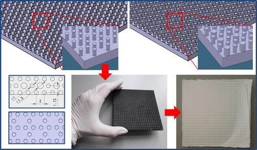
Table 1. Dimensions of the basic elements, in the hexagonal geometry of the 3 D printed collectors.
The electrospun scaffolds were evaluated in regard to their morphology, total porosity, tensile properties, thermal properties and surface cells adhesion/growth.
For the morphology analysis the PCL and PCL/CFU samples were imaged under scanning electron microscopy, SEM FEG Quanta 250 FEI with previous Au/Pd coating of 15 seconds. The morphology (fibers diameter and pores area) was determined based on the SEM images by measuring randomly selected fibers and pores respectively, using the ImageJ-NIH software. The total porosity of the materials was calculated using the equation reported elsewhere [Citation28]. Materials thickness was measured using a Digi Micrometer, Mitutoyo, no. 393-340-30.
The tensile properties of the electrospun scaffolds were tested with Dinamometar Tensolab 3000 - tt. Mesdan S.p.A., Italy. The load cell was 100 N with a rate of extension of 20 mm/min. The samples were cut into 0.5 x 10 cm and were tested each five times using gauge length of 20 mm.
The thermal properties were determined with differential scanning calorimetry Mettler Toledo DSC 822e by placing 9 mg of the samples into aluminium pans. The samples were heated from 25 °C to 80 °C and held for 5 minutes at the final temperature to erase any thermal history. The cooling was till −100 °C with the rate of 10 °C/min. The characteristic temperatures and heat of fusion and crystallization were obtained from the DSC curves peaks and area below the peaks.
For PCL/CFU scaffolds biocompatibility testing HeLa cell line was used. It is an epithelial cell line with very good adhesion properties standardly used in many material biocompatibility studies. The cell inoculum for scaffold seeding was produced in a Petri dish with DMEM culture medium and 10% fetal bovine serum, incubated at 37 °C in humidified CO2 incubator. Prior to cell seeding, the electrospun scaffold sheets were cut into circular shaped discs that were embedded in wells of 24-well plate. The discs were there cleaned and sterilized by soaking in 70% ethanol and exposing to UV light under laminar-flow hood for 60 min. The ethanol was removed from the plate and discs were washed twice in culture medium with serum. The cell inoculum was harvested form Petri dish using 0.25% trypsin (Sigma) and set to concentration of 200.000 cells/ml. Into each well 0.5 ml of cell inoculum was added. The plate was left static inside the incubator for cells to attach. After 6 hours the culture medium was replaced with the fresh one. The plate was incubated for the next 72 hours. After 24 and 72 hours post seeding three discs with and w/o custom topography were taken out and underwent standard 3-(4,5-dimethylthiazol-2-yl)-2,5-diphenyltetrazolium bromide (MTT) assay. The discs were subsequently visually inspected for development of purple colour. The control discs were not seeded with cells, but also incubated in culture media and MTT assay treated. The seeding efficiency is expressed as percentage derived from the ratio of spectrophotometric absorbance values of the cells attached on scaffold disc surface and the cells attached on empty well surface (of 24-well plate). The MTT assay six hours after cell seeding was performed in order to obtain the absorbance values at the wave length of 570 nm.
3. Results and discussion
3.1. PCL/CFU fibers morphology and materials total porosity
The starting point in electrospun scaffolds development concerns the fibers and pores sizes as well as morphology, which affect scaffolds total porosity. A dual structure comprising both nanofibers and micro pores would give the ideal scaffold for cells adhesion and in-depth penetration. Generally in electrospinning nanofibers form small sized pores when electrospun on a flat collector plates due to their dense positioning. A loosen structure coming from a target topography would be more favourable for both cells adhesion and further colonization. Such a structure was the focus of this study. gives the SEM images of the electrospun PCL/CFU scaffolds. Firstly, the controlled positioning of the fibers is rather visible on (right down corner) with the custom tailored topography representing the geometry of the 3 D hexagonal printed collectors. The controlled deposition of the fibers during electrospinning has provided the formation of the hexagonal pockets which are favourable for the accommodation of the tissue cells. Depending on the time of electrospinning this topography can be compromised, thus after long time of electrospinning the structure can be lost. For this reason an optimal time of electrospinning is necessary. In regard to fibers morphology, generally the fibers have shown homogeneity with random beads formation in case of the scaffolds with higher CFU concentration (). The lower the height of the central cylinder was (or in case of collector no. 1), the more elongated beads were present in the fibrous structure (). The addition of the 5 wt% CFU resulted in no beads formation, but rather random inhomogeneous thickenings along some fibers lengths ( and ). presents the fibers diameter and pores area distributions, while in the fibers mean diameters, mean pores area and the scaffolds total calculated porosity are given. Generally the addition of the medicine to the PCL, as well as the increase of its wt% concentration, resulted in fibers diameter reduction up to 73%. In electrospinning this result is suggested due to two reasons: increase of the charge carriers (drug chemical composition) in the solution or interruption of the chain entanglements (drug small molecule), resulting in higher stretching force for longer period of the jet flight and reduced viscosity, respectively [Citation29–31]. Apart from the drug influence, the changes of the collector geometry have also affected the fibers final diameter. Generally the addition of the central cylinder in the “hexagon” geometry and the increase of its height resulted in fibers diameter reduction. The reason for this result is due to the height difference between the smaller and the central big cylinder, thus the fibers attracted by both, stretch more to deposit on the conductive surfaces. In this way a 3 D structure is formed due to the controlled deposition of the fibers.
Figure 2. SEM images of the electrospun scaffolds: a) neat PCL, b) PCL/5% CFU1, c) PCL/10% CFU1, d) PCL/5% CFU2, e) PCL/10% CFU2, f) PCL/5% CFU3, g) PCL/10% CFU3, h) PCL/5% CFU4, i) PCL/10% CFU4.
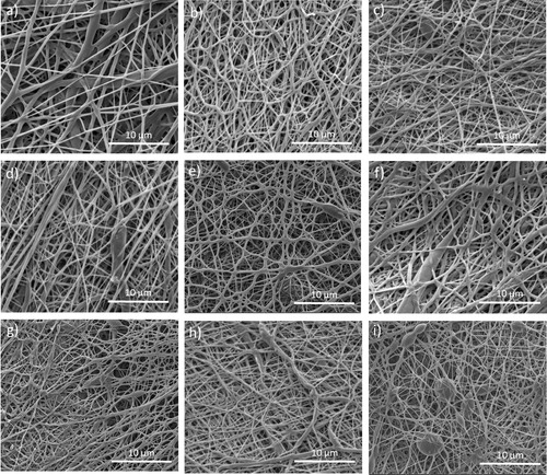
Figure 3. Fibers diameters (a) and pores area (b) distribution of the electrospun PCL/CFU scaffolds.
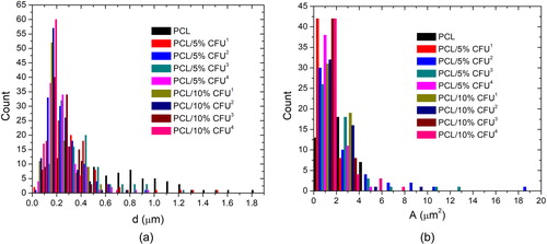
Table 2. Fibers diameter, pores area and electrospun materials total porosity.
Generally the higher the difference between the cylinders the higher the reduction of the fibers diameters was present, i.e. collector 1 (no central cylinder) the electrospun PCL/5% CFU1 showed fibers diameter of 371 nm, while the same composition on collector 4 was electrospun into a mean fibers of 256 nm.
In case of the electrospun PCL/10% CFU the change of the collector from 1 to 4 resulted in fibers diameter reduction from 221 nm do 168 nm. The exception was in case of the collector 3, where the opposite effect was noticed. This might be due to a possible nonhomogeneous CFU distribution along the fibers. Generally the addition of the drug as well as the change of the collectors, have also reduced the pores area, although this change was not as significant. The biggest difference was in case of collector 2 with the change from 3.033 to 1.740 µm2. Finally it can be concluded that the geometry of the collector is as influential as the fiber composition in the design of the final 3 D scaffolds structure. In regards to scaffolds total porosity, , generally the calculated values revealed that both the addition of the drug and the scaffolds custom topography resulted in higher total porosity or above 71%.
This is the result of the fibers diameter decrease but also the increase of the distance between the smaller and the central cylinder in the hexagonal geometry as it is noticed that the higher drug concentration added and the highest distance between the smaller and the central cylinder resulted in higher total porosity. The highest total porosity calculated was in case of the PCL/10% CFU4 scaffolds of almost 90%.
3.2. PCL/CFU scaffolds thermal behaviour
To understand how the drug and its content influenced the thermal behaviour or thermal degradation of the scaffolds matrix, i.e. the PCL, the materials were subjected to heating and cooling or heating only over a temperature range. The chemical composition of the two components or their miscibility strongly affects the thermal behaviour and thermal degradation of the scaffolds.
and , gives the DSC curves of the electrospun scaffolds during heating and cooling from −100 to 100 °C. This result can confirm the presence of the CFU after dissolution in the organic solvents as well as its effect on the thermal behaviour of the polymer. gives the peak melting and crystallization temperatures, the glass transition temperatures and the heat of melting and crystallization. The endothermic peak of the neat electrospun PCL was at around 55 °C and it was almost the same for the scaffolds with the added drug as well, which confirms the polymer crystalline structure [Citation32].
Figure 4. DSC curves of the electrospun PCL/CFU scaffolds during heating (a) and cooling (b).
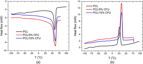
Table 3. Peak temperature of melting and crystallization, glass transition temperature and heat of melting and crystallization.
The glass transition temperature of the neat PCL was around −60 °C, while for the drug loaded samples it was slightly reduced showing the plasticizing effect of the drug to the polymer. The added drug had no significant effect on the polymer melting point. The nucleating effect of the drug CFU was observed due to the increase in the PCL crystallization temperature from 26 to almost ∼34 °C, suggesting that the crystallization was faster. In this regard it was noted that the difference in the crystallization temperature was insignificant between the 5 and 10 wt% of the CFU. This may suggest that nonhomogeneous drug distribution was present which then slows the crystallization process. In regard to the heat of fusion and crystallization it is seen that the addition and increase of the drug content reduces both, which suggests the total effect of the drug on the electrospun polymer thermal behaviour [Citation33].
3.3. PCL/CFU scaffolds thermal degradation
and present the TGA and DTG curves of the electrospun scaffolds showing the effect of the added drug on the PCL thermal stability and the maximum rates of its thermal degradation with the increase of the temperature. The characteristic temperatures are given in , including the initial and final degradation temperature, the temperature of the maximum rate of degradation and the residue at 600 °C. Firstly, the addition of the cefuroxime resulted in the two step degradation process as the degradation of the drug in the polymer started near 200 °C. As the initial temperature of the electrospun PCL increased from 366.50 to 377.58 °C for the 5 wt% of the CFU added, it is suggested that in this case the thermal stability of the scaffold was increased. In case of the 10 wt% of the CFU added the opposite effect was obtained. The same was noticed for the final and the maximum temperatures. The increase in the decomposition temperature of the PCL/5% CFU scaffolds may be due to their good physical mixing [Citation34].
Figure 5. TGA (a) and DTG (b) curves of the electrospun PCL/CFU scaffolds.
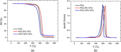
Table 4. Initial, final and maximum temperature and residue during degradation.
The DTG curves define the temperatures of the maximum rate of degradation of the electrospun scaffolds. The addition of the 5 wt% of the CFU resulted in the increase in this temperature from 407.90 °C to 431.79 °C, while in case of the 10 wt% CFU the temperature shifted to lower value of 397.41 °C. The results suggest both slower and faster degradation rate change, respectively. This again suggests possible agglomerations of the drug or nonhomogeneous distribution in the PCL fibers. The small peaks at 238.29 and 221.16 °C for the electrospun PCL/5% CFU and PCL/10% CFU, respectively present the maximum degradation rate for the antibiotic itself. The increase of the antibiotic content also increased the residue of the scaffolds after degradation compared to the neat PCL which suggests its presence in the composite scaffolds.
3.4. PCL/CFU scaffolds tensile properties
One of the most important properties of tissue engineering scaffolds is their mechanical integrity, thus the scaffold needs to meet the requirements for mechanically stable structure to support cells attachment, migration as well as free delivery and diffusion of nutrients important for their vitality. Within this respect the tensile properties of the scaffolds were evaluated concerning drug content as well as collector geometry variation. Both parameters affected the scaffolds tensile strength needed to withstand tissue forces during their growth or total regeneration. presents the behaviour of the electrospun PCL and PCL/CFU scaffolds with 5 and 10 wt% of the drug added, respectively, during tensile testing, thus the increase of the applied load and the strain obtained. gives the values of the maximum load, maximum strain and the tensile strength of the scaffolds.
Figure 6. Tensile test behavior of the electrospun PCL/CFU scaffolds with 5 wt% (a) and 10 wt% (b) of the drug added.
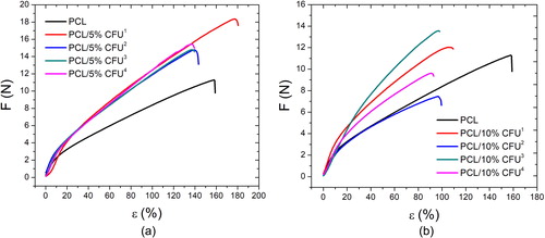
Table 5. Maximum force, elongation and tensile strength of the electrospun scaffolds.
Generally the addition of the 5 wt% drug has resulted in the increase of the maximum force and the tensile strength while the effect on the strain was opposite. This suggests that the type of 3 D printed collector influenced the results obtained, thus the increase of the tensile strength is due to the change of the height of the central cylinder in the hexagonal geometry of the collector. The highest tensile strength calculated was 15.17 MPa for the PCL/5% CFU2 scaffold. In case of the 10 wt% of the added CFU both increase and decrease of the maximum force and tensile strength was noticed. The highest tensile strength of 21.27 MPa was obtained for the PCL/10% CF3 scaffold. In case of the strain change, the addition and increase of the CFU content resulted in decrease of the strain for all types of collectors, with the max decrease of up to 70% in case of the PCL/10% CFU4. The variation of the trend in case of the scaffolds with the 10 wt% CFU can suggest that the higher the amount of the drug, the higher the possibility of inhomogeneous drug distribution in the polymer, thus the values of the mechanical properties may vary as well. Some studies reported on the influence of the fibers diameter on the scaffolds tensile properties thus the tensile strength. It was reported that the smaller the fibers mean diameter the higher the scaffolds tensile strength, which in this study agrees with the results in case of the scaffolds electrospun on collectors 1 and 3 [Citation35,Citation36].
3.5. PCL/CFU scaffolds cells adhesion
In this study the as developed PCL/CFU scaffolds were evaluated in regard to cells seeding and adhesion only. For this purpose HeLa human cell line was used as the model cells which are known for their high growth rate. The efficiency of HeLa cells adhesion comparatively tested using MTT assay on two types of electrospun PCL/10% CFU scaffolds (with random fibers and fibrous custom topography) did not show significant difference, . The bar chart in shows the efficiency of cell adherence on the surface of produced electrospun scaffolds six hours post seeding. In the experiment, empty wells of the cultivation plate (i.e. the wells without implanted scaffold) served as the control seeding area to be used for converting values of cell colorimetric quantification to percentage. The MTT assay was carried out in triplicates and showed no significant difference in attachment success of 100.000 cells seeded per tested scaffold (disc).
Figure 7. HeLa cell seeding efficiency on two different electrospun scaffold types, six hours after seeding.
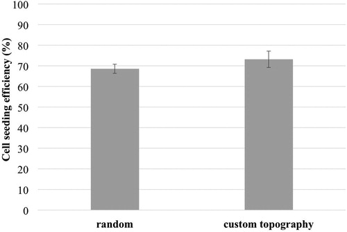
Both scaffold types were about 30% less favourable for cell attachment than the surface of commercial multi-well plate that served as control. This could be also due to the imperfection of the chosen seeding method, considering the fact that certain amount of cells always ended up under the scaffold discs during the seeding procedure. Some sort of disc immobilization inside wells, without compromising sterility, could thus improve the precision of the cell seeding method. Furthermore visual assessment of cell distribution and spreading on discs over 72 hours, using MTT cell staining, , showed that discs with custom topography have more evenly scattered cells than the discs with random electrospun fibres.
Figure 8. MTT staining of HeLa cells growing on two types of electrospun scaffolds 24 and 72 hours after cell seeding.
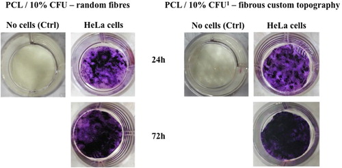
In this context, shows how the HeLa cells (dark purple colour) begin to situate mostly in the “pockets” of the scaffolds surface, or on the fibrous structure formed in the space (lighter colour) between the cylinders in the 3 D printed hexagonal geometry.
Figure 9. HeLa cells adhesion on the electrospun scaffolds with custom topography under optical microscopy.
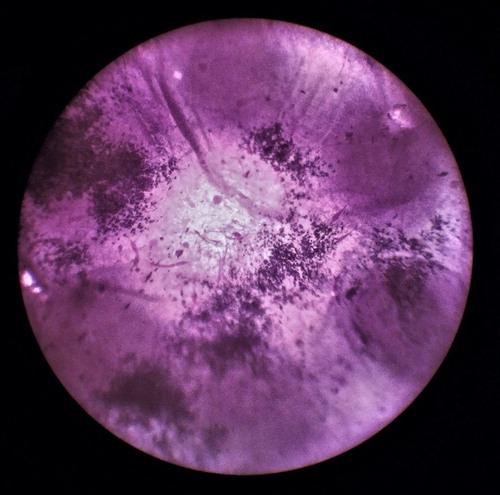
This is the space of the scaffolds where fibers are forming loosen structure which is more favourable to the micron cells, unlike the flat surface or the top of the cylinders where the fibers are tightly packed during electrospinning. This leads to the conclusion that appropriate topographic pattern on cell colonized disc could require less time for reaching full cell confluence, which is indicated by our experiment.
4. Conclusions
The study reports on the development of electrospun PCL/CFU scaffolds with dual drug and cells support function. The scaffolds had target topography as a result of controlled deposition of the fibers onto 3 D printed collectors with defined hexagonal geometry. The scaffolds were evaluated in regard to their morphology, total porosity, thermal properties, tensile properties and cells adhesion/growth, thus to define the effect of both drug content and physical architecture on the scaffolds properties.
The addition of the drug to the PCL, as well as the increase of its wt% concentration, resulted in fibers diameter reduction up to 73%. Random beads formation was present in case of the scaffolds with higher CFU concentration. The addition of the drug as well as the change of the collectors, reduced the pores area, but this change was not as significant. The calculated total porosity revealed that both the addition of the drug and the scaffolds custom topography resulted mostly in higher total porosity or above 71%. The highest total porosity calculated was in case of the PCL/10% CFU4 scaffolds of almost 90%. The added drug had no significant effect on the polymer melting point, but nucleating effect of the drug CFU was observed due to the increase in the PCL crystallization temperature from 26 to almost ∼34 °C, suggesting that the crystallization was faster. The good physical mixing between the drug and the polymer resulted in the increase of the decomposition temperature of the PCL/5% CFU scaffolds. The addition of the 5 wt% CFU has resulted in the increase of the maximum force and the tensile strength while the effect on the strain was opposite. The type of 3 D printed collector influenced the results obtained, thus the increase of the tensile strength is due to the change of the height of the central cylinder in the hexagonal geometry of the collector. The variation of the trend in case of the scaffolds with the 10 wt% CFU suggested that the higher the amount of the drug, the higher the possibility of inhomogeneous drug distribution in the polymer. HeLa cells distribution and spreading on the electrospun scaffolds after 72 hours, showed that scaffolds with custom topography have more evenly scattered cells than the ones with random electrospun fibres. This leads to the conclusion that appropriate topographic pattern created on scaffolds may shorten time needed for reaching full cells confluence. Finally, the study has demonstrated that both drug concentration and scaffolds target topography influenced the scaffolds properties and both can be optimized depending on scaffolds demands.
Acknowledgement
This work has been fully supported by Croatian Science Foundation under the project IP-2016-06-6878, Custom Tailored Fibrous Scaffold Prototype for Tissue Cells Culture via Combined Electrospinning, COMBOELECTROSPUN.
Disclosure statement
The authors declare that there are no conflicts of interests concerning this work.
Additional information
Funding
References
- Teo W-E, Ramakrishna S. Electrospun nanofibers as a platform for multifunctional, hierarchically organized nanocomposite. Compos Sci Technol. 2009;69:1804–1817.
- Xu T, Miszuk JM, Zhao Y, et al. Electrospun Polycaprolactone 3D Nanofibrous Scaffold with Interconnected and Hierarchically Structured Pores for Bone Tissue Engineering. Adv Healthc Mater. 2015;4:2238–2246.
- Liu H, Ding X, Zhou G, et al. Electrospinning of nanofibers for tissue engineering applications. J Nanomater. 2013;2013:11.
- Zdraveva E, Fang J, Mijovic B, et al. Structure and Properties of High-Performance Fibers: Oxford, Woodhead Publishing. 2017, Chapter 11, Electrospun nanofibers, p. 267–300.
- Mijovic B, Trcin MT, Agic A, et al. Study on cell adhesion detection onto biodegradable electrospun PCL scaffolds. JFBI. 2012;5:33–40.
- Jiang Y-C, Jiang L, Huang A, et al. Electrospun polycaprolactone/gelatin composites with enhanced cell–matrix interactions as blood vessel endothelial layer scaffolds. Mater Sci Eng C. 2017;71:901–908.
- Nagy ZK, Nyúl K, Wagner I, et al. Electrospun water soluble polymer mat for ultrafast release of Donepezil HCl. Express Polym Lett. 2010;4:763–772.
- Paaver U, Heinämäki J, Laidmäe I, et al. Electrospun nanofibers as a potential controlled-release solid dispersion system for poorly water-soluble drugs. Int J Pharm. 2015;479:252–260.
- Li X, Kanjwal MA, Lin L, et al. Electrospun polyvinyl-alcohol nanofibers as oral fast-dissolving delivery system of caffeine and riboflavin. Colloids Surf B Biointerfaces. 2013;103:182–188.
- Bonthagarala B, Swain S, Rao PV, et al. Design and Characterization of Controlled Release Lornoxicam Nanofibers by Electrospinning Technique. Int J of Biomed & Adv Res. 2015;6:220–232.
- Yu D, Wang X, Li X, et al. Electrospun biphasic drug release polyvinylpyrrolidone/ethyl cellulose core/sheath nanofibers. Acta Biomater. 2013;9:5665–5672.
- Blakney AK, Krogstad EA, Jiang YH, et al. Delivery of multipurpose prevention drug combinations from electrospun nanofibers using composite microarchitectures. Int J Nanomedicine. 2014;9:2967–2978.
- Hu J, Wei J, Liu W, et al. Preparation and characterization of electrospun PLGA/gelatin nanofibers as a drug delivery system by emulsion electrospinning. J Biomater Sci Polym Ed. 2013;24:972–985.
- Llorens E, Ibañez H, Del Valle L, et al. Biocompatibility and drug release behavior of scaffolds prepared by coaxial electrospinning of poly (butylene succinate) and polyethylene glycol. Mater Sci Eng C. 2015;49:472–484.
- Han D, Steckl AJ. Triaxial electrospun nanofiber membranes for controlled dual release of functional molecules. ACS Appl Mater Interfaces. 2013;5:8241–8245.
- Manuel CBJ, Jesús VGL, Aracely SM. Electrospinning for Drug Delivery Systems: Drug Incorporation Techniques. In: Electrospinning-Material, Techniques, and Biomedical Applications: InTech. 2016. p. 141–155.
- Weng L, Xie J. Smart electrospun nanofibers for controlled drug release: recent advances and new perspectives. Curr Pharm Des. 2015;21:1944–1959.
- Xue J, He M, Liu H, et al. Drug loaded homogeneous electrospun PCL/gelatin hybrid nanofiber structures for anti-infective tissue regeneration membranes. Biomaterials. 2014;35:9395–9405.
- Xue J, Niu Y, Gong M, et al. Electrospun microfiber membranes embedded with drug-loaded clay nanotubes for sustained antimicrobial protection. ACS Nano. 2015;9:1600–1612.
- Hu X, Liu S, Zhou G, et al. Electrospinning of polymeric nanofibers for drug delivery applications. J Control Release. 2014;185:12–21.
- Chou S-F, Carson D, Woodrow KA. Current strategies for sustaining drug release from electrospun nanofibers. J Control Release. 2015;220:584–591.
- Hu J, Prabhakaran MP, Tian L, et al. Drug-loaded emulsion electrospun nanofibers: characterization, drug release and in vitro biocompatibility. RSC Adv. 2015;5:100256–100267.
- Pedersbæk D, Frantzen MT, Fojan P. Electrospinning of Core-Shell Fibers for Drug Release Systems. JSAME. 2017;5:17–30.
- Kim YJ, Ebara M, Aoyagi T. A smart hyperthermia nanofiber with switchable drug release for inducing cancer apoptosis. Adv Funct Mater. 2013;23:5753–5761.
- Karthikeyan K, Guhathakarta S, Rajaram R, et al. Electrospun zein/eudragit nanofibers based dual drug delivery system for the simultaneous delivery of aceclofenac and pantoprazole. Int J Pharm. 2012;438:117–122.
- Jun I, Han H-S, Edwards J, et al. Electrospun fibrous scaffolds for tissue engineering: viewpoints on architecture and fabrication. Int J Mol Sci. 2018;19:745.
- Hugo H, Dornbusch K, Sterner G. Cefuroxime in soft tissue infections and septicaemia. Scand J Infect Dis. 1980;12:227–230.
- Zdraveva E, Mijović B, Bajsić EG, et al. Morphological characteristics of nanofibrous materials in dependence of the filler concentration. In: Hodžić A, Omer SE, Hodžić D, editors. Proceedings of the 11th International Scientific Conference on Production Engineering; 2017 October 4-7; Sarajevo, B&H: Univerzitet u Bihaću, Tehnički fakultet; 2017. p. 543–548
- Johnson CD, D'amato AR, Gilbert RJ. Electrospun fibers for drug delivery after spinal cord injury and the effects of drug incorporation on fiber properties. Cells Tissues Organs. 2016;202:116–135.
- Zamani M, Morshed M, Varshosaz J, et al. Controlled release of metronidazole benzoate from poly ε-caprolactone electrospun nanofibers for periodontal diseases. Eur J Pharm Biopharm. 2010;75:179–185.
- Zong X, Kim K, Fang D, et al. Structure and process relationship of electrospun bioabsorbable nanofiber membranes. Polymer. 2002;43:4403–4412.
- Rychter M, Baranowska-Korczyc A, Milanowski B, et al. Cilostazol-Loaded Poly (ε-Caprolactone) Electrospun Drug Delivery System for Cardiovascular Applications. Pharm Res. 2018;35:32.
- Cerkez I, Sezer A, Bhullar SK. Fabrication and characterization of electrospun poly (e-caprolactone) fibrous membrane with antibacterial functionality. R Soc Open Sci. 2017;4:160911.
- Prabu P, Kim KW, Dharmaraj N, et al. Antimicrobial drug release scaffolds of natural and synthetic biodegradable polymers. Macromol Res. 2008;16:303–307.
- Hassan MI, Sultana N. Characterization, drug loading and antibacterial activity of nanohydroxyapatite/polycaprolactone (nHA/PCL) electrospun membrane. 3 Biotech. 2017;7:249.
- Bianco A, Di Federico E, Moscatelli I, et al. Electrospun poly (ε-caprolactone)/Ca-deficient hydroxyapatite nanohybrids: microstructure, mechanical properties and cell response by murine embryonic stem cells. Mater Sci Eng C. 2009;29:2063–2071.