Abstract
An experiment has been carried out to study the formation and characterisation of polyaniline (PANi) nanolayer growth directly on glass and alumina substrate by in situ chemical polymerisation. It has been found that the growth mode of the PANi nanolayer depends on the synthesis time and mechanical agitation. The difference in growth modes results in the form of granular, planar or fibrillar structure and then affects the chemical and electronic structure of the PANi nanolayer. As a result of gas-PANi chain interaction the resistance of the PANi nanolayer is highly sensitive to a variety of gases in environment such as oxygen (oxidising agent), NH3 (reducing agent) and so forth. The feature enables PANi nanolayer made by in situ chemical polymerisation, a promising candidate for gas sensing materials.
1. Introduction
Polyaniline (PANi) as a chemical substance has been known for long time. The syntheses and chemical structural characterisation of PANi have been described as early as in the beginning of twentieth century Citation1. However, the electrical properties and the other special features such as electrochemical redox, reversible doping/dedoping, etc., are only quite recent discoveries Citation2. In combination with comparable results obtained with other similar systems such as polypyrrole and polythiophene, these have caused a prompt increase in experimental investigations into the mechanism and kinetic of the formation, molecular structure, electro-optical and conceivable application Citation3.
With respect to potential applications, the deposition of a conducting polymer as thin film (on a substrate or free standing) or as a thick coating is desirable. Unfortunately, PANi in the conducting state is hardly dissolved in any solvent or melted below the decomposition temperature. In order to increase the solubility of PANi, the protonation of PANi with organic acids having a bulky hydrocarbon as dodecyl benzenesulfonic acid Citation4, dinonyl naphthalene sulfonic acid Citation5 or the addition of various surfactants as reaction components, has been tried Citation6,Citation7. However, the resulting PANi-solvent systems actually are dispersions and the films are more or less the deposition of blended PANi nanoparticles on substrates Citation3. This technique does not apply for some applications such as batteries or light-emitting diodes (LEDs) in which a pure unblended form of active materials are required. As an alternative processing technique, conducting PANi film can be produced in situ during the chemical polymerisation. Any substrate present in the reaction solution is coated with a thin PANi film of submicrometer thickness. The growth mechanism has been proposed where aniline oligomers are anchored at the surface Citation8 serving as nucleation for the PANi chain growth, preferentially in a perpendicular direction to the support Citation9. Nanofibre or granular morphology is formed depending on the mode of nucleation: homo- or heterogenerous Citation10.
In this work, an attempt has been made to study the characterisation and gas sensitivity of the in situ chemically polymerised PANi layer formed on glass and alumina. The effect of synthesis condition on the PANi layer characteristics is the scope of this work. Some most relevant results are presented and discussed in this article.
2. Experimental procedure
Aniline 99.5% (Aldrich. Co.) as monomer and ammonium persulphate (APS, Kanto Chemical Co. Inc.) as oxidant were used to synthesise PANi. All the materials were used as received.
PANi nanolayer made on glass or alumina substrates was chemically synthesised as follows: a glass or alumina plate was immersed in an aqueous solution of 1.0 M acid and 0.1 M aniline, which was mechanically agitated by a magnetic stirrer. Then, a molar equivalent aqueous solution of 0.12 M APS was gradually dropped into the PANi solution Citation11,Citation12. The solution colour was gradually changed to dark blue-green indicating that the PANi was formed in the solution. Simultaneously, a thin layer of PANi was created on the substrates. In order to terminate the reaction after a given duration, ethanol or methanol was poured into the solution. The substrates were pulled out, washed repeatedly with 1.0 M HCl solution, distilled water and dried in vacuum.
The surface morphology and thickness of the resulting PANi layers on the glass and alumina substrates were characterised using FESEM (Hitachi-S4800), Alpha Step IQ, AFM (NT-MDT) while the chemical and electronic structure were analysed by Raman spectra (Nicolet 6700 NRX FT-Raman Module Spectrometer). The gas sensitivity of the PANi layer was determined as its conductance variation upon exposure to the target gas. The experimental data were acquired and stored by a computer with a data acquisition board Science Workshop 750 and Data Studio software.
3. Results and discussion
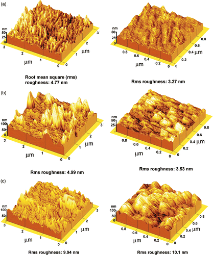
Experiments show that the growth modes of PANi layers on glass and alumina substrates depend on synthesis conditions (says, the synthesis time, mechanical agitation, etc). From relevant SEM images, three typical structures: fibrillar, plannar and granular have been observed as shown in . As can be seen from the images in , a smooth surface PANi thin film (plannar structure) is formed in the reaction solution which is mechanically agitated while a rough surface PANi layer agglomerated with grain and rod-like structure (granular and fibrillar) is created in a still reaction solution. On the other hand, the fibrillar structure is affected by reaction time. As the synthesis time is prolonged, the rod-like structure (fibrillar) is elongated, i.e. the mean length is increased. However, the cross-section of PANi rods and the mean size of PANi grain (granular structure) is not much changed (). In order to have an insight into the PANi layer structure, Alpha-Step IQ measurements and AFM images were made. The topography, roughness and thickness of the PANi layers are shown in and . The roughness of the PANi layer synthesised by mechanical agitation is less in accordance with a smooth surface as shown in SEM image. On the other hand, the PANi layer formed under still condition is more agglomerate and its roughness increases with synthesis times. However, as can be seen from the Alpha-Step IQ images, the thicknesses of the films are unchanged (a base layer of around 90 nm). From the chemical viewpoint, it can be assumed that at the starting stage of polymerisation the substrate surface acts as a nucleation site for radical aniline monomers to anchor on the substrate surface Citation8,Citation9. Under mechanical agitation, the secondary growth is likely to be suppressed and a smooth PANi layer of fine grains (granular structure) is formed. Without mechanical agitation, the secondary growth takes place preferably along the PANi chain resulting in a fibrillar structure.
Figure 1. PANi thin film growth modes on glass plate emerged in reaction solution: (0.10M ANi, 0.12 APS, 1.0M HCl; (a) 15 min (mechanical agitation) (b) 15 min (no agitation), (c) 30 min (no agitation)).
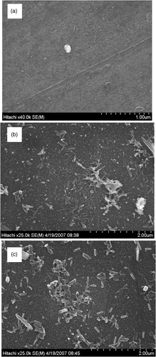
Figure 2. 2D topography, microroughness and the height of PANi thin film made by in situ chemical polymerisation. (a) 15 min (mechanical agitation) (b) 15 min (no agitation), (c) 30 min (no agitation).
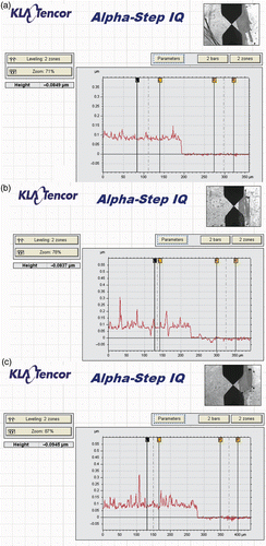
Figure 3. AFM images of PANi thin film growth on glass (a) 15 min (mechanical agitation) (b) 15 min (no agitation), (c) 30 min (no agitation).
Raman spectra made on the PANi layer () show the presence of the vibration bands characterising PANi emeradine. According to the Raman assignment of PANi shown in , the band in the region of 1500 cm−1 is due to the benzenoid (B) ring stretching vibration, the band near 1600 cm−1 is related to the quinoid (Q) structure, the 1170 cm−1 band is assigned to a vibration mode of B–NH=Q structure. The band at 1170 cm−1 is attributed to an electronic-like band and is considered as a measure of the degree of delocalisation of electrons. The most striking point observed in Raman spectra is the variation in the intensity of adsorption band around 1320 cm−1, which is assigned for C–N+ stretching mode (semiquinoid form). The variation in 1320 cm−1 band intensity indicates the fact that depending on synthesis condition the PANi undergoes a change from the quinoid to the benzennoid form, i.e. being in the protonation state. The 1320 cm−1 band first relates to the polaron lattice and then relates to the pristine conductance of the PANi Citation11,Citation13. As can be seen from , the samples synthesised under mechanical agitation () and with longer synthesis time () have higher degree of protonation than that of the sample synthesised with shorter synthesis time and under still condition (). The agitation and synthesis time may affect the amount of counteranion (acidic radical) attached along the polymer chain and then the degree of protonation. Consequently, the stronger 1320 cm−1 band the PANi layer has, the lower will be its pristine resistance (inversely proportional to the conductance) ().
Figure 4. Raman spectrum of PANi thin film growth on glass. (a) 15 min (mechanical agitation) (b) 15 min (no agitation), (c) 30 min (no agitation).
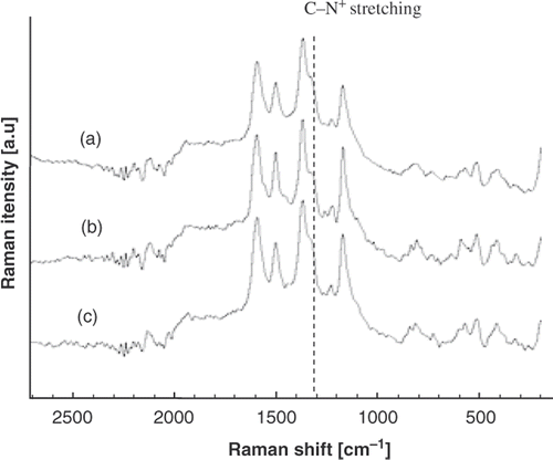
Table 1. Raman assignments of PANi.
Table 2. Pristine resistance, air and NH3 gas sensitivity of PANi layers: (a) 15 min (mechanical agitation), (b) 15 min (no agitation) and (c) 30 min (no agitation).
The conductance of the PANi layer is sensitive to oxidising agent (such as O2) and reducing agent (NH3). shows the resistance of the PANi layer synthesised without mechanical agitation in 15 min as a function of air pressure. The change in PANi layer conductance is accounted for the physical adsorption of oxygen (an oxidising agent) which is available in air. The adsorption creates shallow levels in PANi band gap (chemical or physical doping). Consequently, PANi behaves as p-type semiconducting materials in open air and its conductance varies with oxygen concentration (de-doped or doped) as air pressure changing. The addition of the other active gases may give rise to a similar manner. As an example, upon exposure to a reducing agent such as NH3 gas the resistance of PANi layer will increase. The reduction of free carriers (holes) due to the addition of electrons from adsorbed NH3 molecules into valence band of PANi p-type semiconductor is accounted for the increase in resistance. The typical NH3 gas sensing profile of the PANi synthesised without mechanical agitation in 15 min is shown in . As can be seen from the figure, the resistance of PANi layer is almost proportional to NH3 gas concentration. From the physical viewpoint, the sensitivity depends on the PANi layer nature and the interaction between gas molecules and PANi chain. The synthesis condition modifies the PANi electronic structure while the gas molecular-PANi interaction alters either the free charge density or the charge transportation in the PANi layer. summarises the pristine and sensitivity of samples prepared under different condition. The relevant data shows that the sensitivity is somewhat correlated to the pristine resistance, i.e. the sample with larger resistance has higher sensitivity. NH3 molecules–PANi interaction may alter the protonation state of the PANi layer. The sensing effect is considered to be taken at the base layer whose thickness is the same. The smooth surface of the 15 min agitation sample allows a shallow diffusion path of NH3 molecules then reduces the effective exposed surface area, while the agglomerate surface of the 30 min non-agitation sample prevents NH3 molecules approaching to the surface of base line. As a result, both the samples show lesser sensitivity than the 15 min non-agitation sample.
Figure 5. Resistance of PANi sample (15 min no agitation) as a function of air pressure (P: pump on, O: open).
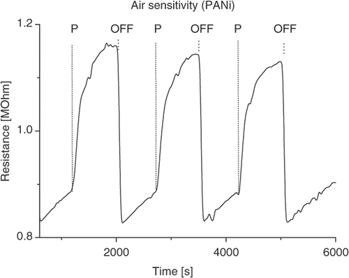
Figure 6. Sensitivity profile of PANi sample (15 min no agitation) as a function of NH3 concentration.
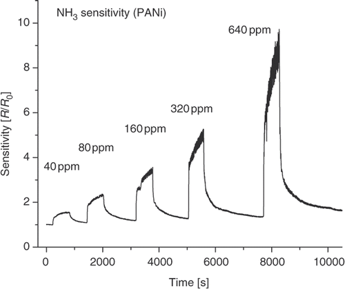
In this work, the NH3 sensitivity of PANi layer made by in situ chemical polymerisation is comparable to that of PANi layer made by emulsion polymerisation Citation12 and relatively lower than that of casting fibrillar PANi layer Citation14. However, its sensitivity is found to be higher than that of casting electrochemically polymerised PANi layer Citation15. The difference in porous structure, exposed active surface area, results in the difference in sensitivity.
4. Conclusion
The PANi nanolayer formed on the surface of glass and alumina substrate by in situ chemical polymerisation is investigated and discussed. It has been found that, the surface morphology, the thickness of the PANi layer remarkedly depends on the synthesis conditions. The mechanical agitation affects the growth mode (planar, granular or fibrillar structure) of the PANi layer. As results of porosity and largely exposed active surface area, the in situ chemically polymerised PANi layers exhibit high sensitive to oxygen pressure and NH3 gas. The improvement enables the in situ chemically polymerised PANi nanolayer effective sensing materials for gas sensors activated at room temperature.
References
- Green , AG and Woodhead , AE . 1910 . Aniline-black and allied compounds: Part I . J. Chem. Soc. , 97, : 2388 – 2403 .
- Green , AG and Woodhead , AE . 1912 . Aniline-black and allied compounds Part II . J. Chem. Soc. , 101, : 1117 – 1123 .
- Diaz , AF and Logan , JA . 1980 . Electroactive polyaniline films . J. Electroanal. Chem , 111 : 111 – 114 .
- MacDiarmid , AG and Epstein , AJ . 1989 . Polyanilines: A novel class of conducting polymers . Faraday Discuss. Chem. Soc. , 88 : 317 – 332 .
- Skotheim , TA and Reynolds , JR . 2007 . Handbook of Conducting Polymer, Vol. I, Theory, Synthesis, Properties and Characterization, Vol. II, Processing and Application, , 3rd edn , Boca Raton : CRC Press .
- Han , MG , Cho , SK , Oh , SG and Im , SS . 2002 . Preparation and characterization of polyaniline nanoparticle synthesized from DBSA micellar solution . Synth. Met. , 126 : 53 – 60 .
- Kinlen , PJ , Frushour , BG , Ding , Y and Menon , V . 1999 . Synthesis and characterization of organically soluble polyaniline and polyaniline block copolymers . Synth. Met. , 101 : 758 – 761 .
- Kim , B-J , Oh , S-G , Han , M-G and Im , S-S . 2001 . Synthesis and characterization of polyaniline nanoparticles in SDS micellar solutions . Synth. Met. , 122 : 297 – 304 .
- Kohut-Svelko , N , Reynaud , S and François , J . 2005 . Synthesis and characterization of polyaniline prepared in the presence of nonionic surfactants in an aqueous dispersion . Synth. Met. , 150 : 107 – 114 .
- Stejskal , J and Sapurina , I . 2001 . Polyaniline-coated silica gel . J. Euro. Pol. , 38 : 631 – 637 .
- Sapurina , I , Riede , A and Stejskal , J . 2001 . In-situ polymerized polyaniline films 3: Film formation . Synth. Met. , 123 : 503 – 507 .
- Li , D and Kaner , RB . 2006 . Shape and aggregation control of nanoparticles: Not shaken, not stirred . J. Am. Chem. Soc. , 128 : 968 – 975 .
- Zhao , P , Gerhard , EN , Helmut , N , Johannes , T and Adolf , N . 1997 . Protonation and electrochemical redox doping processes of polyaniline in aqueous solutions: Investigations using in situ FTIR-ATR spectroscopy and a new doping system . J. Chem. Soc., Faraday Trans. , 93 ( 1 ) : 121 – 129 .
- Wu , S , Zeng , F , Li , F and Zhu , Y . 2000 . Ammonia sensitivity of polyaniline films via emulsion polymerization . Eur. Pol. J. , 36 ( 4 ) : 679 – 683 .
- Stafstrom , S , Bredas , JD , Epstein , AJ , Woo , HS , Tanner , DB , Hwang , VS and MacDiarmid , AG . 1987 . Polaron lattice in highly conducting polyaniline: Theoretical and optical studies . Phys. Rev. Lett. , 59 : 1464 – 1467 .
- Huang , JX , Virji , S , Weiller , BH and Kaner , RB . 2004 . Polyaniline nanofiber sensors . Chem. Eur. J. , 10 ( 6 ) : 1314 – 1319 .
- Huyen , DN , Minh , LH and Chien , ND . 2005 . “ Electrochemically synthesized polyaniline for gas sensing material. ” . In Proceedings of 12th ASEAN Symposium on Chemical Engineering–RSCE 2005 , Vol. 4 , 30 – 34 . New Trends in Technology towards Sustainable Development .