
 ?Mathematical formulae have been encoded as MathML and are displayed in this HTML version using MathJax in order to improve their display. Uncheck the box to turn MathJax off. This feature requires Javascript. Click on a formula to zoom.
ABSTRACT
Design for disassembly using deconstructable connections facilitates recycling and reusing of building materials and, therefore, reduces waste management problems at the end of service life. In this regard, a deconstructable timber-concrete composite connector using self-tapping screws has been developed at Aalto University. In the presented research, an experimental investigation was performed to further evaluate the effectiveness of this connector in fabricating deconstructable cross-laminated timber (CLT)-concrete composite floors. For this purpose, several CLT-concrete composite beams were fabricated using 5-layer CLT and low-shrinkage concrete. Each beam contained one row of connectors to represent a strip of a full-scale floor. The vibration performance, bending properties, interface slip, failure modes, and ease of disassembly of the beams were investigated. The results were compared with the ones from a reference group of beams fabricated with regular screws. Overall, the deconstructable beams performed exceptionally well by attaining 98.5% of the average bending stiffness of the regular beams. The load-carrying capacity was also similar but governed by the CLT plate. The vibration characteristics were comparable in both groups. After the bending test, the deconstructable beams were disassembled. Although the beams had been exposed to unproportionally large deformations under the bending load, the disassembly process was performed successfully.
Introduction
During the last decade, concerns regarding global climate change have created an opportunity to further increase the use of timber materials in the built environment, including for application in structural floor systems. In this regard, floor systems made with laminated timber products such as cross-laminated timber (CLT) have exhibited less environmental impacts than conventional concrete floors (Hassan et al. Citation2019). However, timber floors in general can be more susceptible to serviceability issues due to the lighter weight and the lower stiffness (e.g. Jiang and Crocetti Citation2019, Mirdad et al. Citation2021, Jaaranen and Fink Citation2022). An effective method to address these issues is to use a timber-concrete composite (TCC) solution. TCC is more environmentally friendly than traditional concrete floors and offers structural advantages compared to timber floors. In TCC, usually a relatively thin concrete topping is connected to a timber component using shear connectors. The resulting composite system takes advantage of the high compressive capacity of concrete and the high tensile capacity of timber (Yeoh et al. Citation2011, Dias et al. Citation2016). In order to achieve the full potential of the composite action, the connectors need to be designed with satisfactory shear stiffness. One drawback of TCC floors, however, is that the conventional shear connections used in their construction are predominantly made with permanent connectors that cannot be disassembled. This represents a challenge for the disposal of the buildings and can lead to waste management problems at the end of service life.
Some of the connection systems that were investigated in the previous studies have the potential of being deconstructed (see Lukaszewska et al. Citation2008, Lukaszewska Citation2009, Fragiacomo and Lukaszewska Citation2013, Citation2015, Crocetti et al. Citation2015, Zhang et al. Citation2019, Shi et al. Citation2021). However, the focus of these studies was on the connections that can enable the prefabrication of TCC floors in the dry-dry construction system, and therefore, the deconstructability was not the primary subject. In the dry-dry system, the concrete slab is prefabricated and then connected to the timber component using screw connectors. The screws can be inserted through e.g. steel/plastic tubes (Crocetti et al. Citation2015), wooden blocks (Khorsandnia et al. Citation2016), or steel plates (Shi et al. Citation2021) that are pre-embedded in the concrete. A few other deconstructable solutions were also investigated by Khorsandnia et al. (Citation2016, Citation2018), in which the deconstructability of TCC floors was specifically investigated. The proposed solutions are suitable for the prefabrication of TCC floors in a joisted system.
The dry-dry system offers a wide range of benefits, however, direct concrete casting (i.e. wet-dry construction system) is currently the dominant approach in fabricating TCC structures. In this regard, Thai et al. (Citation2020) investigated a deconstructable connection for CLT-concrete composite floors fabricated in the wet-dry system. The proposed connection was a rectangular notch reinforced with two self-tapping screws. Pang et al. (Citation2022) also investigated the bending properties of a separatable CLT-concrete composite floor in the wet-dry system. The composite elements were fabricated using round notch connections, however, without the use of screw reinforcement.
Recently, a deconstructable connector was also developed at Aalto University that is suitable for both dry-dry and wet-dry construction systems (Derikvand and Fink Citation2021). The connector can be applied on different TCC floor types as well, and therefore, offers a higher level of versatility than most of the existing solutions. The connector is made of a self-tapping screw whose upper section is covered with a thin protective layer and a lid. The initial trials exhibited sufficient shear properties under static push-out loads. However, so far, the performance of the connector has been evaluated and approved only at the connection level, meaning by performing shear tests on individual connectors. Therefore, in the herein presented research, an experimental investigation was performed to further evaluate the effectiveness of this connector in fabricating deconstructable CLT-concrete composite floors. This was done by testing strips of a CLT-concrete composite floor. Each strip (referred to as composite beam) contained one row of connectors. The fundamental frequency, damping ratio, bending properties, interface slip, and failure modes of the composite beams were investigated. In order to qualitatively evaluate the efficiency of the connector an additional group of composite beams made with regular self-tapping screws were also fabricated and tested as reference. In addition to the mechanical properties, the deconstructability after large deformations was investigated. Therefore, the composite beams fabricated with the deconstructable connector were disassembled after the destructive bending test.
Materials and methods
Specimen
Five CLT-concrete composite beams were fabricated using the deconstructable connector and five composite beams were fabricated using the equivalent regular self-tapping screw. The configuration and dimensions of the composite beams can be seen in .
Figure 1. The configuration of the CLT-concrete composite beams and the four-point bending test set-up. Measurements in mm.
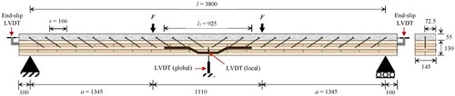
A 5-layer CLT plate, made of Spruce boards with the strength class of C24 (EN 338 Citation2016), was purchased from a local supplier and used to fabricate the composite beams. The CLT plate had been produced without narrow face bonding. The heights of the longitudinal and the transvers layers were h1,3,5 = 30 mm and h2,4 = 20 mm, respectively. A total of ten CLT beams with the dimensions of b × h × l = 145 × 130 × 4000 mm3 were used to fabricate the CLT-concrete composite beams. It should be noted that, due to the small width of the CLT beams, the load carrying capacity of the CLT-concrete composite elements is expected to be highly influenced by the properties of the individual timber boards as well as the quality and position of the finger joints. Resulting from the small width, the system effect is significantly reduced, and therefore, the load carrying capacity of the composite beams may not be representative for a full-scale CLT-concrete composite floor. However, in this study the focus is on the serviceability performance, and therefore, the specimens are assumed to be suitable. Prior to fabricating the CLT-concrete composite elements, the local bending stiffness and the effective bending stiffness of the CLT beams were measured experimentally in accordance with EN 408 (Citation2010). For this purpose, the beams were loaded within the elastic range using the four-point bending test set-up shown in . Based on the measured stiffness values, the CLT beams were subdivided equally into two groups, one group for the fabrication of the deconstructable composite beams and one group for the fabrication of the regular composite beams.
A low-shrinkage concrete was selected for the fabrication of the composite beams. The proportion of different components in the concrete mix can be seen in . The density and the 28 day compressive strength of the concrete was measured in accordance with EN 12390-3 (Citation2019). This was performed by testing ten cubic samples with the dimensions of b × h × l = 100 × 100 × 100 mm3, which were taken from different concrete batches in the study. The cubic samples were stored in the same environment as the composite beams so that a relevant estimation of the compressive strength of the slab can be obtained.
Table 1. The concrete mix proportion used in the study.
The deconstructable composite beams were fabricated using the connector illustrated in . The connector is comprised of a self-tapping screw covered in the upper section using a thin layer of heat-shrink tubing (HST) and a lid made of Styrofoam. The full description of the connector details, including its application process and its shear properties, can be found in Derikvand and Fink (Citation2021). In the present study, however, the connector is slightly modified. In Derikvand and Fink (Citation2021), the entire length of the screw in the concrete section was covered by the HST layer, whereas in the present study only half of the length of the screw in the concrete section is covered (). This modification was made to create a timber-concrete interface configuration that would be similar to that in a regular TCC connection with self-tapping screw. Furthermore, the upper section of the connector lid was cut with 30° angle (see ), which was equal to the screw insertion angle chosen in this study. This way the top surface of the lid will be parallel to the top surface of the concrete.
Figure 2. Configuration of the deconstructable connector.
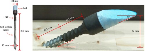
To fabricate the composite beams, the connectors were driven into the centerline of the CLT using predrilled holes Ø = 8 mm. The insertion angle α = 30°, the spacing of the connectors s = ∼166 mm, and the penetration depth in the CLT section lef = 125 mm. After the screw insertion process, a plywood formwork was installed around the beams and a steel wire mesh (Ø = 8 mm) was placed inside the formwork. The concrete was then cast. The concrete height hc≈55 mm, whereas the height of the connector after installing was about 52 mm (). Therefore, a 3 mm-thick concrete layer covered the lid of the deconstructable connector. As a result, the deconstructable and the regular composite beams were visually identical from every angle. The composite beams were kept in the laboratory environment for 28 days prior to the vibration and the bending tests.
Vibration test
After 28 days, the plywood formworks were opened and the composite beams were placed on a simply supported set-up as shown in . The vibration test was then performed using a modal impact hammer, an accelerometer, a charge amplifier, and a dynamic signal analyzer. The accelerometer was installed under the beam at 1520 mm distance from the nearest support. The impact was applied on the centerline of the concrete top surface on 11 different points along the span. The data were recorded using Data Physics SignalCalc Software and further processing of the data was performed in MATLAB.
Four-point bending test
The composite beams were tested to failure point using the four-point bending set-up shown in . The loading conditions were set in accordance with EN 408 (2010) so that the failure point can be reached within 300 ± 120 sec. The test was ceased after the failure point when the load level dropped to 70% of the maximum load (Fmax). The midspan global deflection was measured from the center of the bottom layer of the CLT component using a linear variable differential transformer (LVDT). The local deflection was measured also at the midspan using two LVDTs installed on both sides of the composite beams. The slips at the CLT-concrete interface were measured from the cross-section of the composite beams at both ends.
Results and discussion
Vibration performance
The fundamental frequency (f) and the damping ratio (ζ) of the composite beams are given in . On average, the fundamental frequency of the deconstructable composite beams was only 2.1% lower than that of the regular ones. The damping ratio was marginally higher for the deconstructable group. Nevertheless, given the general uncertainties and sensitivity of this type of measurement, the damping ratio could be considered similar in both groups.
Table 2. Test results of the CLT beams and the composite beams: Vibration characteristics, bending properties, and failure modes.
Bending performance
Load-deflection curves and failure modes
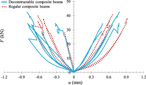
The load-deflection curves of the deconstructable and the regular composite beams can be seen in . Although the load levels vary between individual composite beams, no distinguished difference can be observed in the load-deflection trends in the two groups. The connector type did not show a noticeable effect on the average load carrying capacity (Fmax) of the composite beams (). This was expected to be achieved as the shear strength of this connector system has shown to be only marginally lower than that of the equivalent regular self-tapping screws (see Derikvand and Fink Citation2021). As mentioned earlier, due to the small width of the composite beams, the load-carrying capacity was influenced by the performance of the individual lamellae as well as the quality and location of the finger joints. Resulting from the small width, the system effect was reduced, and therefore, the maximum load carrying capacities that were obtained in the study may not be representative for a full-scale CLT-concrete composite floor. Nevertheless, the focus of the present study is on the serviceability of the floor elements.
Figure 3. The load-deflection curves of the composite beams under four-point bending.

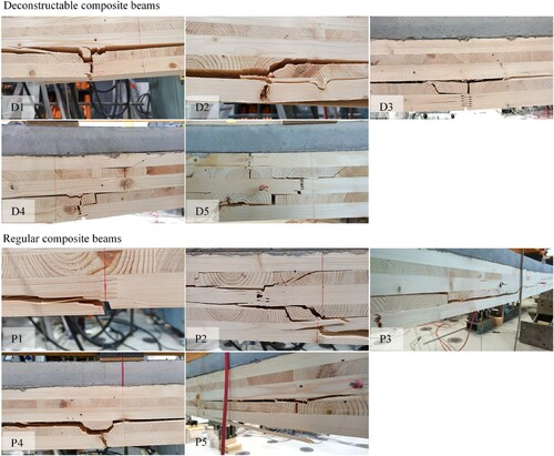
In both groups, the governing failure mode was finger joint failure (). The failures initiated in the finger joints or in the knots located in the bottom lamella and then propagated to the next layers. Similar failure modes have been reported by Mai et al. (Citation2018) for TCC slabs fabricated with 5-layer CLT. In three composite beams, the concentration of multiple finger joints and knots in one location resulted in nearly complete fracture of the CLT section. This led to crack development in the tension side of the concrete part, as indicated in . No gap opening was observed between the CLT and the concrete in any of the composite beams.
Figure 4. Failure modes of the composite beams.
Bending stiffness
The local bending stiffness (EIlocal) was calculated using Equation (1) and the effective bending stiffness (EIeff) was calculated using Equation (2); where, is the slope of the load-deflection curve from 0.1 Fmax to 0.4 Fmax, and a, l, and l1 are the geometrical characteristics as defined in . The test results are summarized in .
(1)
(1)
(2)
(2) The average values of the local bending stiffness were quite similar in both groups; however, the effective bending stiffness is more often used as the main reference for comparing TCC beams. On average, the deconstructable composite beams achieved 98.5% of the effective bending stiffness of the regular composite beams. The coefficient of variation (COV) was only 3.3% for the deconstructable composite beams and only 4.4% for the regular once. The stiffness differences are significantly smaller compared to the once found in the previous investigation at the connection level (Derikvand and Fink Citation2021); there, the deconstructable connector inserted at α = 30° had exhibited ∼12.7% less average shear stiffness than the equivalent regular self-tapping screws. However, as described earlier, in the present study only half of the screw length in the concrete section was covered by the HST layer, which might have contributed to the improvement in the shear stiffness of the connector.
CLT-concrete interface slip
The slip at the CLT-concrete interface was used to further evaluate the performance of the deconstructable connectors. Overall, the load-slip trends in the deconstructable and the regular composite beams appeared to be comparable ().
Figure 5. The load-slip curves at the left and the right ends of the composite beams.
In most beams, a larger slip in the initial phase followed by a linear trend was obtained in the load-slip curves, which was similar for both test groups. This effect was different compared to the load-slip curves observed for other forms of TCC elements in some of the previous studies e.g. Crocetti et al. (Citation2015), Khorsandnia et al. (Citation2016), and Zhang et al. (Citation2019); in these studies, however, the slips were measured from the side of the specimens rather than the cross section. Based on the observations during the test in the present study, one reason for the larger slip in the initial phase could be the initial gap closing between the CLT and the concrete at the beginning of the test, which causes additional outward movement of the slab at the cross-section. These small gaps were caused by the concrete shrinkage and were most noticeable at the cross-section of the composite beams and above the supports. In those cases (D3 and P5) where the gaps were minimal, the load-slip trends seemed to be more typical as can be observed in . For a more detailed investigation about the effect of the interface slip, however, further aspects such as the friction between the timber and the concrete component also need to be considered (see e.g. Jaaranen and Fink Citation2020 Citation2021). This, however, is outside the scope of the present study.
Overall, the highest slip values at Fmax in the deconstructable and the regular composite beams were u = 0.81 mm and u = 0.92 mm, respectively. Based on results reported by Derikvand and Fink (Citation2021), the maximum load-carrying capacity of the deconstructable connector is reached at u > 1.7 mm. Therefore, the deconstructable connectors presumably had not yet reached their maximum capacity when the composite beams failed under the bending load. Nevertheless, this effect was similar for both connector types.
Ease of disassembly
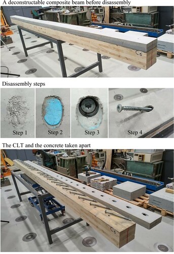
After completing the bending tests, the ease of disassembly of the deconstructable composite beams was evaluated by removing the screws. Each screw was removed in four steps as depicted in and further described in the following. Step1: the thin concrete layer on top of the connector lid was broken using a light hammer. It is important to note that the presence of the connector holes inside the concrete of the deconstructable beams did not appear to cause any specific cracks or damages in the concrete section. Step 2: the broken concrete was wiped off using a hand brush so that the connector lid become visible. Step 3: the lid was taken out so that the screw can be accessed. Step 4: the screw was removed using a cordless screwdriver. The CLT and the concrete slab were taken apart after removing all the screws. It was observed that the disassembly process of a deconstructable composite beam, consisting of 22 connectors, can be completed without any difficulty in around 15 min. This was possible since the screws did not develop any major plastic hinge during the bending test.
Figure 6. Deconstruction process of one of the composite beams after the bending test.
It should be noted that Step 1 and Step 2 of the disassembly process will not be required if a larger lid is used. In this case, the top surface of the lid will be visible, and therefore, no concrete layer will form above the connector. However, a thin layer of concrete above the connector will have several benefits. One of the benefits is that the connector hole will not be visible on the concrete surface, and therefore, the surface finish of the concrete will be similar to that in a regular TCC. This could be important for e.g. the installation of the architectural components of the floor at the later stages of the construction. The thin concrete layer can also create some protection for the connections.
Properties of the materials
The local bending stiffness and the effective bending stiffness of the CLT beams in each group were calculated using Equation (1) and Equation (2), respectively. The results can be seen in . The average density and the average 28 day compressive strength of the concrete were ρc = 2358.6 kg/cm2 (COV = 5%) and fc = 58.8 MPa (COV = 3.9%).
Conclusions
In this study, the effectiveness of a recently developed deconstructable connector made with self-tapping screw was evaluated for the fabrication of deconstructable CLT-concrete composite floors. Several composite beams were fabricated using the connector and their vibration performance, bending properties, interface slip, failure modes, and ease of disassembly were studied. A reference group of composite beams made with regular self-tapping screws were also fabricated and tested to create a basis for comparison. The following conclusions were drawn based on the results:
The difference in the natural frequency of the deconstructable and the regular composite beams was negligible. The damping ratio was marginally higher in the deconstructable group.
The deconstructable composite beams attained around 98.5% of the average effective bending stiffness of the regular once. Therefore, no important difference was distinguished in the bending stiffness.
A larger slip in the initial phase followed by a linear trend was observed in the load-slip curves of the CLT-concrete interface at the ends of beams, which was similar in both groups. The reason for this effect could be the initial gap closing between the CLT and the concrete at the cross-section of the composite beams during the bending test.
The deconstructability of the composite beams after large deformations under the bending load was approved. The deconstruction was still possible because the connectors inserted at α = 30° had not developed any detectable plastic hinge.
Overall, the results of this study indicate that the CLT-concrete composite floor beams fabricated with the new connector can provide similar mechanical properties to the ones fabricated using the regular self-tapping screws. Therefore, the new connector can be an alternative solution in fabricating more ecofriendly TCC structures. Nevertheless, it must be noted that the excessive use of steel materials in the connectors can have a negative environmental impact on its own. Therefore, the full potential of this deconstructable solution can be achieved if the number of connectors in the floor system is reduced. This can be done in several ways without compromising the structural capacity of the floor e.g. by combining the new connector with a notch connector. Nevertheless, it was essential in this study to only use the connectors in their pure forms because this way any difference between the capacities of the new connector and the regular screws could be observed more clearly.
Acknowledgements
The authors are grateful to Joonas Jaaranen (from Aalto University) for his input and assistance during the vibration test.
Disclosure statement
No potential conflict of interest was reported by the author(s).
References
- Crocetti, R., Sartori, T. and Tomasi, R. (2015) Innovative timber-concrete composite structures with prefabricated FRC slabs. Journal of Structural Engineering, 141(9), 04014224.
- Derikvand, M. and Fink, G. (2021) Deconstructable connector for TCC floors using self-tapping screws. Journal of Building Engineering, 42, 102495.
- Dias, A. M. P. G., Skinner, J., Crews, K. and Tannert, T. (2016) Timber-concrete-composites increasing the use of timber in construction. European Journal of Wood and Wood Products, 74(3), 443–451.
- EN 408. (2010). Timber structures – Structural timber and glued laminated timber – Determination of some physical and mechanical properties. European Committee for Standardization.
- EN 338. (2016). Timber structures-strength classes. European Committee for Standardization.
- EN 12390-3. (2019). Testing hardened concrete-Part 3: Compressive strength of test specimens. European Committee for Standardization.
- Fragiacomo, M. and Lukaszewska, E. (2013) Time-dependent behaviour of timber–concrete composite floors with prefabricated concrete slabs. Engineering Structures, 52, 687–696.
- Fragiacomo, M. and Lukaszewska, E. (2015) Influence of the construction method on the long-term behavior of timber-concrete composite beams. Journal of Structural Engineering, 141(10), 04015013.
- Hassan, O. A., Öberg, F. and Gezelius, E. (2019) Cross-laminated timber flooring and concrete slab flooring: A comparative study of structural design, economic and environmental consequences. Journal of Building Engineering, 26, 100881.
- Jaaranen, J. and Fink, G. (2020) Frictional behaviour of timber-concrete contact pairs. Construction and Building Materials, 243, 118273.
- Jaaranen, J. and Fink, G. (2021) Cohesive-frictional interface model for timber-concrete contacts. International Journal of Solids and Structures, 230-231, 111174.
- Jaaranen, J. and Fink, G. (2022) Experimental and numerical investigations of two-way LVL-concrete composite plates with various support conditions. Engineering Structures, doi:10.1016/j.engstruct.2022.114019
- Jiang, Y. and Crocetti, R. (2019) CLT-concrete composite floors with notched shear connectors. Construction and Building Materials, 195, 127–139.
- Khorsandnia, N., Valipour, H., Schänzlin, J. and Crews, K. (2016) Experimental investigations of deconstructable timber–concrete composite beams. Journal of Structural Engineering, 142(12), 04016130.
- Khorsandnia, N., Valipour, H. and Bradford, M. (2018) Deconstructable timber-concrete composite beams with panelised slabs: Finite element analysis. Construction and Building Materials, 163, 798–811.
- Lukaszewska, E. (2009) Development of prefabricated timber-concrete composite floors. Doctoral dissertation. Luleå tekniska universitet.
- Lukaszewska, E., Johnsson, H. and Fragiacomo, M. (2008) Performance of connections for prefabricated timber–concrete composite floors. Materials and Structures, 41(9), 1533–1550.
- Mai, K. Q., Park, A., Nguyen, K. T. and Lee, K. (2018) Full-scale static and dynamic experiments of hybrid CLT–concrete composite floor. Construction and Building Materials, 170, 55–65.
- Mirdad, M. A. H., Daneshvar, H., Joyce, T. and Chui, Y. H. (2021) Sustainability design considerations for timber-concrete composite floor systems. Advances in Civil Engineering, 2021.
- Pang, S. J., Ahn, K. S., Jeong, S. M., Lee, G. C., Kim, H. S. and Oh, J. K. (2022) Prediction of bending performance for a separable CLT-concrete composite slab connected by notch connectors. Journal of Building Engineering, 49, 103900.
- Shi, B., Liu, W. and Yang, H. (2021) Experimental investigation on the long-term behaviour of prefabricated timber-concrete composite beams with steel plate connections. Construction and Building Materials, 266, 120892.
- Thai, M. V., Ménard, S., Elachachi, S. M. and Galimard, P. (2020) Performance of notched connectors for CLT-concrete composite floors. Buildings, 10(7), 122.
- Yeoh, D., Fragiacomo, M., De Franceschi, M. and Heng Boon, K. (2011) State of the art on timber-concrete composite structures: Literature review. Journal of Structural Engineering, 137(10), 1085–1095.
- Zhang, Y., Raftery, G. M. and Quenneville, P. (2019) Experimental and analytical investigations of a timber–concrete composite beam using a hardwood interface layer. Journal of Structural Engineering, 145(7), 04019052.