
 ?Mathematical formulae have been encoded as MathML and are displayed in this HTML version using MathJax in order to improve their display. Uncheck the box to turn MathJax off. This feature requires Javascript. Click on a formula to zoom.
ABSTRACT
In this paper, an adaptable and architecturally flexible lateral stiffening system for tall timber buildings between 50 and 147 m is developed and investigated. The system is based on a tube-in-tube concept. The internal tube consists of a braced timber core, and the external tube consists of a frame structure with semi-rigid beam-column joints in the façade. Based on a finite element framework, more than 500 000 simulations with different configurations are carried out to assess the performance of the lateral stiffening system subjected to wind loading. The resulting data is used to assess the feasibility of the tube-in-tube system and stiffness requirements for the beam-column joints.
Introduction
In the twentieth century, buildings in steel and reinforced concrete saw rapid technological and engineering advancements. This enabled the construction of ground-breaking new tall buildings (Tamboli Citation2014). At present, a similar advancement for tall timber buildings is underway with several new records being broken in recent years. In 2009, the 30 m tall 9-storey cross-laminated timber (CLT) building Stadthaus was built in the UK. This was followed by buildings such as the 10-storey Forte-Tower in Australia in 2013, the 14-storey Treet in Norway in 2015, the 18-storey Brock Commons in Canada in 2017 and the 19-storey Sara Kulturhus in Sweden in 2021. At present, the two tallest timber buildings are in Europe, namely HoHo in Austria with a height of 84.0 m (Woschitz and Zotter Citation2017), and Mjøstårnet in Norway with a height of 85.4 m (Abrahamsen Citation2018). Several other tall timber buildings have also been constructed (Torem and Safarik Citation2020).
With ever-increasing building heights in tall timber buildings, the lateral stiffness is becoming more important. Stresses due to wind loading increase with the building height and wind-induced vibrations is often the governing design criterion for tall buildings. Therefore, wind loading often dictates the design of the lateral stiffening system of the structure. Several investigations on the dynamic response of tall timber buildings subjected to wind-induced vibrations have been carried out in the past decade. Reynolds et al. (Citation2011) highlighted the impact of different aspects of the dynamic behaviour of tall timber buildings. Johansson et al. (Citation2015) reviewed the dynamic response and wind loading of a few medium-rise timber buildings according to EN Citation1991-Citation1-Citation4 (Citation2010). Schmid et al. (Citation2018) compared the lateral stiffness of timber buildings with an internal reinforced concrete core against an internal CLT-core for buildings between 40 and 200 m tall and logarithmic decrements δs of 0.05 and 0.10. Johansson et al. (Citation2016) carried out a preliminary study of wind-induced vibrations of a 22-storey CLT-building.
Currently, the predominant structural system for tall timber buildings is a timber-concrete hybrid where the lateral stiffness is provided by a relatively stiff reinforced concrete core. This can be observed in Brock Commons in Vancouver, Arbo in Switzerland, Haut in the Netherland, HoHo in Austria, or Ascent in USA, to mention some buildings. To decrease the carbon footprint of the buildings, there is a strong incentive to reduce the use of reinforced concrete by introducing lateral stiffness concepts in timber. Besides the promotion of a reduced carbon footprint, other major advantages are the potential for a dry and fast construction period and reduction of wide differences in tolerances between different construction materials.
At present, one of the main challenges in timber engineering is the lack of sufficiently stiff joints. Timber lacks strength and stiffness perpendicular to the grain and can only be subjected to high loads parallel to the grain. Therefore, the load transfer from beams to columns are particularly difficult for mechanical or glued joints due to the change in the loaded grain direction. The behaviour of the joint can be viewed as a joint between a material with strong mechanical properties and another with weak mechanical properties. Furthermore, the effects of long-term behaviour such as creep complicate the stiffness and load-bearing capacity of moment-resisting or semi-rigid joints.
Tall timber buildings are often designed as a column-beam-slab frame where the lateral stiffness is provided in a central core. The frame itself is only designed for vertical loads with simply supported beam-column joints. By introducing semi-rigid beam-column joints, the frame may be able to contribute substantially to the lateral stiffness of the structure if it is activated. However, moment-resisting joints in timber buildings are used with caution unlike steel or reinforced concrete buildings. This is due to the intrinsic material properties, as well as the challenging design of economical moment-resisting joints with high strength and ductility, which need to be easy to assemble. At present, moment-resisting joints are being developed using axially loaded threaded rods. Bainbridge and Mettem (Citation1998), Lippert (Citation2002), Rebouças et al. (Citation2022) and Stamatopoulos et al. (Citation2022) show some recent developments, but no standardized or commercially efficient solutions are currently available, and their development is still in its infancy.
shows some common structural systems. Cao and Stamatopoulus (Citation2021a, Citation2021b) studied the wind-induced vibrations and dynamic properties of Type I. These are skeleton frames with large spans between 6 and 10 m and bays between two and four. The investigations were conducted with and without bracings in the central bays and semi-rigid beam-column joints. Cao and Stamatopoulus (Citation2021a, Citation2021b) assessed the feasibility of the frames by using the serviceability criterion in ISO 10137 (Citation2007) and found that the height limits for such frames are 30 m.
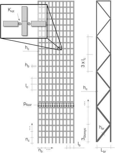
Figure 1. Schematic representation of the investigated structure typologies, based on Fazlur Kahn (Ali and Moon Citation2007) (left) and schematic representation of the tube-in-tube system with its structural behaviour (right).
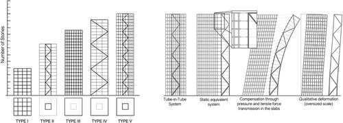
Here, an adaptable and architecturally flexible structural concept based on a tube-in-tube concept is developed and investigated for timber buildings between 50 and 147 m tall. The tube-in-tube concept is a common structural system for tall buildings due to its lateral stiffness properties. It describes a lateral stiffening system consisting of two so-called tubes, where an internal tube is placed within an external tube. The internal and external tubes are connected by floor slabs, which transfer the lateral loads between the external and internal tubes. The shape of the tubes is not constrained to a circular cross-section. In this paper, the tube-in-tube system is defined similarly, but constrained to a rectangular cross-section. In this study, the internal tube consists of a braced timber core, and the external tube consists of a frame structure in the façade. The structural system is illustrated in as Type V as well as the structural behaviour. In this tube-in-tube system, the internal tube resists the lateral loads in a flexural mode and the external tube in a shear mode. The two systems are coupled, which together provide the lateral stiffness of the structure.
Structural system and model
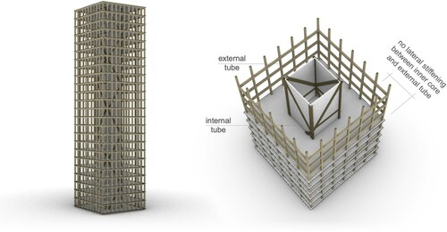
Most buildings are prototypes in the sense that they are unique in their structural concept as well as in their architectural design. However, tall buildings are frequently cuboid volumes with square or rectangular floor plans. In , an illustration of the considered tube-in-tube system in this paper is shown. The floor plan is square with an internal tube and an external tube. The internal tube is a braced timber frame and the external tube is a frame structure. The ratio β between the width of internal tube Lbr and the external tube B is 3. Here, the investigation is focused on the lateral stiffening system and the vertical load transfer is not considered. The mass of the building is assumed to be uniformly distributed along the height of the buildings.
Figure 2. Tube-in-tube system.
The structural analysis and simulations were carried out by adopting and developing the finite element framework for assessing wind-induced vibrations for planar frames developed by Cao and Stamatopoulos (Citation2021a, Citation2021b). In the finite element framework, the trusses and beams use Euler-Bernoulli beam theory and the columns use Timoshenko beam theory. The cross-sections are assumed to be rectangular with a shear correction factor of 5/6 in the columns. The logarithmic decrement of the structural damping is set conservatively to δs = 0.05 in all of the present investigations.
The beam-column joints are idealized as linear-elastic rotational springs with a stiffness Krot, the translational compliance in the joints of the trusses is neglected, and the column-column joints are assumed to be rigid. Thus, the beams span between the columns. The modelled joints do not consider initial slip and other nonlinearities are neglected. The wind-induced vibrations are modelled using the gust factor approach in accordance with EN Citation1991-Citation1-Citation4 Annex B (Citation2010). A schematic of the structural system is shown in .
Figure 3. Structural system (left) and the statically equivalent model for determining the rotational stiffness of the beam-column joint (right).
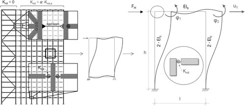
For a rigid beam-column joint, the equivalent rotational spring stiffness Krot,e can be expressed as:
(1)
(1)
where h is the column height, l is the bay length, EIc is the column stiffness and EIb is the beam stiffness, illustrated in . Here, the beam-column joint stiffness Krot is defined as a fraction of the equivalent beam-column joint stiffness Krot,e:
(2)
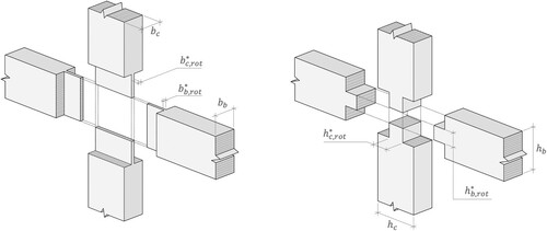
(2) where the stiffness ratio α is between 0.1 and 1.0. The joint stiffness Krot can be illustrated as a reduced cross-section where the beam-column joint is present. The reduction of the cross-section is illustrated in as either a reduction in cross-sectional width or height where the joints are. The cross-sectional reductions can be expressed as:
(3)
(3)
(4)
(4)
Figure 4. Statically equivalent member dimensions representing the approach of the joint stiffness Krot in comparison to the member dimensions.
In the simulations, the global stiffness matrix is reduced to only include its horizontal components by use of static condensation. Vertical and horizontal degrees of freedom in the beam-column joints are assumed to be rigid and have little influence on the horizontal stiffness of framework structures. The local stiffness matrix considers the compliance of the joints according to the formulation of Lui and Lopes (Citation1997) based on static condensation.
The gust factor approach used in EN Citation1991-Citation1-Citation4 (Citation2010) is based on decomposing the frequency-domain response spectrum into a dynamic and transient component. By integrating the response spectrum over the frequency-domain, the standard deviation of the response can be obtained. By multiplying the standard deviation with a peak factor, the peak response of the structure can be found and compared with various design criteria. The peak factor is based on random vibrations theory and is based on an observation period of 10 min in EN Citation1991-Citation1-Citation4 (Citation2010). In the gust factor approach, the standard deviation of the building’s response accelerations can be found from the wind spectrum, logarithmic decrement, aerodynamic admittance function, mass, and various other parameters related to the wind speed and shape of the building. The gust factor approach is widely used in structural codes such as in EN 1991-1-4 and in ASCE/SEI Citation7–Citation22 (Citation2022). More details on the gust factor approach can be found in EN Citation1991-Citation1-Citation4 (Citation2010) or in Cao and Stamatopoulos (Citation2021b).
Parameter study and performance criterion
lists the parameters of the simulations. The calculations are made for each unique combination of the listed parameters. The parameters are the number of floors nc, number of bays nb, bay length lb, member cross-sections bc, hc, bb, hb, bbr, hbr, rotational stiffness ratio of the beam-column joints α, timber grades between GL28h and GL75, and dead loads on the floors pfloor.
Table 1. Overview of the simulation-parameters for the different systems.
The parameters are chosen to cover the most realistic variations of the building geometry. An example is the bay length lb, where a width of 3.6 m is considered particularly flexible architecturally as it can be adopted for both residential and office purposes. The parameters are illustrated in .
Figure 5. Illustration of the parameters.
The basic wind velocity vb,0 is 25 m/s, with subsequent computations based on a 10-year return period with a probability factor cprob of 0.902. The wind computations are based on the gust factor approach for serviceability accelerations described in EN Citation1991-Citation1-Citation4 Annex B (Citation2010). Here, the material parameters and service loads are on the characteristic level.
To assess the feasibility of the buildings, the serviceability criterion in ISO 10137 (Citation2007) based on occupant comfort are used. ISO 10137 (Citation2007) provides a serviceability criterion for wind-induced vibrations of buildings based on peak accelerations. It is derived from measurements of actual buildings in general use. The serviceability criterion is for peak accelerations for offices or residential uses and is a function of the building’s first natural frequency.
Results and discussion
To compare the wind-induced vibrations, the peak accelerations apeak of the tube-in-tube systems are compared with the natural frequency. This is shown in , where the ratio β between the width of the internal tube Lbr and the external tube B is 3.
Figure 6. Comparison of the peak accelerations and the natural frequency fn (left) for the analysed tube-in-tube systems (right).
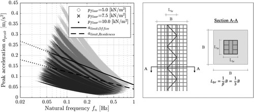
Buildings with a braced internal core as the sole lateral stiffening system do not satisfy the peak deformation criterion of H/500 nor the serviceability criterion in ISO 10137 (Citation2007). This is due to the lightness and flexibility of the structure. Furthermore, large tensile forces arise from the load-resisting mechanism. With a ratio between the internal and external tube β of 3, the serviceability limits are exceeded for buildings taller than 50 m. If the internal to external tube ratio β is 2, the limit is about 63 m. These must be anchored and may require uneconomical solutions. Compared with lateral stiffening systems with only a central core, the tube-in-tube systems with semi-rigid joints in the external tube and a braced internal tube can achieve two to three times the stiffness. shows that most of the heavier tube-in-tube systems with a dead load of 10 kN/m2 and various lighter configurations can satisfy the serviceability criterion in ISO 10137 (Citation2007).
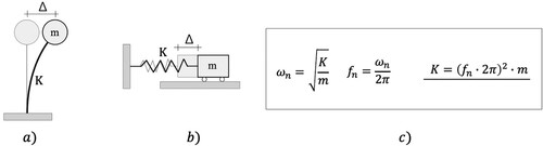
The buildings can be idealized as a single degree-of-freedom system with a mass m and stiffness K. Thus, the stiffness K refers to the global lateral stiffness of the building and the dynamic properties for different parameters can be compared through the global lateral stiffness K. This is illustrated in , where ωn is the natural angular frequency and fn is the natural frequency.
Figure 7. A single-degree-of-freedom system (a) is used to represent the building stiffness in the first mode. The equivalent spring-mass system (b) is denoted by the stiffness K (c).
A comparison between different parameters against the lateral building stiffness K is shown in , where the following parameters are varied: the elastic modulus of the material Emean, cross-sectional height of the columns hc, cross-sectional height of the beams hb and the bracing hbr, the stiffness ratio of the beam-column joint α, the width ratio between the internal and external tube β, and the width of the bay lb. To compare the different parameters, one parameter is varied while the rest remain fixed at a reference value, which is shown by the vertical dotted line.
Figure 8. Comparison of parameters with constant reference values. The reference values are: nc = 33, vb,0 = 25.0 m/s, pfloor = 7.5 kN/m2, δs = 0.05.
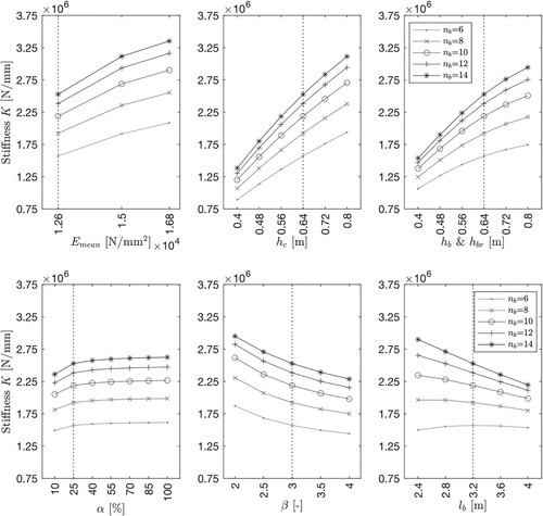
The geometry-related parameters have the greatest influence on the building stiffness. In the tube-in-tube systems, column and beam cross-sections seem to have a similarly strong influence on the stiffness K compared what Cao and Stamatopoulos (Citation2021a) found for systems with trusses in the façade, where the influence of the cross-sections is less important. Since the beam-column joint stiffness Krot is a ratio α of the beam stiffness, an increase in the cross-sections result in a subsequent increase of the joint stiffness Krot.
As the number of bays increases, the bay length becomes more important. With a small number of bays between six and eight, the influence is small for bay lengths between 2.4 and 4.0 m. This may be due to the balance between the stiffness contribution from the beams and the stiffness contribution from the geometry of the building. The stiffness contribution from geometry comes from the building’s second moment of area. Consequently, an increase of the overall stiffness is provided when more bays are included since the second moment of area is increased, while the longer bay lengths lead to a structural stiffness decrease due to slender and therefore softer beams. With six to eight bays, this balance is mostly stable and the influence of the bay length lb becomes more important from ten bays and more.
The beam-column joint stiffness Krot has a large impact on the stiffness of the buildings when the stiffness ratio α is between 0 and 0.1. For stiffness ratios α of more than 0.1, the impact is smaller due to the large number of beam-column joints. A stiffness ratio α of 0.10 in the beam-column joints results in a global lateral stiffness K of about 85% when compared with an equivalent building with rigid beam-column joints. If the stiffness ratio α is further increased to 0.20, the global lateral stiffness K is equivalent to 95% when compared with an equivalent building with rigid beam-column joints. A further increase of the stiffness ratio α does not result in large gains. Thus, the development of semi-rigid beam-column joints should target a stiffness ratio α between 0.10 and 0.20. However, such stiffness ratios result in stiffnesses, which are currently challenging to achieve for timber buildings in practice. Consider a building where the cross-sections of the beams and columns are 36×64 cm, bay length Lb is 4.0 m, floor height lc is 3.5 m, and the elastic modulus E is 12 600 N/mm2. Then, a stiffness ratio α of 10% results in a rotational stiffness Krot of 231 500 kNm/rad. Through experimental and analytical considerations Stamatopoulos et al. (Citation2022) showed that their current system based on threaded rods resulted in a rotational stiffness Krot in the order of 4000 kNm/rad per shear plane.
Similar to Cao and Stamatopoulos (Citation2021a, Citation2021b) and Vilguts et al. (Citation2021), the natural frequencies fn of the buildings deviate significantly from the expression in EN Citation1991-Citation1-Citation4 (Citation2010):
(5)
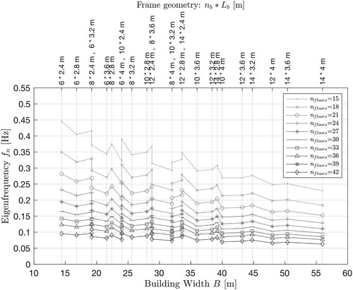
(5) For the tube-in-tube systems, the natural frequencies fn are lower than in EN Citation1991-Citation1-Citation4 (Citation2010). The natural frequency fn is less sensitive to changes in the building width B as the buildings become taller, this is shown in . shows the natural frequencies fn for tube-in-tube systems with a dead load pfloor of 7.5 kN/m2, beam-column joint stiffness α of 0.10, elastic modulus Emean of 12,600 N/mm2, shear modulus Gmean of 650 N/mm2, and member heights hc, hbr, and hc of 64 cm. The other parameters are similar to previous simulations.
Figure 9. Natural frequencies for different building heights and widths.
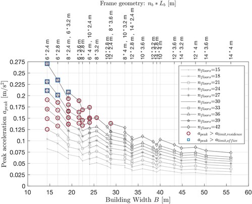
In , the peak accelerations are shown. The structural parameters are similar to the parameters in . The different curves represent the building heights showing the number of floors, and the colours indicate if the serviceability criterion from ISO 10137 (Citation2007) were not fulfilled for residential (red) or residential and office purposes (blue). The results indicate that the tube-in-tube system fulfilled the serviceability criterion from ISO 10137 (Citation2007) in the majority of the cases for the given parameters. Depending on the geometry, buildings with up to 42 storeys or 147 m are possible for building widths of more than 30 m based on the tube-in-tube systems. For smaller building widths of about 26 m, the limit is at around 36 storeys or 126 m.
Figure 10. Peak accelerations for different building heights and widths.
Conclusion
In the past decades, advancements in timber engineering has led to a rapid increase in the height of timber buildings. However, a system is often chosen where a reinforced concrete core provides the lateral stiffness. To decrease the carbon footprint of the buildings, construction time, and the wide gaps in tolerances between different materials, a lateral stiffening system based on a tube-in-tube system with timber components is presented here. Here, the internal tube consists of a braced timber frame and the external tube consists of a regular frame with semi-rigid beam-column joints. To assess the lateral stiffening system, the wind-induced serviceability of timber buildings between 50 and 147 m tall are assessed for more than 500 000 systems through a finite element framework. The wind loading is in accordance with EN 1991-1-4 and the serviceability is assessed following ISO 10137.
The simulations revealed that tube-in-tube systems for tall timber buildings are feasible for building heights of up to 147 m from a serviceability perspective. Such heights can be achieved by beam-column joint stiffnesses between 0.10 and 0.20 of the flexural beam stiffness. The lateral stiffening system is most sensitive to geometrical parameters such as the number of bays and their length, where more bays with shorter bay lengths are beneficial. For pinned beam-column joints in the external tube, a building height of about 50 m can be achieved.
Here, the simulations are based on a conservative logarithmic decrement of 0.05. It is likely that the damping in such buildings is higher. However, the exact quantity of damping can only be found via measurements on such buildings. The importance of the logarithmic decrement is particularly important in areas where the seismic design becomes the governing design criterion. Thus, the results can be interpreted as a worst-case scenario. The results show that an architecturally flexible building without bracings in the façade is possible for tall timber buildings via a tube-in-tube system with joint stiffnesses between 0.10 and 0.20 and uniform mass distributions along the height.
Acknowledgments
This article has been written within the framework of the project “lateral stiffening systems for tall timber buildings”. The authors gratefully acknowledge the funding from Innosuisse – Swiss Innovation Agency. Special thanks also go to the project partners Boltshauser Architekten AG, Schnetzer Puskas Ingenieure AG, and Swiss Life AG for their support.
Disclosure statement
No potential conflict of interest was reported by the author(s).
References
- Abrahamsen, R. (2018) Mjøstårnet - 18 storey timber building completed. 24. Internationales Holzbau-Forum IHF.
- Ali, M. M. and Moon, K. S. (2007) Structural developments in tall buildings: current trends and future prospects. Architectural Science Review, 50(3), 205–223.
- American Society of Civil Engineers (2022) ASCE standard ASCE/SEI 7-22: Minimum Design Loads and Associated Criteria for Buildings and Other Structures (ASCE/SEI 7-22), available at: https://ascelibrary.org/doi/epdf/10.1061/9780784415788.
- Bainbridge, R. J. and Mettem, J. C. (1998) A review of moment-resistant structural timber connections. Proceedings of the Institution of Civil Engineers - Structures and Buildings, 128(4), 323–331.
- Cao, A. S. and Stamatopoulos, H. (2021a) A theoretical study of the dynamic response of planar timber frames with semi-rigid moment-resisting connections subjected to wind loads. Engineering Structures, 240. https://doi.org/10.1016/j.engstruct.2021.112367
- Cao, A. S. and Stamatopoulos, H. (2021b) Theoretical studies of tall timber buildings subjected to service-level wind loads. Conference proceedings of WCTE2021.
- EN 1991-1-4 (2010) Eurocode 1: Actions on structures - Part 1-4: General actions -Wind actions. European Committee for Standardization.
- ISO 10137 (2007) Bases for Design of Structures – Serviceability of Buildings and Walkways Against Vibrations. International Organization for Standardization.
- Johansson, M., Linderholt, A., Bolmsvik, Å, Jarnerö, K., Olsson, J. and Reynolds, T. (2015) Building higher with light-weight timber structures – the effect of wind induced vibrations. Proceedings of the Internoise 2015 Conference.
- Johansson, M., Linderholt, A., Jarnerö, K. and Landel, P. (2016) Tall timber buildings – A preliminary study of wind-induced vibrations of a 22-storey building. Proceedings of the World Conference on Timber Engineering (WCTE 2016).
- Lippert, P. (2002) Rahmenecken aus Holz mit eingeklebten Gewindestangen. PhD thesis, Institut für Konstruktion und Entwurf, Universität Stuttgart.
- Lui, E. M. and Lopes, A. (1997) Dynamic analysis and response of semirigid frames. Engineering Structures, 19, 644–654.
- Rebouças, A. S., Mehdipour, Z., Branco, J. M. and Lourenço, P. B. (2022) Ductile moment-resisting timber connections: A review. Buildings, 12, 240.
- Reynolds, T., Chang, W. and Harris, R. (2011) Wind-induced vibration of tall timber buildings. IASS Annual Symposium: IABSE-IASS 2011.
- Schmid, V., Nettekoven, T. and Sutter, M. (2018) Hochhäuser in Holzbauweise – Konstruktionsprinzipien, dynamisches Verhalten, Verbundbau. 24. Interntionales Holzbau-Forum IHF 2018.
- Stamatopoulos, H., Malo, K. A. and Vilguts, A. (2022) Moment-resisting beam-to-column timber connections with inclined threaded rods: structural concept and analysis by use of the component method. Structural Engineering, 322. https://doi.org/10.1016/j.conbuildmat.2022.126481
- Tamboli, A. R. (2014) Tall and Supertall Buildings – Planning and Design (New York: McGraw-Hill Education).
- Torem, E. and Safarik, D. (2020) Timber Rising – Global Perspectives on Mass Timber Advances for the Tall Building Industry. Council on Tall Buildings and Urban Habitat.
- Vilguts, A., Nesheim, SØ, Stamatopoulos, H. and Malo, K. A. (2021) Parametric analyses and feasibility study of moment-resisting timber frames under service load. Engineering Structures, 228. https://doi.org/10.1016/j.engstruct.2020.111583
- Woschitz, R. and Zotter, J. (2017) Holzhochhaus Hoho Wien – Das Tragwerkskonzept. Österreichische Ingenieur- und Architekten-Zeitschrift, 162, 1–12.