
 ?Mathematical formulae have been encoded as MathML and are displayed in this HTML version using MathJax in order to improve their display. Uncheck the box to turn MathJax off. This feature requires Javascript. Click on a formula to zoom.
ABSTRACT
In this paper, the well-known elastic theory of layered beams (ETLB) is employed for the structural analysis of steel-timber composite (STC) floors, where the cross-laminated timber (CLT) slabs are located on top of a steel beam and assuming the linear elastic behaviour of the STC structure. In the analysis, the CLT slab is homogenized, i.e. the lamellas are replaced by a uniform fictitious material such that the resulting slab has equivalent selected structural properties to the original. Two homogenization methods are presented and compared for selected cases. The first method (EI-equivalent) is based on the bending stiffness of the CLT cross-section, where the shear factor is obtained by the Gamma method. The second method (EA-equivalent) enforces equal axial stiffness for the homogenized slab. The two methods are compared against full-scale test results available in the literature, including static four-point bending tests, and dynamic test cases. The goal is to explore the usability of the ETLB for STC structures and examines which of the two homogenization methods provides more accurate results. Based on the evaluation of the experiments, it can be concluded that the ETLB yields an accurate analytical approach for STC structures, and both methods provide accurate results.
Introduction
A composite structure is a union of two or more parts of different materials acting together for improved structural performance, for example, reduced weight, better material efficiency, increased load-bearing capacity, and the cost of the structure. Recent studies have also addressed new attributes such as dismantling and environmental impact of steel-timber composite (STC) floors (Falk Citation2013, Loss et al. Citation2015, Citation2016a, Citation2016b, Kyvelou et al. Citation2021) which have gained more attention due to the global efforts to reduce greenhouse emissions and preserve natural resources. However, the current design rules for mechanically joined timber beams presented in the standard EN 1995-1-1 (CEN Citation2005b) do not provide guidelines for the design of composite beams. Details for the design of steel-concrete composite beams are presented in Eurocode EN 1994-1-1 (CEN Citation2005a), but these rules are not directly applicable to steel-timber composite beams due to the different mechanical behavior of concrete and timber. Concrete can be designed using the theory of plasticity, which is not suitable for timber in general. The lack of design rules and standards for steel-timber and especially for steel-CLT composite beams keeps the technological development pace low, hindering the practical implementation of these structures.
A growing number of studies address the lack of design rulers by showing the benefits of STC structures, experimenting with different structural configurations, testing various connection types between steel and timber, and creating new analytical and FEM-based calculation procedures based on experiments. The overall benefits of steel-timber composite floors are discussed in (Loss et al. Citation2015, Citation2016a, Citation2016b, Falk Citation2013, Heinisuo et al. Citation2019). Based on these studies, the greatest benefits of steel-timber composite floors are quick installation on-site, dismantling capability, and high load-bearing capacity compared to the non-composite situation which reduces greenhouse emissions.
Numerous experiments have been carried out on steel-timber composite floors testing the load-bearing capacity of different structural configurations in order to understand the mechanics of the steel-timber interface (Hassanieh et al. Citation2016b, Citation2017a, Citation2017b, Citation2019, Masoudnia et al. Citation2018, Kyvelou et al. Citation2021). The outcome of these studies shows that in steel-timber composite structures, whether with laminated veneer lumber (LVL) or CLT, the load-bearing capacity is significantly improved due to the composite action. Moreover, experiments regarding various joints between steel and timber to facilitate the composite action have been intensively studied by (Asiz and Smith Citation2011, Hassanieh et al. Citation2016a, Citation2016c, Chybinski and Polus Citation2019, Citation2021, Citation2022, Yang et al. Citation2020). These studies have presented analytical approaches for determining the strength and stiffness of different steel-timber shear connections.
Based on the presented experimental studies, analytical calculation methods and FEM-models have been developed to capture the behavior of different STC floor configurations (Loss and Davison Citation2017, Roncari et al. Citation2021, Yang et al. Citation2021, Chybinski and Polus Citation2021, Karki et al. Citation2021). The findings of Loss and Davison (Citation2017) show that steel-CLT composite structures can be analyzed by the theory of linear elasticity for the whole structure and thus the use of the gamma method by Möhler (Citation1956) can be applied. However, recent studies by Kyvelou et al. (Citation2017), (Citation2021) show that the plasticity approach presented in Eurocode EN 1994-1-1 (CEN Citation2005a) can be applied to a composite structure consisting of a cold-formed steel profile and oriented strand board (OSB) on top of the steel beam. Moreover, Karki and Far (Citation2021) are discussing in detail the benefits, challenges and recent studies of cold-formed STC structures.
The main questions regarding general analytical calculation methods for STC floors are (1) how to calculate the effective width of the slab (Masoudnia Citation2020), (2) how to replace the original inhomogeneous (layered) cross-section of CLT with a homogeneous material such that the resulting slab has equivalent selected structural properties with the original slab, i.e. how to homogenize the CLT slab, and (3) what methods to use for the analysis of steel-timber composite beams. For the first issue, Masoudnia et al. (Citation2018) examined the effective width through a series of experiments but they did not propose an analytical method for determining the effective width. Secondly, the CLT cross-section is homogenized in most studies by the Gamma-method, presented thoroughly in The CLT handbook (Gustafsson et al. Citation2019), or the Shear Analogy method (Gagnon and Pirvu Citation2011). However, the Gamma method is limited to a maximum of 5-layer CLT slab. Lastly, several researchers have discussed analytical methods to calculate the capacity of the steel-timber composite structures (Loss and Davison Citation2017, Masoudnia Citation2020, Kyvelou et al. Citation2017, Kyvelou et al. Citation2021, Heinisuo et al. Citation2019).
In this paper, the homogenization of the CLT cross-section is treated, and a general analytical method for STC structures is employed for the elastic analysis of steel-CLT composite beams, where the CLT is located on top of the steel beam. The analysis is conducted by using the well-known elastic theory of layered beams (ETLB), (Parland Citation1946, Rafik Citation1982). The ETLB was first considered for slim-floor steel-timber composite beams by (Heinisuo et al. Citation2019), and in the present study, the theory is further employed and analyzed for STC structures. Two methods for homogenization of the CLT cross-section are presented and compared. The first method (EI-equivalent) is based on the bending stiffness of the CLT cross-section, where the shear factor is obtained by the Gamma method. The second method (EA-equivalent) uses axial stiffness of the CLT cross-section. These two methods are validated against full-scale test results available in the literature, including four static four-point bending test cases (Hassanieh et al. Citation2017a, Citation2017b) and two dynamic test cases (Chiniforush et al. Citation2019). In the calculations, linear-elastic behavior is assumed for the entire composite beam (steel + connections + CLT). The main hypotheses are:
The elastic theory of layered beams can provide accurate results for the examined steel-CLT composite structures.
The EA-equivalent method provides more accurate results than EI-equivalent.
The paper is organized as follows. Firstly, homogenization of the CLT slab is presented. This is followed by fundamental principles of the elastic theory of layered beams. The theory is then applied to a beam in four-point bending and the obtained numerical results are compared with associated experimental test results. Finally, conclusions on the suitability of the proposed method for the analysis of steel-timber composite beams are discussed and further research topics are identified.
The proposed method for CLT cross-section homogenization
Because the CLT slab itself is a layered structure, the analysis of the steel-CLT composite beam becomes difficult since the examined structure has a layered beam inside a layered beam. To facilitate the analysis, the CLT slab is homogenized such that the CLT cross-section is replaced by a fictitious homogeneous material, so that the resulting cross-section and the original are equivalent with respect to selected structural properties, see . As a result of homogenization, a unique value for the elastic modulus, E, for the homogenized CLT slab is obtained. The dimensions of the CLT slab remain unchanged during homogenization.
Figure 1. (a) Original layered cross-section, (b) homogenized cross-section.
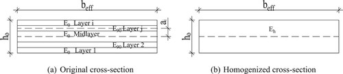
In this study, two homogenization approaches are considered for the CLT cross-section. First, the method presented e.g. in (Gustafsson et al. Citation2019) is used so that the bending stiffness EI of the original CLT cross-section and the homogenized cross-section are set equal. This method is called the EI-equivalent method. Secondly, a new method is proposed, called the EA-equivalent method, where the axial stiffness, EA, of the original and the homogenized cross-section are set equal. The subsequent analysis shows that the EA-equivalent method is simpler than the EI-equivalent method. In the EA-equivalent method, the elastic modulus of the homogenized CLT cross-section, , is obtained from the following equation
(1)
(1) where
is the axial stiffness of the original layered cross-section and
is the area of the homogenized cross-section according to . In (1)
is the effective width of the CLT slab that can be obtained from tests, see e.g. Hassanieh et al. (Citation2017b). The axial stiffness of the original, layered CLT cross-section
can be calculated straightforwardly layer-wise so that (1) implies
(2)
(2) where the elastic modulus,
, depends on the orientation of the layer, being
for layers that are parallel to the beam axis, and
for the transverse layers. All the layers can be utilized in (2), if the layers are edge-glued, see Gustafsson et al. (Citation2019). Otherwise only the layers parallel to the beam axis are considered.
Similarly, in the EI-equivalent method, the elastic modulus of the homogenized CLT cross-section, , is determined from the condition that the bending stiffnesses of the original layered cross-section and the homogenized cross-section are equal:
(3)
(3) where
is the second moment of area of the homogenized cross-section, and
refers to the original layered CLT cross-section. Using the Gamma-method, the bending stiffness of the layered cross-section can be stated as:
(4)
(4) where
is the elastic modulus for layer i,
is the second moment of area of layer i with respect to its local major axis, and
is the distance between the cross-section centroid and the centroid of layer
. The gamma factor,
, takes into account the stiffness of the different CLT layers. The gamma factor can be calculated for the CLT cross-section as presented in EN 1995-1-1 (CEN Citation2005b) (see also The CLT Handbook (Gustafsson et al. Citation2019)):
(5)
(5) where
is the span of the beam,
is the height of layer i,
is the height of the adjacent layer and
is the rolling shear stiffness of the adjacent layer.
Fundamentals of elastic layered beam theory
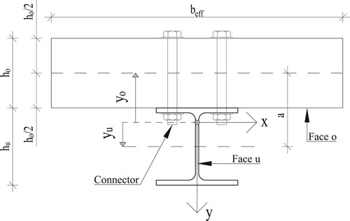
The elastic theory of layered beams has been widely used in the analysis of sandwich structures, but recently it has been adopted also for CLT structures by Heinisuo and Pajunen (Citation2021) and for slim-floor steel-timber composite beams by Heinisuo et al. (Citation2019). In the latter study, ETLB was adopted for a simply supported slim-floor composite beam. In the present paper, ETLB is employed for a thicker steel-timber composite floor with a more conventional shear connection configuration as depicted in . Using the classical notation of the method, the cross-section of the composite beam consists of two “faces”, where the steel and timber parts are denoted by “face u” and “face o”, respectively. The two faces are joined by the shear connection between the steel and timber, called the “core . The shear connection is assumed to be continuous along the beam axis.
Figure 2. Cross-section of the examined composite beam with homogenized CLT slab.
The governing differential equation for the beam deflection, v, is (Stamm and Witte Citation1974)
(6)
(6) where p(x) is the loading intensity along the beam, and the bending stiffness of the steel-timber composite cross-section, B, is formulated as the sum of the bending stiffness of the timber part
, bending stiffness of the steel part
and the Steiner term
, which represents the composite action. The bending stiffnesses can be expressed as
(7)
(7) where
is the elastic modulus for the homogenized CLT cross-section obtained by the EA- or EI-equivalent method according to Equations (2) or (4), respectively. Furthermore,
is the elastic modulus of steel, and
is the second moment of area of the steel part. Coordinates
and
are the distances of the centroids of the CLT cross-section and the steel part from the centroid of the composite beam, respectively, see . According to Stamm and Witte (Citation1974) and selected coordinate, see , the distances are
(8)
(8) where
is the distance between the centroids of the CLT and steel parts, see . It is worth noting that, in ETLB, the shear connection between different cross-section layers, steel and timber, is explicitly included in the governing differential equations as opposed, e.g. to the Gamma-method, where the effect of the shear connections is included in the bending stiffness of the layers. Following Stamm and Witte (Citation1974), the shear connection stiffness between the steel and CLT parts can be written as
(9)
(9) where
is the shear stiffness of one connector, and
is the distance between the connectors along the beam axis. In this study, the stiffness of the connector,
, is taken from the test results of Hassanieh et al. (Citation2017a) corresponding to the so called
value which denotes the initial slope of the load – slip curve.
In this study, ETLB is applied to the test set-up depicted in , where a longitudinal slip between the timber and steel can occur. The governing equations for displacements and stress resultants can be formulated according to Stamm and Witte (Citation1974).
Figure 3. Composite beam in four-point bending.
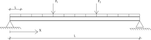
The total deflection, v(ξ), for the considered beam can be calculated as a sum of deflections due to two distinct loads and
. Using the notation
, the deflection due to load
acting at x = e can be written as
(10)
(10)
(11)
(11)
(12)
(12) where ϵ = e/L, and the subscripts 1 and 2 are valid for 0 ≤ ξ ≤ ϵ and ϵ ≤ ξ ≤ 1, respectively. Similarly, bending moments in the cross-section can be written as
(13)
(13)
(14)
(14)
(15)
(15)
(16)
(16) where the subscript i is ‘u’ for the steel part and ‘o’ for the CLT part. The
,
and
refer to the bending moments carried by the Steiner term (composite action), steel part and the timber part, respectively.
In the above Equations (10)–(16), the stiffness ratio α and the parameter λ are defined as
(17)
(17)
(18)
(18) where the parameter
.
Finally, the stresses in timber and steel, and
, respectively, can be calculated as:
(19a)
(19a)
(19b)
(19b) where
and
refers to the elastic modulus of the examined layer in the case of CLT cross-section and steel, respectively.
is the distances of the centroids of the steel part from the centroid of the STC beam. Likewise,
is the distance of the centroid of the examined CLT layer from the centroid of the STC beam. Lastly,
and
are the local coordinate of the examined steel part and CLT layer which can be calculated as
and
where the h refers to the height of the examined part or layer. All coordinate distances,
,
,
and
are obeying the local coordinate axis defined in .
Determination of key structural responses
In order to compare the analytical results according to the ETLB with the experimental results given in (Hassanieh et al. Citation2017b, Chiniforush et al. Citation2019), three key responses of the composite beam are calculated:
Total load value F* at the moment when yielding occurs in the steel beam
Deflection, v(1/2ξ), at the mid-span of the beam at the load level F*
The lowest natural frequency,
These responses were chosen because they are reported in the referred literature.
From the static model shown in , it can be seen that the steel beam reaches the yield stress, , at the bottom of the cross-section and in the midspan of the composite beam. The yield stress,
, can be written as
(20)
(20) where
and
denote the bending stresses due to forces
and
, respectively. Due to symmetry of the loading,
, the yield stress can be stated as
(21)
(21)
The tensile bending stress, can be obtained from Equation (19b) by substituting Ei = Eu, yi = hu/2 and the expressions of Bs, yu and yo from Equations (7) and (8), respectively. This leads to the following expression:
(22)
(22) where
is the bending stress in steel due to the bending moment
carried by the steel part,
is the bending stress in the steel due to the bending moment
carried by the Steiner term (composite action), and
is the elastic section modulus of the steel beam, a () is the distance between centroid lines of steel and CLT cross-sections, and
is the cross-sectional area of the steel part.
Using Equations (14) and (16), the axial stress due to bending, , can be written as
(23)
(23)
Substituting Equation (23) into Equation (21), gives the load F* corresponding to first yielding in the steel part as:
(24)
(24)
The lowest natural frequency for the steel-timber composite beam following Stamm and Witte (Citation1974) is:
(25)
(25) where
is the beam weight per unit length.
Reference cases for numerical validation
The proposed analytical methods, EA- and EI-equivalent, are validated against six test cases on simply supported steel-timber composite beams reported by (Hassanieh et al. Citation2017a, Citation2017b, Chiniforush et al. Citation2019). Total of four statically and two dynamically loaded beams are considered and the configuration of the STC beam is depicted in . In all cases, the outer layers of the CLT slab are parallel to axis of the steel beam and L = 5850 mm (in dynamic cases, L = 5800 mm). The only exception is case 4, in which the outer layers of the CLT slab are perpendicular (rotated 90 degrees) to the steel beam and L = 3850 mm. The width of the 5-layer CLT timber part is 800 mm for the static cases and 1000 mm for the dynamic cases. Essential parameters of the tested beams are presented in . Note, that all the data presented in is taken from studies conducted by Hassanieh et al. (Citation2017a), (Citation2017b), except the rolling shear stiffness , for which no value was given, and the value from The CLT-handbook (Gustafsson et al. Citation2019) was used instead. In all calculations, the effective width,
, equals the actual width of the CLT slab presented in and .
Figure 4. Schematic of the static reference cases.
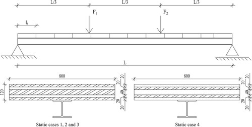
Table 1. Parameters of the static analyses.
Table 2. Parameters used in vibration analyses.
The dynamical test cases are taken from Chiniforush et al. (Citation2019). The measured lowest natural frequency values are compared to the results obtained by the analytical method. The test setup resembles the static test cases 1–3, presented in . Parameters of the test setup are presented in .
Results
The main results of the static cases are collected in , where the yield load, calculated by Equation (24), and the corresponding midspan deflection, calculated by Equation (12), are reported. Both responses have been calculated by the EI-equivalent and EA-equivalent homogenization methods. Comparing the calculated yield load with the measured values, it can be observed that the yield load is underestimated in cases 1, 3 and 4 and overestimated in case 2. In general, the ETLB is able to predict the yield load well, providing results within 10% of the Test values (see ). For the mid-span deflection v(1/2ξ), it can be seen that the calculated values are greater than the Test values in all cases, being nearly equal in case 4. It is interesting to note that the deviation of the calculated deflection from the Test value increases with decreasing shear connection stiffness: the largest stiffness is in case 1, followed be case 3 and case 2 (see ). Overall, it can be concluded that both homogenization methods can predict the yield load and the midspan deflection fairly accurately.
Table 3. Comparison of selected key responses in the static analysis cases 1-4, where EA and EI refer to the proposed CLT homogenization methods and Test to the obtained values from studies.
The lowest natural frequencies obtained for the dynamic cases are given in . Also in the dynamic cases, the theoretical results match the tested values rather well. From and it can be seen that EA- and EI-equivalent methods provide virtually identical results with respect to all responses. For practical purposes, because the calculated key responses match the corresponding test values so well, it can be concluded that the ETLB with both EA- and EI-equivalent methods captures the structural behavior of the composite beam with sufficient accuracy, and the analytical methods can be considered validated. Consequently, the hypothesis 1 of this paper (see Introduction) is valid.
Table 4. Comparison of the measured and calculated lowest natural frequency values in the dynamic analysis cases 5–6 were EA and EI refer to the proposed CLT homogenization methods and Test to the obtained values from studies.
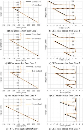
The piecewise linear axial stress distribution over the STC cross-section and CLT cross-section are calculated by using the equations (19a) and (19b), see . For case 1, the STC cross-section is shown in (a), with a detailed presentation of stresses in CLT layers in (b). The stress at the bottom of the steel part reaches the yield strength whereas the stresses in CLT are well below the allowable compression value ( given by Hassanieh et al. (Citation2017b)). Also, it can be seen that stiffer the connection between the steel and CLT the bigger the stress transfer to the CLT part. This is especially true when looking at cases 1 and 3 because the only thing they had different was the connection stiffness. Overall, both EA- and EI-equivalent methods are providing virtually identical results when examining the steel part and in CLT, the EA-equivalent is providing a little bit higher stress values. The exception being the case 4 where the CLT layers were rotated 90 degrees, in relation to the cases 1–3, where the EA-equivalent is giving smaller values. It should be noted that case 4 had also the biggest difference (21 kN) when considering the total yield load F*, see .
Figure 5. Bending stress distribution in the STC cross-section in the analysis case 1 at the mid-span with the load level F*.
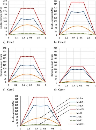
displays the distribution of bending moment between steel, CLT and composite action along the beam axis for cases 1–4. When examining case 1, the maximum total bending moments are and
, of which the steel part carries
(57,8%) and
(57,3%), and CLT part carries
(4,4%) and
(4,6%). The remainder is carried by the composite action
(37,7%) and
(38,0%). Composite action is rather significant in case 1, which illustrates the benefit of combining the CLT and the steel parts into a composite structure. However, the connection stiffness is affecting greatly on how significant the composite action,
, is. This can be seen particularly clear by comparing cases 1 and 3 because the only change between these test setups where the stiffness of the connection. From it can be seen that case 1 with the stiffer connectors can carry a larger portion of the total moment on composite action (Ms) than case 3. Case 1 has a 29,5% stiffer connection than case 3 and likewise, the composite action (Ms) is 24,5% (EI) and 24,2% (EA) larger.
Figure 6. Bending moment distribution for different cross-sections in analysis case 1–4 with load level F*. The subscripts u, o, and s denote the steel part, timber part and the Steiner term, respectively. Subscripts EA and EI refer to the CLT homogenization method.
Through the calculation process, the CLT cross-section was homogenized by using two different approaches, EA- and EI-equivalent methods. The elastic moduli for the homogenized CLT cross-sections are shown in . Also, here both methods are providing similar results except in case 4 (with CLT lamellas rotated 90 degrees from the configuration in cases 1–3), where the EA-equivalent yields 35% greater value of the elastic modulus for the homogenized CLT cross-section. Nevertheless, also in case 4, the EA- and EI-equivalent methods provide nearly identical results (see ). This can be explained by the fact that the portion of the CLT slab of the total bending moment, , and composite action,
, are very small, as can be seen in (d). It should be noted that cases 1–3 and cases 5–6 have different
value because the effective width,
, was different, see and , and this is one of the parameters when homogenization is conducted by the gamma method, see Equation.
Table 5. The elastic modulus for the homogenized CLT cross-section was obtained by the presented EA- and EI-equivalent methods.
Based on , and it is straightforward to conclude, that the EA-equivalent method can be used in the CLT homogenization for such composite beams in which the steel part is relatively stiff when compared to the timber part. Additionally, in composite beams with a more dominant CLT-part, the timber part would carry a larger portion of the bending moment making the differences between EA- and EI-methods more visible in the structural analysis results. Also, it seems, based on the static cases 1–4, that ETLB and both EA- and EI-equivalent methods are providing more accurate results, regarding the yield load F*, when the STC beam is using a stiffer connection.
Conclusion
This study explored the use of classical elastic theory of layered beams (ETLB) for the structural analysis of steel-timber composite (STC) beams in the linear elastic range. Additionally, to simplify the computational aspects of the layered CLT cross-section, two homogenization methods called EA-equivalent and EI-equivalent methods were presented and numerically verified. The presented theory was verified against test results found in the literature. These included four static and two vibrations test cases. According to the obtained results, the ETLB is valid for the structural analysis of STC beams as expected due to the sound basis of the theory, and the accuracy of the analytical method is very promising. However, it must be noted, that the number of adopted reference cases was limited, and the data contained discrete test values and no large test-series results were available. Hence, the accuracy of both the ETLB theory and the applied homogenization methods, EA- and EI-equivalent, should be considered as further research topics. Based on the findings in this paper, the computational advantages of the presented EA-equivalent method seem to be promising. For future studies, the authors suggest full-scale test series where the connection stiffens and the height of the CLT are varied. Especially CLT that has more than five layers would be interesting to analyse using the EA-equivalent method. It would also be very good to have at least two identical test setups so that the natural variation in timber could be seen. This would help to formulate and validate a unified analytical method for steel-timber composite beams.
Disclosure statement
No potential conflict of interest was reported by the author(s).
References
- Asiz, A. and Smith, I. (2011) Connection system of massive timber elements used in horizontal slabs of Hybrid tall buildings. Journal of Structural Engineering, 137(11), 1390–1393.
- CEN (2005a) Eurocode 4: Design of composite steel and concrete structures - Part 1-1: General rules and rules for buildings. EN 1994-1-1.
- CEN (2005b) Eurocode 5. Design of timber structures - Part 1-1: General. Common rules and rules for buildings. EN-1995-1-1.
- Chiniforush, A. A., Alamdari, M. M., Dackermann, U., Valipour, H. R. and Akbarnezhad, A. (2019) Vibration behaviour of steel-timber composite floors, part (1): experimental & numerical investigation. Journal of Constructional Steel Research, 161, 244–257.
- Chybinski, M. and Polus, L. (2019) Theoretical, experimental and numerical study of aluminium-timber composite beams with screwed connections. Construction and Building Materials, 226, 317–330.
- Chybinski, M. and Polus, L. (2021) Experimental and numerical investigations of aluminium-timber composite beams with bolted connections. Structures, 34, 1942–1960.
- Chybinski, M. and Polus, L. (2022) Mechanical behaviour of aluminium-timber composite connections with screws and toothed plates. Materials, 15, 1.
- Falk, A. (2013) Timber-Based Material Hybrid Systems for Improved Environmental Performance. Proceedings of the International Association for Shell and Spatial Structures (IASS) Symposium 2013. 23-27 September, Wroclaw University of Technology, Poland.
- Gagnon, S. and Pirvu, C. (2011) CLT Handbook: Cross-Laminated Timber (Québec: FPInnovations).
- Gustafsson, A., Crocetti, R., Landel, P., Olsson, J. r., Pousette, A. and Östman, B. (2019) The CLT Handbook (Swedish Wood: Föreningen Sveriges Skogsindustrier).
- Hassanieh, A., Chiniforush, A. A., Valipour, H. R. and Bradford, M. A. (2019) Vibration behaviour of steel-timber composite floors, part (2): evaluation of human-induced vibrations. Journal of Constructional Steel Research, 158, 156–170.
- Hassanieh, A., Valipour, H. R. and Bradford, M. A. (2016a) Experimental and analytical behaviour of steel-timber composite connections. Construction and Building Materials, 118, 63–75.
- Hassanieh, A., Valipour, H. R. and Bradford, M. A. (2016b) Experimental and numerical study of steel-timber composite (STC) beams. Journal of Constructional Steel Research, 122, 367–378.
- Hassanieh, A., Valipour, H. R. and Bradford, M. A. (2016c) Load-slip behaviour of steel-cross laminated timber (CLT) composite connections. Journal of Constructional Steel Research, 122, 110–121.
- Hassanieh, A., Valipour, H. R. and Bradford, M. A. (2017a) Composite connections between CLT slab and steel beam: experiments and empirical models. Journal of Constructional Steel Research, 138, 823–836.
- Hassanieh, A., Valipour, H. R. and Bradford, M. A. (2017b) Experimental and numerical investigation of short-term behaviour of CLT-steel composite beams. Engineering Structures, 144, 43–57.
- Heinisuo, M., Mela, K., Pajunen, S. and Malaska, M. (2019) New steel-composite beam, Nordic system. XII Conference on Steel and Composite Construction. Coimbra, Portugal: ce/papers, 193-202.
- Heinisuo, M. and Pajunen, S. (2021) CLT beam analysis using classical elastic theory of layered beams. Rakenteiden Mekaniikka (Journal of Structural Mechanics), 54(4), 143–171.
- Karki, D. and Far, H. (2021) State of the art on composite cold-formed steel flooring systems. Steel Construction-Design and Research, 14(2), 117–127.
- Karki, D., Far, H. and Saleh, A. (2021) Numerical studies into factors affecting structural behaviour of composite cold-formed steel and timber flooring systems. Journal of Building Engineering, 44.
- Kyvelou, P., Gardner, L. and Nethercot, D. A. (2017) Design of composite cold-formed steel flooring systems. Structures, 12, 242–252.
- Kyvelou, P., Reynolds, T. P. S., Beckett, C. T. S. and Huang, Y. E. (2021) Experimental investigation on composite panels of cold-formed steel and timber. Engineering Structures, 247.
- Loss, C. and Davison, B. (2017) Innovative composite steel-timber floors with prefabricated modular components. Engineering Structures, 132, 695–713.
- Loss, C., Piazza, M. and Zandonini, R. (2015) Innovative construction system for sustainable buildings. Structural Engineering: Providing Solutions to Global Challenges. Geneva, Switzerland.
- Loss, C., Piazza, M. and Zandonini, R. (2016a) Connections for steel-timber hybrid prefabricated buildings. part I: Experimental tests. Construction and Building Materials, 122, 781–795.
- Loss, C., Piazza, M. and Zandonini, R. (2016b) Connections for steel-timber hybrid prefabricated buildings. part II: Innovative modular structures. Construction and Building Materials, 122, 796–808.
- Masoudnia, R. (2020) State of the art of the effective flange width for composite T-beams. Construction and Building Materials, 244.
- Masoudnia, R., Hashemi, A. and Quenneville, P. (2018) Predicting the effective flange width of a CLT slab in timber composite beams. Journal of Structural Engineering, 144, 7.
- Möhler, K. (1956) Über das Tragverhalten von Biegeträgern und Druckstäben mit Zusammengesetzten Querschnitten und Nachgiebigen Verbindungsmitteln (Germany: Technische Universität Karlsruhe).
- Parland, H. (1946) Yhdistettyjen puukannattajien lujuus (Strength of composite wooden structures). Helsinki.
- Rafik, Y. I. (1982) Influence of sheathing gaps on wood floor systems. Wood And Fiber Science, 15(3), 190–202.
- Roncari, A., Gobbi, F. and Loss, C. (2021) Nonlinear static seismic response of a Building equipped with Hybrid cross-laminated timber floor diaphragms and concentric X-braced steel frames. BuildingS, 11(1).
- Stamm, K. and Witte, H. (1974) Sandwichkonstruktionen (Wien: Springer).
- Yang, R., Li, H. T., Lorenzo, R., Ashraf, M., Sun, Y. F. and Yuan, Q. (2020) Mechanical behaviour of steel timber composite shear connections. Construction and Building Materials, 258.
- Yang, R., Wan, J., Zhang, X. and Sun, Y. (2021) Modelling of steel-timber composite beams: validation of finite element model and parametric study. Wood Research, 66(5), 806–820.