
ABSTRACT
Laminated veneer products (LVPs) are veneers glued together into a predetermined shape. Experimental and numerical investigations were performed under lamination and simultaneously bending of veneer laminate to study the stress distribution in the laminate. Laminates of different thicknesses were made of peeled veneers of European beech. The veneers were coated with adhesive, inserted in a mould which had the shape of a semicircle, and finally pressed at 20°C to a laminate. Two Teflon-polymer films including sensors for measurement of the contact pressure were placed on both sides of the laminate to measure the local contact pressure (contact stress) between the laminate and the mould. At the beginning of the bending process, the contact stresses were locally distributed over the laminate in a similar pattern as in a three-point bending; after the laminate was further bent, the stress distribution rearranged to be as in four-point bending. In the end of the moulding, the local contact stresses increased over the entire laminate and reached a ‘peak-value’ over bent area in the middle part of the mould. A finite-element model was created to study the bending process. Regarding the overall development of the contact stress variations, the experimental and the numerical results agreed.
Introduction
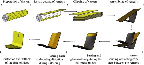
Laminated veneer products (LVPs) are produced by forming and gluing the veneers simultaneously against a mould to achieve a predetermined shaped LVP for which relative movements between veneers are rendered virtually impossible (Blomqvist Citation2016). This method is commonly used for the manufacture of complex forms for the use in furniture and interior items. The mould is in most cases of the male and female type, but for making a prototype or a partial component, it is possible to use only the male part of the mould and to apply the pressing forces through a vacuum bag process. The temperature during pressing is generally, but not necessarily, elevated to shorten the time for curing the adhesive and to a minor degree to soften the veneers. shows the principles of the manufacture of laminated products and some distortions that can occur in the product after pressing. An elastic spring-back always occurs when the product is unloaded after pressing and is taken into account when making the mould. Distortion may also occur in the final product a long time of use, especially when the product is subjected to moisture-content variations. Distortion is in general very troublesome in the production of LVPs.
Figure 1. Manufacture of laminated veneer products (LVPs) and distortions of the product after pressing (Ormarsson and Sandberg Citation2007).
A common problem in the manufacture of LVPs in complex forms is significant local compression stresses that may occur in the outermost veneers or in the entire laminate, resulting in inter-locking of veneer followed by veneer failure and/or residual stresses in the final LVP causing distortion (Blomqvist et al. Citation2013, Citation2014, Citation2019). This phenomenon is closely related to the design of the mould, but also the adhesive and veneer properties are important (cf. Hänsel et al. Citation2022).
The design of the mould is a complex process requiring technical skill to optimise the form of the mould to reach the desired form of the LVP without any damage. The knowledge of the moulding process and how a mould should be designed is deficient, and often linked to individuals with a long professional experience.
The formability of LVPs is highly dependent on the anatomical structure, the moisture content and temperature of the veneers. The transition temperature (Tg) of an amorphous polymer as wood is, marks the border between two fundamentally different states: the glassy, hard and brittle state and the soft, rubbery state (Van de Velde and Kiekens Citation2002), and is important to exceed for the plasticisation of the veneer. A veneer used in the manufacture of a LVP has a moisture content normally of about 6–10% which requires a temperature of about 180°C to fully plasticise the veneer (Navi and Sandberg Citation2012). In practice, it is enough to plasticise only the lignin to sufficient soften the veneer and facilitate the moulding; then a temperature of about 110°C is enough (Navi and Sandberg Citation2012).
The purpose of this study was to increase the knowledge of the moulding process for LVPs by studying the contact-stress distribution in the veneer laminate under moulding at 20°C. The experimental results were supplemented with finite-element analyses of the moulding process.
Materials and methods
Experimental method
Peeled veneers of beech (Fagus sylvatica L.) with a dimension of 340 × 140 × T mm were used for this study. The veneers were conditioned at 20°C and 20% relative humidity (RH) to approx. 4.5% equilibrium moisture content (EMC). The thickness of the veneers was made uniform by sanding. Only in-plane straight-grained veneers were used. The veneers were oriented cross-wise in the laminate (). The loose sides of the veneers were all oriented in a downward-facing direction, i.e. to the convex surface in the bent laminate. A urea-formaldehyde adhesive, without hardener, was spread between the veneers (175 g/(m2 bond-line)). The veneers were assembled so that the total thickness (Ttot) of the laminate was either 4.5, 4.9 or 5.5 mm ().
Table 1. Thickness, placement and orientation of veneer number i (Vi) in the laminate.
The bending was accomplished at a temperature of about 20°C. To ensure a stiff and stable press-tool (mould), the mould was made of steel plates with a thickness of 150 mm. shows the configuration of the mould, including the positioning of the veneers and ‘shims’.
Figure 2. Configuration of the mould with inlaid shims and veneers (V1–V5) in a deformed state. F = vertical pressing force. Shim means a Teflon-polymer film including sensors for measurement the local pressure. Measures in mm and degrees.
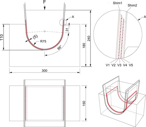
The veneers were inserted between the male and female parts of the mould and so-called shims, i.e. a Teflon-polymer film including sensors for measurement the local pressure (Tekscan Citation2020), were placed on each side of the laminate. In the length (bending) direction, the sensor measurements were recorded every 9.3 mm and in the width direction every 4.7 mm. The pressing force and the local contact pressure were recorded during the whole bending operation.
During bending operation, the mould was displacement-controlled at 11 positions (ui) and thereafter force-controlled at 10 positions (Fi) (). All measurements were recorded during short breaks between each position or force control state.
Table 2. Press-tool displacements (ui) and forces (Fi) where the local contact pressure were recorded.
FE simulation
Stress-and-deformation behaviours were analysed during bending process with a three-dimensional (3D) finite-element model developed for this project.
A sheet-forming simulation of the highly curved semicircle was performed with the FE-software ABAQUS/Standard (Dassault Systèmes Citation2020) using 3D static analysis for large deformations with full contact interaction between the three different components (i.e. the two-part mould, of which the upper part was movable and the lower part was fixed, and deformed veneers) used to simulate the veneer semicircle formation. The veneer of beech was cross-wise orientated in the mould, as in the experimental method. The semicircle consisted of five veneers with dimensions of 300 × 150 × 1.0 mm. The veneers were modelled as orthotropic material with stiffness parameters based on data presented by Kollmann and Côté (Citation1968), as shown in .
Table 3. The elastic material constants for beech used in the study.
The surface contact interactions between the veneers and between the mould of two parts are based on a penalty formulation for mechanical (i.e. normal) contact, which significantly reduces the contact forces because the surfaces are allowed to penetrate slightly into each other in this formulation. The interactional properties for this normal contact allow the surfaces to be separated again after contact. To simulate large bending deformation of the veneers, the model can simulate large sliding between the contact surfaces. The tangential contact interaction used in the model was calculated according to formulation of an isotropic finite friction with a friction coefficient of 0.2. shows the large bending-and-sliding deformations that developed during the moulding process.
Figure 3. Simulation of veneer forming using theory of large deformation and penalty contact formulation with finite sliding for contact surfaces.
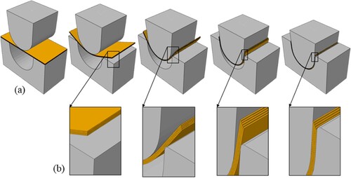
The close-up images shown in (b) illustrate the relative sliding between the veneers, and the other (a) depicts the large bending deformations and the significant sliding that occurs between the fixed part of the mould and the bottom veneer. This sliding displacement mainly occurred at the curved internal corner of the press-tool where the veneers were in local mechanical contact with the mould.
Results
Moulding a flat laminate into a highly curved laminate is a process wherein a small stack of veneers is gradually bent through a series of progressive mechanical contacts between the laminate and the press-tools (the mould) until the full curved shape of the product is reached. The outer veneers will get into significant local contact with the press-tool, and they must slide considerable along the surfaces of the press-tool. For highly curved products, contact stresses that are perpendicular to the grain may be very high, and cause local damage; local inter-locking can prevent the veneers to slide between each other and/or between veneer and the mould, which may cause significant in-plane tensile stresses in these areas.
The finite-element (FE) model was used to study the mechanical behaviour of the veneer and analyse the development of stresses throughout the moulding.
Experiment results
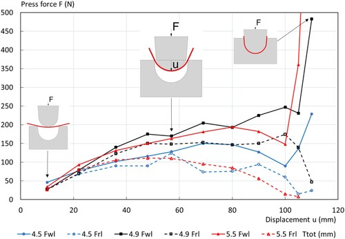
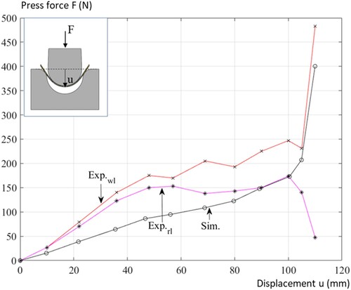
As was previously stated, the moulding tests were position-controlled at the 11 different vertical displacements (ui) delineated in . For different product thicknesses, shows the measured relationships between these prescribed press-tool positions and the total press force F. The work-load press force (Fwl) is defined as the instantaneous force that is necessary to reach a certain position in the tool, and the rest-load press force (Frl) is needed to maintain the given press-tool position after few minutes; in this way, the veneers are continuously pressed down with short brakes between the displacement steps. Note that the Frl curves are influenced by such factors as time, deformation rate, friction properties and the stiffness of the mould. The influence of these factors on the pressing forces will not be discussed in this paper.
Figure 4. Relations between press-tool displacements ui and measured forces at Fwl and Frl for three different thicknesses Ttot. Note the final Fwl = 1120 N for Ttot = 5.5 mm, which is outside the diagram range.
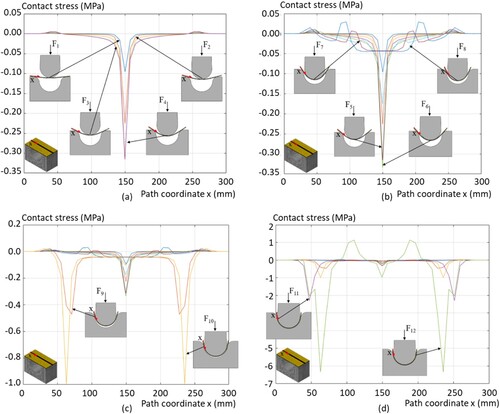
To study variation in contact stress between the press-tools and the outer veneers, special matrix-based sensor shims were used to measure the contact forces over the entire veneer surface, as already mentioned. Contact stress was then calculated as an average stress over the width of the veneers. (a–f) illustrates variations in the contact stress along the veneer length (i.e. path coordinate-x) at different displacement states of the press-tool. Note the different scales of the y-axes in the sub-figures.
Figure 5. Variation in contact stress along the path coordinate x. (a) u = 10 mm and Ttot = 4.9 mm; (b) u = 57 mm and Ttot = 4.9 mm; (c) u = 110 mm and Ttot = 4.9 mm; (d) F = 280 N and Ttot = 4.9 mm; (e) F = 10,000 N (i.e. black lines with squares) F = 50,000 N (i.e. red lines with triangles) and Ttot = 4.9 mm; (f) F = 15,000 N and Ttot = 4.5, 4.9 and 5.5 mm.
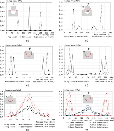
The forming process can be divided into four stages. For the small bending deformation shown in (a) in the beginning of the forming process, stage I, the contact stresses only occurred locally at the loading point in the centre and at the two supports, similar to a bending three-point beam. To further bend, stage II, the laminates (i.e. up to 110 mm), (b,c) shows that the local contact stress distribution continues but changes to resemble a four-point bending. From that point on, the tests were force-controlled because the displacement u was very small and the contact stresses began to gradually increase along the entire surface, stage III, as shown in (d). Finally, stage IV, (e) shows that the contact stress distribution is continuous and the highest contact stress is at the middle of the semicircle.
To demonstrate the influence of the product thickness Ttot on the contact stress variation, (f) shows stress variations for three different thicknesses – Ttot = 4.5, 4.9 and 5.5 mm – when the press force is F = 15,000 N.
For the thinnest product (i.e. Ttot = 4.5 mm), the contact stress on the side of the semicircle was very small, yet they were quite large at the middle of the semicircle, with the highest stress value of 1.72 (MPa). The second thickest product (i.e. Ttot = 4.9 mm) demonstrated the most widespread contact stress variations with no stress concentrations and the highest stress value of 1.35 (MPa) at the middle of the press-tool. For the thickest product (i.e. Ttot = 5.5 mm), sizeable contact stress concentrations appeared on the side of the semicircle where the reaction forces from the fixed part of the press-tool were acting very close to the applied contact forces from the movable press-tool. The contact stresses between these local stress concentrations were very small compared to the highest stress value of 3.79 (MPa), as shown in (f).
Simulation results
To illustrate the ways in which local contact points between the veneers and the mould vary during moulding, shows four different deformation states from the veneer-forming simulation, and the close-up images illustrate the locations of some of the important contact points.
Figure 6. Simulated deformation states showing contact points between the veneers and the mould: (a and b) in the beginning of the moulding process, stage 1 and (c and d) in the further part of the forming process, stage II.
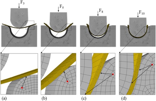
The contact zones between the mould and the veneers move during the moulding process due to the sliding of the veneers along the surface of the fixed part of the mould ((a–d)). It should be noted that the distance between the contact points of the two surfaces of the mould decreased with increased deformation ((c,d)). This distance reduction had a significant relation to the development of the press force and on the local contact forces during the moulding process.
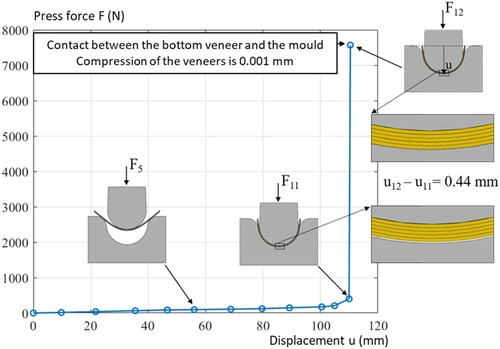
shows how the press force Fi varied with increased downward movement of the upper part of the mould. The press force increases slowly and nearly linearly during the first part of the pressing displacement of the forming process (stage I–III) thereafter the force increase drastically (stage IV, ). The force increase arises when the distance between the contact points becomes so small that clamping forces start to build up. In the fully deformed state (F11), the bottom veneer was still not in contact with the lower part of the mould in the middle. The results in illustrate a drastic increase of the press force when the veneer stack is exposed to a 0.001 mm compression in the middle of the mould (F12) (stage IV).
Figure 7. Variation of press force F as a function of downward movement of the upper part of the mould (displacement, u), at 11 specific vertical displacements (F1–F11).
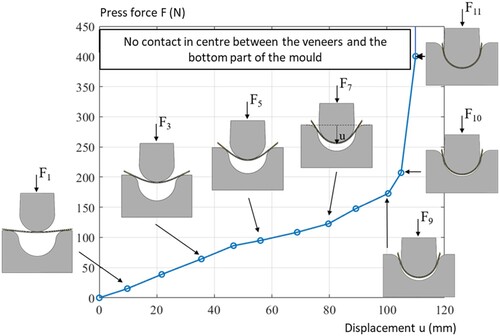
Figure 8. Variation of the press force (F) under the complete pressing cycle (F1–F12).
To study how the contact stress between the top veneer (, V1) and the upper part of the mould develops during the moulding process, shows path plots for the radial (in relation to the circle) contact stress σ22 at the 12 different deformation states shown in the previous figures.
Figure 9. Development of contact-stress variations, between the outer veneer and the upper moveable part of the mould, along path during moulding procedure at specific deformation states: (a) F1–F4; (b) F5–F8; (c) F9–F10; and (d) F11–F12.
In the beginning of the forming process, stage I, the veneer stack works as a straight beam loaded in a three-point bending ((a)). For deformation states F1–F6, shows how the radial compression stress gradually increases to −0.34 (MPa) in the centre part of the veneers until they suddenly decrease down to a constant value of −0.05 (MPa) in states F7–F8. Stage II was reached in states F7–F8. After further deformation, stage III, in states F9, the compression stress at the outer supports increases much more rapidly than the stresses in the centre area of the tool. For stage IV, in states F10–F12, the contact stress at the supports becomes so large that there is the risk for significant clamping constraints and compression failures in the veneers.
Model verification
To compare the numerical and experimental results, shows the measured and simulated press forces that are needed to reach the different press-tool positions. These force results are of a similar magnitude, but the simulated forces are relatively smaller. The simulated and experimentally based contact stress variations at different press-tool positions also demonstrated similar trends (i.e. local contact stress concentrations during most of the forming process). The static model for the veneers in the press-tool started with a three-point bending, then changed to a four-point bending after a greater bending of the veneers as the experimental test.
Figure 10. Simulated and experimentally observed press-force variation as a function of the press-tool displacement u.
Discussions
The numerical model developed in this study was used to predict deformations and stresses during the forming process of a strongly curved LVP. While the numerical and experimental results agreed well, but some differences occurred that can be attributed to measurement uncertainties and variations in parameters of individual veneers, such as stiffness and density.
In regions with high-contact stresses, considerable friction will occur between the veneers and the mould and between the veneers themselves. These friction forces may result in significant in-plane stresses which damage the veneers. This problem is often pronounced when the veneers have an uneven thickness or the moulding tools are poorly made.
The three tested total thicknesses do not follow a continuous path for the increase in the pressing forces needed. This is probably due to the different distribution of contact stresses in the different groups of laminates.
A combined experimental and numerical study to examine the influence of different parameters, such as veneer thickness, veneer orientation and opening angles of the semicircle, on local contact stress concentrations and associated crack propagation, is suggested. Further investigation is needed to understand the effect of the friction between the veneers and the mould, and between the veneer sheets. Alternative moulding methods that reduce the local stress concentrations in the veneers during moulding (e.g. hydroforming or a flexible mould methods) are finally suggested.
Conclusions
Experimental and numerical investigations were performed under lamination and simultaneously bending to study the stress distribution in the laminate. The bending of the laminate can be divided in four stages: at the beginning of the bending, the veneer contact stresses were locally distributed in a similar pattern as in a three-point bending (stage I); after the laminate was further bent, the stresses were distributed as in four-point bending (stage II); then, the contact stresses increased along the entire laminate (stage III), and finally reached a ‘peak-value’ over bent area in the middle part of the mould (stage IV). The stress distribution showed was highly sensitive to variations in the total thickness of the laminates. The experimental and the results finite-element model agreed.
Disclosure statement
No potential conflict of interest was reported by the author(s).
Additional information
Funding
References
- Blomqvist, L. (2016) Laminated veneer products: Shape stability and effect of enhanced formability on bond-line strength [Doctoral thesis, Linnæus University], Växjö, Sweden. Available at: http://lnu.diva-portal.org/smash/get/diva2:918075/FULLTEXT01.pdf
- Blomqvist, L., Berg, S. and Sandberg, D. (2019) Distortion in laminated veneer products exposed to relative-humidity variations – Experimental studies and finite-element modelling. BioResources, 14(2), 3768–3779.
- Blomqvist, L., Johansson, J. and Sandberg, D. (2013) Shape stability of laminated veneer products – An experimental study of the influence on distortion of some material and process parameters. Wood Material Science & Engineering, 8(3), 198–211.
- Blomqvist, L., Sandberg, D. and Johansson, J. (2014) Influence of veneer orientation on shape stability of plane laminated veneer products. Wood Material Science and Engineering, 9(4), 224–232.
- Dassault Systèmes (2020) Simulia User Assistance 2020: Abaqus/CAE User’s Guide (Vélizy Villacoublay).
- Hänsel, A., Sandak, J., Sandak, A., Mai, J. and Niemz, P. (2022) Selected previous findings on the factors influencing the gluing quality of solid wood products in timber construction and possible developments: A review. Wood Material Science and Engineering, 17(3), 230–241.
- Kollmann, F. F. P. and Côté, W. A. (1968) Principles of Wood Science and Technology (Berlin: Springer-Verlag).
- Navi, P. and Sandberg, D. (2012) Thermo-Hydro-Mechanical Processing of Wood (Lausanne: EPFL Press).
- Ormarsson, S. and Sandberg, D. (2007) Numerical simulation of hot-pressed veneer products: Moulding, spring-back and distortion. Wood Material Science & Engineering, 2(3–4), 130–137. doi:10.1080/17480270801945355
- Tekscan, Inc. (2020) I Scan System. Retrieved 7 January 2020, available at: https://www.tekscan.com/products-solutions/systems/i-scan-system
- Van de Velde, K. and Kiekens, P. (2002) Biopolymers: overview of several properties and consequences on their applications. Polymer Testing, 21(4), 433–442. doi:10.1016/s0142-9418(01)00107-6