
 ?Mathematical formulae have been encoded as MathML and are displayed in this HTML version using MathJax in order to improve their display. Uncheck the box to turn MathJax off. This feature requires Javascript. Click on a formula to zoom.
ABSTRACT
The design of timber floors is often governed by the fulfilment of serviceability requirements concerning human-induced vibrations. The stiffness and modal properties (eigenfrequency and damping ratio) are essential parameters for the design verification of timber floors against vibrations. In the present paper, a series of experimental tests (static tests, impact hammer modal tests, forced resonant vibrations and free vibrations) on a long-span, stressed-skin, timber floor are presented, together with predictions using a Finite Element model. Moreover, the effect of additional mass was investigated by adding extra weight in the mid-span. The modal properties obtained by different methods were in good agreement. The measured damping ratios were low, especially for the first two modes (of the order of 0.7% for the first mode and 0.8-1.0% for the second mode). The FE predictions were in good agreement with the experimental results regarding stiffness and the first two eigenfrequencies. However, the FE model overestimated the third eigenfrequency and underestimated the steady state accelerations observed under forced vibrations. A stiffness-proportional Rayleigh damping was found to describe best the energy dissipation.
1. Introduction
Timber floors are sensitive to human-induced vibrations. Restricting these vibrations within acceptable limits will usually govern their design. The calculations of vibrations according to the existing design guidelines require the modal properties (eigenfrequencies and damping ratios) and the stiffness of floors as input parameters; see for example the current version of Eurocode 5, EN1995-1-1 (CEN Citation2004) and a detailed discussion in (Zhang et al. Citation2013), as well as the draft of the new Eurocode 5 (CEN-TC-Citation2021-SC5 Citation2021). Hu and Chui (Hu and Chui Citation2004) have proposed a simpler criterion based on the fundamental eigenfrequency and the maximum deflection of a floor due to a 1kN point load. The suitability of the design criteria by Eurocode 5 (CEN Citation2004) and by Hu and Chui (Hu and Chui Citation2004) has also been verified by subjective measurements of human perception (Negreira et al. Citation2015). A comprehensive discussion on vibration serviceability aspects and parameters can be found in (Weckendorf et al. Citation2016).
Several studies have been carried out with respect to the modal properties of timber floors with relatively short spans, see for example (Weckendorf et al. Citation2008, Hamm et al. Citation2010, Jarnerö et al. Citation2010, Jarnerö et al. Citation2015, Labonnote et al. Citation2015, Opazo-Vega et al. Citation2019, Pasca Dag et al. Citation2021). In these studies, the measured damping ratios have been significantly higher than those measured in timber beams (Labonnote et al. Citation2013a) or panels (Labonnote et al. Citation2013b). Comparatively lower damping ratio values have been reported by (Nesheim et al. Citation2021). Several studies (Jarnerö et al. Citation2010, Jarnerö et al. Citation2015, Opazo-Vega et al. Citation2019) have shown that for in-situ conditions, the measured damping ratios of timber floors are significantly higher compared to laboratory conditions. However, some of the same studies (Jarnerö et al. Citation2010, Jarnerö et al. Citation2015) show that the influence of in-situ conditions is smaller with respect to the eigenfrequencies. According to a summary of vibration measurements on floors under laboratory and in-situ conditions presented by (Homb and Kolstad Citation2018), more complex structure with additional layers and couplings to bearing walls show significantly higher energy dissipation compared to simple objects. The effect of altering various structural and non-structural details on a glulam-based composite floors have been studied by (Ebadi et al. Citation2018).
Precise FE methods can be utilised to perform parametric studies and to estimate the vibrational response of floors. For example, FE models can provide estimations for some necessary input parameters for the verifications against human-induced vibrations (e.g. modes and eigenfrequencies, or point-deflection) for more complex floors and boundary conditions (since analytical expressions apply only for simple cases). Another example where FE methods could be utilised, is the estimation of the response for detailed dynamic loading, see e.g. (Casagrande et al. Citation2018).
To achieve longer spans and performant floors concerning human-induced vibrations, composite timber floors with flanges on both sides may be used due to their high stiffness. However, most studies for timber floors have been carried out for relatively short-span floors. This paper presents several experimental measurements (under laboratory conditions) and Finite Element (abbr. FE) simulations of a 9 m spanning, stressed-skin timber floor. The main objective of this study is to evaluate and compare different experimental and FE methods for the estimation of the dynamic properties of such long composite, timber floor. The acoustic performance of this type of floors is also a challenging aspect, - see e.g.(Homb et al. Citation2021)- but it is outside the scope of the present paper.
2. Materials and methods
2.1. Outline
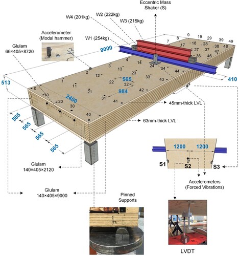
A layout and the construction details of the floor is shown in . A series of different experimental measurements were carried out on the floor to determine the stiffness and modal properties (eigenfrequencies and damping ratios), allowing comparison and evaluation of the different test methods. In particular, the following tests were performed:
static loading
impact hammer modal testing
steady-state accelerations due to resonant forced vibrations
free vibrations (shutdown after forced vibrations)
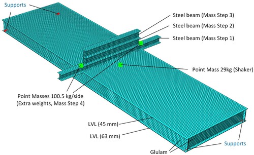
Figure 1. 3D layout of the floor and details.
The measured properties were also compared to FE predictions. The study investigated the effect of mass on the modal properties by introducing additional weight at the mid-span of the floor, in the form of steel beams. The static deflection due to the additional weight was also quantified and compared to the FE predictions.
2.2. Floor geometry and materials
The floor was constructed in 2017, and some initial measurements were taken at this time (Bjørge and Kristoffersen Citation2017). The area of the floor was 2.49.0 m2. As shown in , the floor was made of the following elements:
A frame consisting of spruce glulam beams of strength class GL30c according to EN14080 (CEN Citation2013). The frame consisted of 5 webs (two external and three internal webs with cross-sectional dimensions 140
405 mm2 and 66
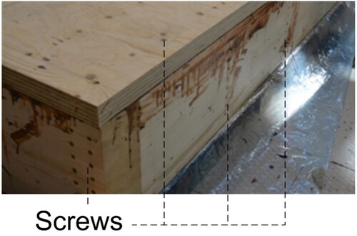
Spruce laminated veneer lumber (abbr. LVL) flanges of type Kerto-Q (VTT Expert Services Citation2013). This type of LVL consists of veneers oriented in both directions (approximately 80% and 20% in the strong and the weak direction respectively). The LVL flanges were placed with their strong direction parallel to the 9m-span. The thickness of the bottom flange was 63 mm, and the thickness of the top flange was 45 mm. The flanges were glued to the frame using two-component phenol-based glue and mounting screws with a centre distance of 300 mm (screw-gluing technique).
Figure 2. Connection of the glulam frame with self-tapping screws and flanges with glue and screws, photo by (Bjørge and Kristoffersen Citation2017).
The floor was simply supported on steel hemispheres on its four corners, see . The moisture content, measured at several points of the floor by use of an electric moisture metre, was approx. 8% on average.
Extra mass was applied at the mid-span and across the full width of the floor. The goal of the additional mass was twofold:
To measure deflections and get a reliable estimation of the stiffness of the floor. By use of these measurements, the accuracy of the FE model could be verified in this regard. The mid-span was the most suitable location for such measurements.
To study the effect of mass on modal properties of the floor. The effect of increasing mass on the eigenfrequencies is well understood and was also verified in the present study (see Section 3.2). However, more research is required with respect to the effect of mass on damping. Such data are useful in order to evaluate different models of damping in FE models (see e.g. Section 3.4)
To apply the extra mass, steel beams were placed on the floor. The different Mass Steps are provided in and illustrated in . In Mass Step 1, the steel beam was fastened to the floor by use of screws. The beams that were added on top were also fastened tightly on the bottom beams. The width of the beams (and therefore the contact width with the floor) was 200 mm. For each Mass Step, identical static and dynamic measurements were performed, as described in Section 3.
Table 1. Mass Steps and corresponding total weight.
2.3. Experimental methods
2.3.1. Static deflection measurements at the mid-span
Before the dynamic tests, all additional masses shown in were applied on the floor. The vertical static deflection at the mid-span was monitored by using three Linear Variable Differential Transformers (abbr. LVDTs). All LVDTs were placed on the bottom of the floor at the mid-span, as shown in . LVDTs S1 and S3 were placed at the two edges of the floor, while LVDT S2 was placed in the middle of the width.
2.3.2. Impact hammer modal testing
Impact hammer modal testing () was performed for each Mass Step specified in . By use of experimental modal analysis, the fundamental frequencies, the damping ratios and the mode shapes for each mode were determined (Ewins Citation2009). The frequency response function (abbr. FRF) was obtained as function of the circular frequency
by the Fourier transforms of the input force signal
and the output signal of the accelerometer
as follows:
(1)
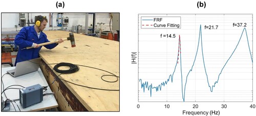
(1) The hammer by Brüel&Kjær type 8210 with a soft tip was used to excite the floor. The vertical accelerations were measured by use of a type Kistler 8770A50 accelerometer. The method used in these tests was the roving hammer method. According to the roving hammer method, the hammer load is applied and recorded on several points arranged in a regular grid pattern. At the same time, one accelerometer was fastened to a fixed point throughout the experiment. The 5
10 grid pattern of hammering points and the location of the accelerometer are specified in (points 0-49). It was desirable to avoid local deflection between the webs in order to capture the response of the floor as a whole and not local effects. Therefore, all grid points were located on points along the webs and/or the end beams. The location of the accelerometer was determined such that as many vibrational modes as possible were captured. Three hammer impacts were performed at each grid point, and the average of the obtained FRFs was used, resulting in 150 impacts per experiment. Finally, the FRFs from all the points were combined into one FRF describing the whole system, see e.g. (b).
Figure 3. Impact hammer modal tests: (a) execution and (b) example of output from Modal Parameter Identification and curve fitting (here the first mode is identified).
Prior to the experiments, preliminary impact hammer modal tests were performed with the accelerometer located very close to points 2, 4 and 22 of the grid (see ). These points were chosen based on the mode shapes of the floor obtained by FE modal analysis (see Section 2.4). Based on these preliminary tests, the accelerometer location near point 2 was deemed the most suitable to capture several modes of vibrations. This configuration was thereafter used for all subsequent impact hammer modal tests.
The data were acquired and processed using experimental modal analysis software LabVIEW (National_Instruments Citation2020) and further processed in Matlab software. The natural frequencies and the associated damping ratio for each mode were determined by curve fitting on the FRF function, see e.g. ((b)). The impact hammer modal tests also obtained the mode shape for each mode.
2.3.3. Forced harmonic vibrations
An eccentric mass shaker (developed by ANCO Engineers, type MK-102) close to the mid-span was used to apply forced harmonic vibrations on the floor, see . The shaker was fastened to the floor using self-tapping screws. For measurements under forced harmonic motions, two accelerometers were mounted to the floor: one on the top flange and one on the bottom flange, both centred at midspan (see ). All experiments and recordings began at rest before the shaker was manually and gradually tuned to the desired loading frequency. The resonance frequency (and therefore the fundamental eigenfrequency of the floor) was quantified as the frequency that maximises the steady-state response. Force harmonic vibration tests were carried out for all Mass Steps specified in . The harmonic force was applied until a steady-state response was achieved and maintained for approximately one minute. The steady-state acceleration was then quantified. Two tests were performed for each mass level at the resonance frequency, and the average test results from these tests were used.
2.3.4. Free vibrations
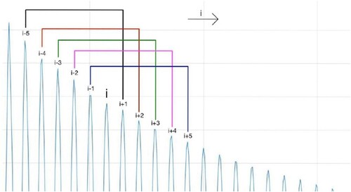
Shaker shutdown tests were also performed. Here, the shaker was shut down after the steady-state response was achieved and maintained while the accelerometers continued to record. In this way, free decaying vibration was measured, allowing for quantification of the fundamental eigenfrequency and the damping ratio in the time domain. Firstly, obtaining a signal dominated by the first mode of vibration was desired. The original signal partly met this requirement, but it was evident that it also had some higher order frequency content on several occasions. A bandpass filter around the first vibration mode was employed to obtain only frequency content corresponding to the first mode. This procedure filtered away all frequencies outside the domain of resonance
1 Hz.
The fundamental eigenfrequency was obtained by dividing the number of oscillations over the duration of the decay phase. The corresponding damping ratio was determined by use of the logarithmic decrement ( and
are peak accelerations at times
and
respectively and
is the circular eigenfrequency):
(2)
(2) The damping ratio was calculated by averaging five damping ratios according to Eq.(2) originating from the ten neighbouring peaks; the principle is shown in . In this way, several damping ratios were quantified as function of the amplitude, i.e. the amplitude dependence of the damping ratio was explored.
Figure 4. Measuring and averaging damping ratios in the decay phase.
2.4. Finite element modelling
The FE model of the floor was created by use of Abaqus software (Simulia Citation2016). The Finite Element model is shown in . The glulam webs and beams and the LVL flanges were all modelled as transversely isotropic, linear-elastic, shell elements. 4-node shell elements of the type S4R with full integration were used in all parts. The target mesh size was set to 50 mm. This mesh size was chosen based on a preliminary sensitivity study which showed that a finer mesh would not have an influence on the results. Full composite action was assumed between the webs and the LVL flanges, since the parts are jointed together by use of glue which is assumed to result in a rigid connection. The supports at the corners were modelled as pinned.
Figure 5. Finite Element Model of the floor.
The material properties for the simulations are summarised in . The elastic moduli at the reference moisture content () for glulam were obtained by EN14080 (CEN Citation2013) for GL30c and for the LVL by the corresponding European Technical Assessment (VTT Expert Services Citation2013). The mean density of each material at the reference moisture content (
) was obtained by the producers. To account for the smaller moisture content of the floor (
), the densities and the elastic moduli were adjusted. To adjust the elastic moduli, a 1.5% increase in stiffness per 1% reduction in moisture content was assumed according to (Blaß and Sandhaas Citation2017). The nominal dimensions of all elements were used in the model, i.e. the dimensional changes due to the change of moisture content were neglected (the effect of shrinkage was deemed negligible). Moreover, the mass of the self-tapping screws was also neglected in the FE model. The Poisson's ratio for glulam in is an approximation based on (Dahl Citation2009). For the LVL plates, the Poisson's ratio was assumed equal to zero, as the influence of the Poisson's ratio values on the FE results was found negligible.
Table 2. Mass Steps and corresponding total weight.
The mass of the shaker was taken into account as a point mass. The additional weight due to the steel beams (Mass Steps 1, 2, 3) was taken into account by modelling the beams, see . To model the fastening of the beams to the floor and to each other, a tie constraint was used. Finally, the extra weights in Mass Step 4, were also modelled as point masses on the top of the bottom steel plate, see .
The FE model was used:
To calculate the static deflections by use of linear elastic analysis. In this analysis, the applied load by the extra mass was modelled as a uniformly distributed line load at the mid-span.
To calculate the eigenfrequencies and the corresponding mode shapes by modal analysis.
To calculate the maximum steady-state accelerations. The FE model was used to determine the steady-state accelerations for forced harmonic vibrations with constant amplitude and varying frequency and the maximum steady-state acceleration, which occurs at resonant conditions was quantified. Several approaches were attempted to model the damping based either on modal damping or Rayleigh damping. These approaches are discussed in Section 3.4.
3. Results and discussion
This Section presents the experimental and numerical results and the corresponding discussion. The results are arranged in sub-sections where the results for each parameter - quantified by all applicable methods- are presented and discussed.
3.1. Static deflections
summarises the measured total instantaneous, mid-span deflections recorded by the 3 LVDTs and the corresponding FE predictions after each additional mass (confer ) was applied. The LVDTs did not measure the deflections due to the floor's weight; therefore, the deflections due to the weight were omitted in the FE results to facilitate the comparison. The experimental results show a linear-elastic behaviour of the floor as expected. As shown in , the agreement between the numerical and experimental results is very good. This indicates that the FE model provides a sufficient representation of the stiffness of the floor. As expected, the deflection of the floor was greater at the middle of the floor (LVDT 2) compared to mid-span deflections at the edges of the floor (LVDTs 1 and 3).
Table 3. Instantaneous deflections at the mid-span, test results vs FE simulations.
3.2. Eigenfrequencies and mode shapes
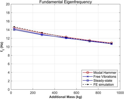
summarises the first three eigenfrequencies measured by experimental tests and calculated by the FE modal analysis for all Mass Steps presented in . Three experimental values are provided for the fundamental eigenfrequency (); namely results obtained by impact hammer modal tests, resonant steady state vibration, and free vibrations. For the second and the third mode (
and
), test results could only be obtained by impact hammer modal tests. shows the corresponding mode shapes obtained by the impact hammer modal tests, compared to the FE modal analysis results. The illustrations are provided for Mass Step 0.
Figure 6. Mode shapes (Mass Step 0).
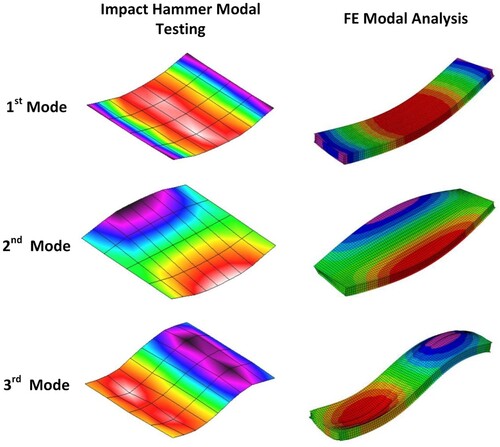
Table 4. Eigenfrequencies obtained by testing vs modal analysis results.
As shown in , the values of the fundamental eigenfrequency () obtained by free-vibrations and steady-state vibrations are slightly smaller, compared to the values obtained by the impact hammer modal tests. The FE-predictions for
are in very good agreement with the values obtained by use of the impact hammer modal tests, see also . When it comes to the higher modes (
and
) the FE model overestimates the eigenfrequency. For the second mode (
), this overestimation is quite small, i.e. the FE predictions are in good agreement with the test results. For the third mode (
), this overestimation is quite significant. As expected, increasing mass resulted in reduced eigenfrequencies for the first two modes. For the third mode, the extra mass was placed at the point of contraflexure, and the influence on the corresponding eigenfrequency was small. Moreover, it is worth noticing that the agreement between the different test methods improves as the mass increases.
Figure 7. Fundamental eigenfrequency by use of different methods as function of additional mass.
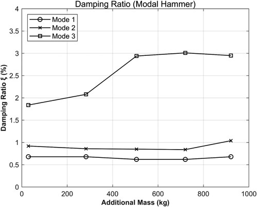
3.3. Damping ratios
summarises the measured damping ratios for the first three modes. The results from the impact hammer modal tests are also shown in . For the fundamental mode, results obtained by two different test methods (impact hammer modal tests and free vibrations) are provided. For the higher modes, results could only be obtained by the impact hammer modal tests. It should be emphasised that these values reflect the laboratory conditions, which result in smaller damping than in-situ conditions, as found in (Jarnerö et al. Citation2010, Jarnerö et al. Citation2015, Opazo-Vega et al. Citation2019). According to the impact hammer modal tests, the damping ratio at the fundamental mode is of the order 0.6-0.7%.
Table 5. Test results for damping ratios.
A small amplitude dependence was observed in the results obtained from free vibrations, see and . According to these measurements, the damping ratio for the fundamental mode decreases for decreasing amplitude and it is slightly higher for smaller mass. Note that for decreasing amplitude, the value of the damping ratio measured by free vibrations is ‘converging’ towards the values measured by the impact hammer modal tests.
Figure 8. Damping ratio for the fundamental mode, measured by free vibrations as function of amplitude.
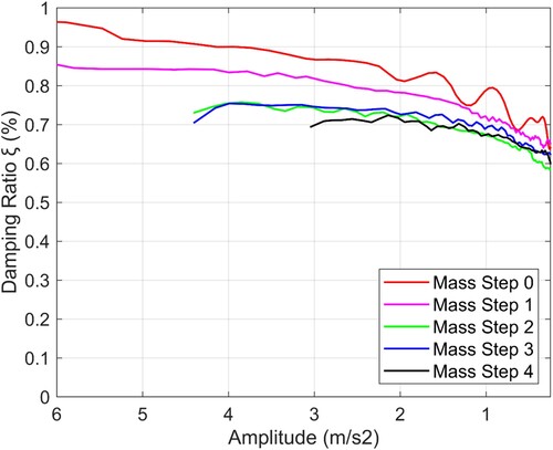
Figure 9. Damping ratios per mode measured by the impact hammer modal tests.
These measured damping ratio values are quite low compared to results in the literature, which are typically available for shorter span floors, see, e.g. (Weckendorf et al. Citation2008, Jarnerö et al. Citation2010, Jarnerö et al. Citation2015, Labonnote et al. Citation2015, Opazo-Vega et al. Citation2019). Two facts may explain this finding: firstly, the floor is quite long and therefore dominated by bending deformation of the webs and axial/bending deformation of the panels, while shear deformation is less significant. Available experimental results for timber beams (Labonnote et al. Citation2013a) show a smaller damping ratio of elements subjected predominantly to bending stresses compared to elements where shear is significant. In fact, the damping ratio values by use of impact hammer modal tests are quite similar to the values obtained for slender, bending-dominated timber beams (Labonnote et al. Citation2013a) by using the same technique. Secondly, in the main load-transfer region, which is the interface between the webs and the flanges, a rigid glued connection was used, presumably resulting in lower damping than a connection where mechanical fasteners carry the stresses.
According to the impact hammer modal tests (also in ), slightly higher damping ratios were obtained for the second mode (is of the order of 0.8-1.0%) and significantly higher values for the third mode (
is of the order of 2.0-3.0%). Finally, no clear conclusion could be reached on whether the mass has an influence on the damping ratios based on the values presented in . This is in contrast to the findings by (Weckendorf et al. Citation2008), where increased mass resulted in significantly lower damping ratio for the first two modes.
3.4. Steady-state accelerations at the resonant frequency
summarises the test and FE results with respect to steady-state accelerations at resonance for the different Mass Steps (and the corresponding amplitude of the harmonic force). With respect to energy dissipation, ,
have been used as estimates of the damping ratios based on the results presented in . Several approaches have been used in the FE analyses to model damping. In particular:
Modal damping.
Rayleigh damping with stiffness and mass coefficients (
Stiffness-proportional Rayleigh damping (
Mass-proportional Rayleigh damping (
Table 6. Steady state accelerations at resonant response, Test vs FE results.
As shown in , all FE predictions underestimate the experimental steady-state accelerations. The stiffness-proportional Rayleigh damping provides the best estimations, especially in the case where the stiffness coefficient is calibrated to match the test result for Mass Step 0. On the other hand, the highest underestimation occurs for the mass-proportional Rayleigh damping.
4. Conclusive remarks
The design of timber floors is often governed by comfort criteria related to human-induced vibrations. The fulfilment of such criteria may impose limitations on their span. The response of timber floors subjected to vibrations depends largely on their modal properties (eigenfrequencies and corresponding damping ratios). The main objective of this paper was to quantify and compare the modal properties of a long-span, stressed-skin, timber floor obtained by use of different experimental methods (impact hammer modal testing, steady-state resonant forced vibrations and shaker shut-down free vibrations) and Finite Element (FE) modelling. Moreover, the effect of additional mass on the modal properties was explored. Static deflection measurements were also carried out and compared with the FE model. The following main conclusions are drawn:
The measurements of the fundamental eigenfrequency were generally in good agreement with each other and the FE predictions, with minor deviations. For the 2nd eigenfrequency, a reasonably good agreement between the impact hammer modal tests and the FE prediction was observed. The FE model significantly overestimated the 3rd eigenfrequency.
The measured damping ratios corresponding to the first two modes were small (of the order of 0.7% for the first mode and 0.8-1.0% for the second). The damping ratio for the third mode was significantly higher (of the order of 2.0-3.0%). According to the free vibration measurements, the damping ratio for the fundamental mode is amplitude dependent.
Increasing mass resulted, as expected, in lower fundamental eigenfrequency. However, no clear conclusion could be reached with respect to the influence of additional mass on the damping ratio.
The FE predictions for the static deflections were in good agreement with the experimental results. On the other hand, the FE predictions for the resonant steady-state acceleration were significantly lower than the corresponding experimental results. This underestimation was the smallest when stiffness-proportional Rayleigh damping was used in the FE model.
Author contribution
All authors have seen and approved the manuscript and have contributed significantly to its preparation. Einar Sagerud, Jørgen Bjerve and Haris Stamatopoulos share the first-authorship. Einar Sagerud and Jørgen Bjerve performed and post-processed all the experiments, contributed to FE models and contributed to the writing of the manuscript. Haris Stamatopoulos supervised the experimental work, performed FE simulations and wrote most of the manuscript. Kjell Arne Malo developed the layout and supervised the construction of the floor element. Anders Rønnquist has provided useful advice for the dynamic tests. Anders Rønnquist and Kjell Arne Malo have critically reviewed the manuscript.
Acknowledgements
The first two authors would like to acknowledge their employers (Norconsult and COWI, respectively) for allocating time resources to prepare this manuscript. Master Students Henning Bjørge and Terje Kristoffersen constructed the floor in 2017, and this contribution is kindly acknowledged. The authors would also like to thank Osama Abdelfattah Hegeir for his contribution to the artwork.
Disclosure statement
No potential conflict of interest was reported by the authors.
Additional information
Funding
References
- Bjørge, H. and Kristoffersen, T. (2017) Conceptual study of wooden composite floors with possibility of rigid attachment to glulam columns. Master’s Thesis. Norwegian University of Science and Technology.
- Blaß, H. J. and Sandhaas, C. (2017) Timber Engineering-Principles for Design. Karlsruhe, Germany: Karlsruher Institut für Technologie (KIT), KIT Scientific Publishing.
- Casagrande, D., et al. (2018) Analytical, numerical and experimental assessment of vibration performance in timber floors. Engineering Structures, 168, 748–758.
- CEN (2004) NS-EN 1995-1-1:2004 + A1:2008 + A2:2014 + NA:2010. Design of timber structures - Part 1-1: General - Common rules and rules for buildings. Brussels: European Committee for Standardization. pp. 56–58.
- CEN (2013) EN 14080-2013: Timber structures- Glued laminated timber and glued solid timber - Requirements. Brussels, Belgium: European Committee for Standardization.
- CEN-TC-250-SC5 (2021) prEN 1995-1-1 (draft). Design of timber structures -Common rules and rules for buildings - Part 1-1: General. European Committee for Standarization.
- Dahl, K. (2009) Mechanical properties of clear wood from Norway spruce. Ph.D. Thesis. Norwegian University of Science and Technology.
- Ebadi, M. M., Doudak, G. and Smith, I. (2018) Vibration responses of glulam beam-and-deck floors. Engineering Structures, 156, 235–242.
- ETA Danmark A/S, 2013. European Technical Approval ETA-12/0114.
- Ewins, D. J. (2009) Modal Testing: Theory, Practice and Application (2nd Edition). Baldock, United Kingdom: Research Studies Press.
- Hamm, P., Richter, A. and Winter, S. (2010) Floor vibrations - New results. ed. 11th World Conference on Timber Engineering 2010, WCTE 2010, 2010, 2765-2773.
- Homb, A., et al. (2021) Sound insulation of timber hollow box floors: Collection of laboratory measurement data and trend analysis. Building Acoustics, 28(2), 161–183.
- Homb, A. and Kolstad, S. T. (2018) Evaluation of floor vibration properties using measurements and calculations. Engineering Structures, 175, 168–176.
- Hu, L. J. and Chui, Y. H. (2004) Development of a Design Method to Control Vibrations Induced by Normal Walking Action in Wood-Based Floors. Proceedings of the 8th World Conference on Timber Engineering. Lahti, Finland, 217-222.
- Jarnerö, K., Brandt, A. and Olsson, A. (2010) In situ testing of timber floor vibration properties. ed. Proceedings of WCTE 2010: World Conference on Timber Engineering Riva del Garda,Trentino, Italy.
- Jarnerö, K., Brandt, A. and Olsson, A. (2015) Vibration properties of a timber floor assessed in laboratory and during construction. Engineering Structures, 82, 44–54.
- Labonnote, N., Rønnquist, A. and Malo, K. A. (2013a) Experimental evaluations of material damping in timber beams of structural dimensions. Wood Science and Technology, 47(5), 1033–1050.
- Labonnote, N., Rønnquist, A. and Malo, K. A. (2013b) Semi-analytical prediction and experimental evaluation of material damping in wood panels. Holzforschung, 67(3), 333–343.
- Labonnote, N., Rønnquist, A. and Malo, K. A. (2015) Prediction of material damping in timber floors, and subsequent evaluation of structural damping. Materials and Structures/Materiaux et Constructions, 48(6), 1965–1975.
- National_Instruments (2020) Modal Analysis in LabVIEW (https://www.ni.com/en-no/innovations/white-papers/09/modal-analysis-in-labview.html).
- Negreira, J., et al. (2015) Psycho-vibratory evaluation of timber floors – Towards the determination of design indicators of vibration acceptability and vibration annoyance. Journal of Sound and Vibration, 340, 383–408.
- Nesheim, S., Malo, K. A. and Labonnote, N. (2021) Effects of interconnections between timber floor elements: dynamic and static evaluations of structural scale tests. European Journal of Wood and Wood Products, 79(5), 1163–1182.
- Opazo-Vega, A., Muñoz-Valdebenito, F. and Oyarzo-Vera, C. (2019) Damping assessment of lightweight timber floors under human walking excitations. Applied Sciences, 9(18), 3759.
- Pasca Dag, P., et al. (2021) Dynamic characterization of timber floor subassemblies: sensitivity analysis and modeling issues. Journal of Structural Engineering, 147(12), 05021008.
- Simulia, D. S. (2016) Abaqus/CAE 2017.
- VTT Expert Services (2013) European Technical Approval ETA-13/0504: Metsä Wood Kerto glued components.
- Weckendorf, J., et al. (2008) Damping characteristics of timber flooring systems with respect to Low-frequency vibration modes. 10th World Conference on Timber Engineering 2008, 4.
- Weckendorf, J., et al. (2016) Vibration serviceability performance of timber floors. European Journal of Wood and Wood Products, 74(3), 353–367.
- Zhang, B., et al. (2013) Comparison of vibrational comfort assessment criteria for design of timber floors among the European countries. Engineering Structures, 52, 592–607.