
 ?Mathematical formulae have been encoded as MathML and are displayed in this HTML version using MathJax in order to improve their display. Uncheck the box to turn MathJax off. This feature requires Javascript. Click on a formula to zoom.
ABSTRACT
This study investigates the influence of different machining processes on the tensile shear strength of glued lumber, focusing on optimizing the tool geometry of face milling. The data obtained were analyzed using statistical methods. The roughness of the surface produced by the machining process and the damage to the microstructure under the cutting edge are identified as important factors influencing the quality of the bond. The results show that the optimized process (low roughness and microstructure damage) leads to more effective gluing.
1. Introduction
For structural timber engineering in Germany, only adhesives with a building authority approval from the Deutsches Institut für Bautechnik (DIBt) are permitted for load-bearing purposes. The decisive criterion is the quality of the adhesive used, that is, the adhesive should satisfy the standard tests for moisture resistance. Therefore, for example, the tensile shear strength is tested according to the EN 302-1 standard, and the bearing sequence (A1, A4, and A5) and delamination resistance are tested according to EN302. Among these tests, the delamination test is the most difficult to satisfy. During the delamination test, a significantly complex process is used to apply the stress (soaking in the autoclave, drying at an elevated temperature of 65°C and 12.5% ± 2% relative humidity, and air circulation during the high-temperature process). Owing to the high moisture content, stress profiles across the cross-section, which must be transferred from the glued joints, promote the opening of the joints, leading to delamination. The differences between the two test methods lie in the more pronounced moisture profile, thus leading to higher stresses in the adhesive joint during the delamination test.
Generally, for hardwood and special softwoods such as larch, additional priming of the surface is necessary when bonding with 1C-PUR to satisfy the standard requirements. Spruce, on the other hand, can be bonded without any problems.
Currently, forest conversion is being focused on producing more hardwood; therefore, more hardwood is being made available. However, owing to the increasingly dry climate more resistant softwood species such as Douglas fir are grown. Therefore, in the long term, newer and more drought-resistant wood species, in addition to spruce, may be increasingly used (Luciana et al. Citation2021). Thus far, softwood (mostly spruce) has dominated the timber construction industry because of its good density-to-strength ratio and lower cost. For example, in Switzerland, the price per m3 of glulam made of hardwood is 3–4 times higher than that of softwood. Therefore, it is more of a niche product for special applications and is often used because of its appearance. In delamination testing and tensile shear testing, the influence of the type of surface treatment has been extensively studied.
The quality of bonding of wood used in structural timber engineering is determined by various factors. The important parameters are as follows (Hänsel et al. Citation2022, Niemz and Dunky Citation2023a and Citation2023b):
- the properties of the wood used, such as wood species, annual ring orientation, wood moisture content, and wood moisture content difference between the lamellae to be bonded;
- the type of adhesive, including its adhesion properties, cohesion properties, moisture dependence such as adhesion and cohesion, and strength and elasticity of the glued joints;
- the type of treatment of the wood surface prior to bonding, such as circumferential milling, face milling, sanding, finishing; for instance, circumferential milling causes damage in the area near the surface (Westkämper and Riegel Citation1993a and Citation1993b, Riegel Citation1997, Rehm, Citation2002);
- the mechanism of bonding, such as the pressure and pressure distribution over the length of the bonded element, and temperature and humidity during bonding.
The previous studies conducted in this area are described in this section.
Knorz (Citation2012) tested the bonding of beech and ash determined the differences between two different MUF resins and 1C-PUR. It was found that 1C-PUR achieved the standard specifications with primers. The better of the two MUF systems was slightly above the permissible standard specification of a maximum of 5%. Sanding produced worse results than planing in the delamination test for ash (Knorz Citation2012).
Kläusler et al. (Citation2014) obtained slightly better values for face milling than for planing with sharp cutting edges when comparing planing (sharp and blunt cutting edges), face milling, and grinding (grit 80 and 120) on tensile shear specimens using 1C-PUR (HBS 309, Henkel); grinding produced similar results to planing with sharp cutting edges. Blunt cutting edges led to a significant decrease in shear strength after bearing sequence A4.
Ammann (Citation2015) and Ammann et al. (Citation2016) could not meet the standard requirements for delamination (maximum 5%) in an industrial bonding of ash glulam; face milling and planing was as a processing method for 1C PUR and 2 MUF resins. In the case of MUF, face-planed surfaces were also used. In terms of tensile shear strength, face milling positively influenced a 1C PUR at Ammann, but not on the second system (there were two different manufacturers). Thus, the difference between the adhesive systems of a chemical group is recognizable in this case.
Grüll et al. (Citation2016) investigated the surfaces of face-milled and planed spruce wood. The tensile shear strength was also tested. Face planing produced a smooth-re (macrostructure) surface than conventional planing. The differences in tensile shear strength (A1) were insignificant. However, the lower tensile shear strength of spruce compared to hardwood is a critical factor in this case, thus affecting the transfer of stresses in the glued joint. In addition, a positive influence of face milling on the bonding quality was reported in a previous study (Ritar Citation2002a, Ritar Citation2002b, Ritar Citation2002c).
Moanda et al. (Citation2022) investigated the influence of planing with a microstructured surface on the bond quality of glulam made of beech. A slight improvement was observed in both the tensile shear strength in Storage Sequence A4 and the delamination test compared to conventional planing. The best results were observed in the case with the finer microstructure. However, a planned reduction of the adhesive content was not possible.
Usually, the combination of face milling and 1C-PUR is successfully applied in practice for softwood (spruce, also Douglas fir), sometimes in combination with primers such as larch. A slightly rougher surface often leads to better results than a very smooth surface.
Influences on the wetting behavior and roughness are often difficult to quantify in the case if wood because of the naturally strong porosity and the extensive variability of wood in terms of differences between early and late wood and influence of growth conditions.
Overall, the inferences drawn from the results regarding the influence of chipping on bonding are not always clear. This may be because most existing studies focused on bonding and not on chipping. Technical changes in the type of grinding (calibration grinding, grinding for surface finishing, service life of the cutting edges, and their blunting) were of secondary importance.
The positive effect of priming with DMF was clearly evident in the study by Kläusler (Citation2014) and Kläusler et al. (Citation2014) and Ammann (Citation2015) and Ammann et al. (Citation2016). PRF (Aerodux A185) met the requirements in both the delamination and tensile shear tests. This is widely used as a reference.
Currently, when bonding with 1C-PUR in Loctite adhesives from Henkel, the surface is pre-treated with a surfactant-based primer for hardwood and selected softwoods (e.g. larch). DMFFootnote1 served only as a model substance in the first phase. Even with the HMR primer, the requirements for tensile shear strength according to Storage Sequence A4 were met (Kläusler Citation2014). Kläusler (Citation2014) also tested other primer systems such as water, DMF, HMR,Footnote2 and pMDI.Footnote3 Although the HMR primer and DMF produce comparatively good results, both methods are not practically applicable owing to their price and occupational health and safety for DMF, in addition to extremely long exhaust air time and formaldehyde release for HMR. The effect of HMR primers is described in detail in a previous study (Boeger et al. Citation2022). However, relevant work is ongoing for surfactant-based primers.
After priming with surfactant-based primers, the requirements of the delamination test are met for hardwoods and selected hard-to-bond softwoods such as larch for 1K-PUR. Without primers, the requirements are generally not met for 1C-PUR for hardwood. In general, priming requires exact compliance with the technical specifications in terms of application quantity, concentration, waiting time, and suitable 1C-PUR systems. Primers are now available for several different PUR systems.
Spruce does not require priming, and larch does not meet the specifications without priming. In the case of Douglas fir, priming is not necessary in some cases, depending on the adhesive and processing method, but optimized processing such as face milling can have a positive effect. The necessity of priming tends to apply more or less to all 1C-PUR systems and hardwood or larch, also in addition to selected overseas softwoods.
However, the overall condition is partly inconsistent. The differences in the stress on the test specimens during the tensile shear strength and delamination tests as well as those in terms of the wood species should be considered. If spruce is used, the shear strength of the wood is significantly lower than that for red beech or ash. If only A1 (i.e. dry tested) is used, the moisture stress is neglected. Therefore, the A1 specifications are easily met by most adhesives. The delamination test leads to a significantly higher stress compared to the tensile shear strength owing to the larger dimensions and the stress on the bonded joint caused by the effects of water and drying. However, the general trend is that if the standard specification is not achieved for the lap shear strength and the A4 bearing sequence, the delamination test is usually not cleared. The delamination test is significantly harder to clear than the lap shear test because of the larger dimensions and higher stresses in the glue joints.
The practical conditions of use, especially in a dry indoor climate, often deviate significantly from those used during testing the moisture resistance of the bonded joints according to EN 302-1 and EN 302-2. Often, even in dry indoor climates, especially in winter in heated rooms with extremely low relative humidity, problems occur due to residual stresses, cracks, and delamination caused by the low relative humidity (Niemz Citation2022).
If possible, processing should be done immediately before bonding to prevent moisture changes on the surface and aging. This prevents drying of the wood in the surface area (especially during winter when the relative humidity in the halls is significantly low). If the wood moisture content is too low, or if the relative humidity is low in winter in heated, non-air-conditioned production halls, the water available for curing in the area of the adhesive joint in the case of 1C-PUR is insufficient. However, oxidation processes caused by ingredients and the influence of the ingredients themselves can also impair curing. The problem of bonding larch wood with 1C-PUR is well known (Kuenniger et al. Citation2006). Studies on the influence of extractives on the curing of 2C-PUR adhesives were carried out by Bockel et al. (Citation2019), and Bockel (Citation2020), among others.
In summary, the processing procedure considerably influences the bonding quality, thus indicating scope for optimization. Furthermore, the damage caused by the machining process has thus far been investigated only rudimentarily for selected machining processes and has usually been of secondary importance in bonding tests.
Therefore, the present study examines whether further optimization of the tool can be achieved with face milling by using rounded cutting edges to realize improved bonding quality. As the process can be further developed by optimizing the geometry of the cutting edges during face milling, this study attempts to address the same.
2. Influence of machining processes on surface properties
The various machining processes used in the process influence the micro- and macrostructures of the surface and affect the edge areas below the surfaces produced. The associated influences on wetting, adhesion, and formation of an adhesive joint filling the wood structure three-dimensionally, as well as swelling associated with water exposure determine the strength of the bond. A review of the various theories of adhesion is given in Zeppenfeld and Grunwald (Citation2005), Paris et al. (Citation2014), Habenicht (Citation2017), Jakes et al. (Citation2019) Suchsland (Citation1958), and in Chapt. 14.2 included in Niemz et al. (Citation2023). In industrial applications, rougher surfaces lead to better results in terms of tensile shear strength and delamination when bonding with 1C PUR adhesives, thus supporting the approach that mechanical adhesion significantly contributes to the bonding of wood. Therefore, various processing methods were initially investigated to study their effect on the bonding of beech using only a single component PUR adhesive as an example. Beech was used to achieve a high load on the glued joint (see also EN 302-1). Ideally, the primers can be replaced by suitable machining processes or can be optimized. However, this cannot be practically realized for hardwood.
First, the fundamental effects of machining on the quality of surfaces were studied previously by Stewart (Citation1980, Citation1984) and Stewart et al. (Citation1982). It was found that the destruction caused during milling and grinding under the machined surface depends on the technological parameters such as feed rate, engagement size, and wood moisture content. In face milling, the destruction in near-surface areas is relatively low (Stewart Citation1984). For sanding, the technique clearly influences the surface quality (sanding thickness). Further, Westkämper and Riegel (Citation1993a), Westkämper and Riegel (Citation1993b), Riegel (Citation1997), Rehm (Citation2002), Gottloeber (Citation2014), and Troeger and Schneider (Citation2015)provide a good overview on the influence of different machining processes as planing, grinding, and face milling.
Depending on the machining process of the technical parameters such as feed rate and cutting speed, certain microstructural damage occurs in all processes. For example, structural damage occurs during calibration grinding due to high stock removal thicknesses. In face milling, the effect of destruction and/or plastic deformation is less pronounced (Stewart Citation1984). Numerous technological parameters such as feed rate, rotational speed, and blunting of cutting edges affect the microstructure. The specific variety of wood also strongly influences the wood moisture content, fiber angle, and fracture mechanical properties. This also applies to sanding. The wetting angle, adhesion of lacquers, or bonding properties are considerably affected.
Overall, the influence of machining on bonding quality is yet to be investigated in detail. There are starting points for a larger project with a combination of modern investigation methods, also in the microscale. However, previous studies are mainly limited to the roughness, waviness, and the wetting behavior, which are usually less applicable for wood. Further, as modern methods such as AFMFootnote4, synchrotron, and X-ray microtomography have a high resolution, the interactions are often not adequately detected. Moreover, fracture mechanics approaches are also conceivable (Ammann Citation2015, Ammann and Niemz Citation2015). Measurements with DICFootnote5 under high resolution in combination with fracture mechanics are also possible. However, a damaged surface of particle materials (impact chips instead of cutting chips) leads to a significant increase in creep deformation; however, it also results in a decrease in strength (Niemz and Sonderegger Citation2021).
2.1. Overview of face milling processes
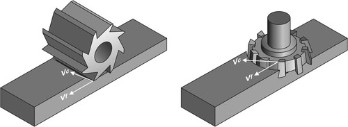
Generally, circumferential face milling is used for processing wooden surfaces. A special subdivision of the milling processes is made in DIN 8589 Part 3. According to the type of tool engagement, a distinction is made between circumferential, face, and face-circumferential milling ().
Figure 1. Face milling method according to DIN 8589 Part 3. left: circumferential face milling (planing), right: face milling, vc: cutting speed, vf: feed rate (following DIN 8589-3).
The basic principles are described in Tröger (Citation1990), Heisel and Tröger (Citation1991), Heisel and Troeger (Citation1993), Tröger and Schneider (Citation2015), among others.
2.1.1. Fundamentals of face milling
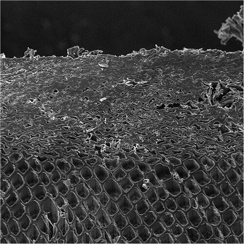
As the cutting edge progressively cuts through the material, an ever-widening wear bevel is created, increasing the forces introduced into the workpiece, thus negatively affecting the structure. For example, when machining wood with continuous cutting-edge wear, a layer of compressed cells is developed (); this is referred to as the deformation zone. This layer of compressed cells affect the bonding quality. The compressed zone makes it more difficult for the adhesive to penetrate; in the case of water-soluble adhesives, the compressed zone may swell back (the swell increases with increasing density).
Figure 2. Compacted zone of the wood structure after milling with the blunted cutter 1, cutting with the fiber (compaction depth 250 µm); Scale 1,200. Source: PhD thesis K. Rehm, TU Dresden.
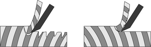
A significant influence on the machining quality depends on whether the chip is cut in climb milling or up-cut milling. Thus, a comma-shaped chip is formed that is cut either from its tip (up-cut) or from its strongest side (climb milling).
Chip formation begins in the up-cut only when the chip thickness h is greater than the wear factor h1; then, the surface and machining quality are already realized. Therefore, the surface in up-cut milling is produced under unfavorable technological conditions. However, in climb milling, the chip is cut on its thick side, the chip thickness gradually decreases, and the cutting edge abruptly emerges from the material while it is still cutting; therefore, surface compaction is not as intensive as in up-cutting.
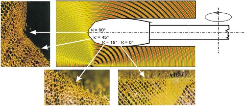
Another disadvantage of circumferential face milling in up-cut mode is the strong dependence of the surface quality on the angle between the cutting and grain directions (). This varies with the structure of the wood (e.g. in the knot area, influence of the annual ring position, and the fiber-load angle).
Figure 3. Influence of the angle between cut and grain direction on the quality of the surface.
2.1.2. Influence of micro-geometry of the cutting wedge
Owing to the wear chamfer formed during machining, an increased wedge angle occurs in the micro area, stabilizing the fracture-prone cutting wedge so that no further chipping occurs.
2.2. Face milling
b illustrates the principle of face milling. Especially for larger machining widths, the process ensures vibration-free workpiece guidance. The tool is tilted by a few hundredths of a millimeter so that the back-rotating cutting edge does not come into contact with the workpiece. Significantly smooth surfaces can be achieved with a face milling cutter.
The reason for the significantly improved machining quality is the reduced chip thickness in the quality-forming area due to the setting angle. The potential of face milling is shown in .
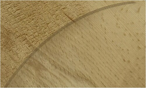
Figure 4. Comparison of surface finish (top: sawn, bottom: face milling). Source: BA Sachsen.
2.2.1. Macrogeometry of the generated wood surface
As the natural roughness of the structure is caused by the planar incision of the wood cell structure, it always appears anatomically; however, the kinematic roughness results from the cycloidal relative movement path between tool and workpiece. Machining marks, that is, knife marks (), are produced, with a periodic wave shape (Heisel et al. Citation1991a, Citation1991b) if the cutting edges on the tool are set precisely, the setting variables are constant, and disturbance variables such as vibrations are neglected.
Figure 5. Valley quotient according to Neusser cited in (Troeger and Schneider Citation2015); Dependence on (fz) and (d). Source: IfW.
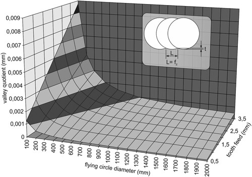
These characteristics of macrogeometry are crucial in evaluating a wood surface. Neusser (Neusser and Krames Citation1971) defines a valley quotient (T), as the ratio of the height of the waves (t) and the width of the valley (L):
(1)
(1) (Ettelt Citation1987) describes the wave height (t) caused by the so-called “knife blows” as follows:
(2)
(2) this is why (T) is valid for the valley quotient:
(3)
(3) where fz = tooth feed =
; n = speed, and z = number of cutting edges (4).
shows the valley quotient as a function of tool diameter and tooth feed.
The lower the valley quotient (T), the less visible the machining marks (for example, the blue area in ). The smaller the tooth feed and the larger the pitch circle diameter, the more difficult the observation of these machining marks. For example, in taper face milling (radius of curvature of the rake arc is approximately 500 mm), no knife marks are visible. In face milling, the face blades can be crowned with a large radius of curvature (Westkämper and Riegel Citation1993a and Citation1993b, Westkamper and Schadoffsky Citation1995a and Citation1995b), indicating that the machining marks, which are certainly still present, are no longer visually recognizable. As the wave height of the knife impacts in practice is of the order of approximately 2–6 µm, the high precision with which the tool should be manufactured and maintained is evident.
2.2.2. Design of the transition from the peripheral to the face cutting edge
If the circumferential and face cutting edges are perpendicular to each other, a deformation zone is developed below the face cutting edge, forming spatially around the cutting edge corner. This can only be eliminated by multiple cutting edges with gradually decreasing setting angles, i.e. decreasing deformation depth. The best results are achieved with a final crowned cutting edge section, where the curvature means that the cutting edge corner at the end of the blade can no longer form on the surface. In the area of the horizontal tangent of the crowned cutting edge section, the setting angle is κ = 0°, i.e. no further cutting occurs, and the cutting edge only smoothes the surface. This effect, shown here in the example of circular sawing with crowned secondary cutting edges, can also be used in face milling ().
Figure 6. Deformation zone when sawing softwood with convex secondary cutting teeth. Source: unpublished lecture notes “Fundamentals of woodworking” IfW Stuttgart.
With knives with crowned secondary cutting edges, it is practically possible to create deformation-free cells in the surface of solid wood. As the setting angle decreases, the deformation depth (thickness of the compressed cell layer) also decreases.
2.3. Machining the specimen surface via finishing
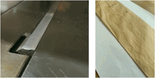
The principle of finishing corresponds to the operation of a hand plane, i.e. machining with linear feed motion. The cutting speed and feed rate are maintained constant.
To improve the surface, the blade can be set at an angle, thus reducing the effective wedge angle (wedge angle in the cutting direction) and making the blade sharper. Finishing with a sharp cutting edge results in significantly smooth surfaces, free of machining marks and low cell deformation. However, the depth of deformation increases with increasing wear of the knife.
shows the tool of the finishing machine and a chip produced by fining.
Figure 7. Finishing tool and (exemplary) chip of a finished beech wood surface. Source: BA Sachsen.
2.4. Sanding
A previous study (Riegel Citation1997) investigated the influence of various machining processes on the surface quality. In this previous study, microstructure damage was found during calibration sanding with high mesh sizes. This study referred to the findings reported by Stewart (Stewart Citation1980). Depending on the feed rate, microstructural damage can occur both in milling and calibration sanding. Cutting speed also affects the microstructure; this was demonstrated for milling in studies by Fischer (Citation1996) and Fischer et al. (Citation1980). Here, Fischer et al. (Citation1980) applied photogrammetry to quantify the destruction under the cutting edge. A similar approach would be conceivable today using digital image correlation and a high-speed camera.
3. Test material and methodology
3.1. Test overview: Influencing variables on the die side
shows the test overview. The bonding quality of 1C-PUR was tested with five different processing variants.
Table 1. Test overview.
Beech (Fagus Sylvatica L.) with a density of 670 ± 75 kg/m3 and a moisture content of 12% was used for the tests. It was bonded with a specific pressure of 1 MPa over a pressing time of 3 h.
3.2. Surface processing
For all specimens, according to the EN302-1 standard, the required thickness of 5 mm was produced immediately before bonding by removing the oversize of 1 mm using the following processing methods.
Technological influencing variables:
Circumferential milling with sharp cutting edge (variant 1) and dull cutting edge (variant 2).
Cutting material: Tersa HSS cutting edge.
Angle during cutting: wedge angle = 50°, rake angle = 15°, clearance angle = 25°.
The cutting edges were blunted by repeatedly planing the 0.8-mm-thick MF face layer of a 19-mm-thick MF-coated particleboard. A total of 10–15 m of MF face layer was planed. A strong rounding of the knife edge, which is larger than that with usual working sharpness, is evident. These special planing knives do not have a wear mark as the standard for better clarity of exceeding the working sharpness. In practice, the knives are changed according to specially defined and subjective intervals.
The processing of the specimens immediately before bonding to the thickness of d = 5 mm was carried out with a T45 thickness planer from the manufacturer “MARTIN” under the following conditions:
speed (n) = approximately 5000 rpm
cutting speed: = 18 m/s
feed speed (vf) = approximately 6 m/min
number of teeth (z) = 1
size of engagement (e) or machining allowance = 1 mm
flying circle diameter (D) = 125 mm
(b) Face milling with straight cutting edge (variant 3) and crowned cutting edge (variant 4)
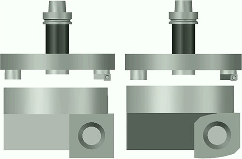
To eliminate radial and axial runout, the surface was machined with a single-edged test tool () availed from the Institute for Machine Tools (IfW) at the University of Stuttgart.
Figure 8. Test setup for face milling: Left straight cutting edge, right crowned cutting edge.
The machining was carried out with a CNC machining center of the type LeanFactory BAZ from the company HOMAG Group AG in the machining laboratory of the BA Saxony under the following conditions:
speed (n) = approximately 3200 rpm
feed rate (vf) = 6 m/min
number of teeth (z) = 1
mesh size (e) or machining allowance = 1 mm
flight circle diameter (D) = 240 mm
(c) Sanding (variant 5)
Sanding was performed with an industrial wide belt sanding machine of the type HOMAG Bütfering SWT 325QC. The machine has two different sanding units for separate processing along and across the grain direction.
Grain size P80 with rigid engagement (calibration roller or steel roller)
Sanding direction: longitudinal to the grain
Material removal: 1 mm
Feed rate of conveyor belt: 6 m/min
(d) Fining (variant 6)
Fining was carried out with a Murunaka type finishing machine. To improve the surface quality, the knife was arranged at an angle, thus reducing the effective wedge angle (wedge angle in the cutting direction) and making the knife sharper.
25° inclination of the knife, removal (engagement) of approximately 0.1 mm to a thickness of 5 mm (initial thickness was 6 mm) due to the design.
Machining: feed direction and cutting direction relative to each other (counter-rotating)
Cutting speed: 6 m/min
Feed rate: 6 m/min
Depth of cut: approximately 0.2 mm
3.3. Characterization of the surface
The roughness and waviness of all the test specimens were measured in the dry condition as well as after moistening, i.e. after spraying 13 g/m² of water and re-drying. The measurements were made within the board center using the ConturoMatic CV250 tactile measuring device from T&S Gesellschaft für Längenprüftechnik (s.a.DIN 4776 Citationn.d). The following test conditions were applied:
v (mess) = 1.75 mm/s
Specimen dimensions: approximately 650 × 140 × 5 mm
Length of measuring section: lengthwise 200 mm
Length of measuring section: crosswise 50 mm (3× lengthwise and 1× crosswise to the fiber)
R-values: M = 1:1200 and cut-off = 2.5 mm
W-values: M = 1:1200 and cut-off = 2.5 mm
3.4. Bonding
The lamellas were processed approximately 20 min before bonding. Before processing, the wood was stored in a normal climate of 20°C/65% relative humidity. Before gluing, the lamella thickness was 5 mm.
Adhesive and bonding conditions:
1C-PUR, Loctite HBS 309 (without primer).
Application quantity: one-sided 180 g/m2 manually with notched trowel
Specific pressing pressure: 1 MPa
Pressing time: 3 h
3.5. Specimen preparation/testing
Tensile shear specimens were prepared according to the EN 302-1 standard (2021) and tested according to the storage sequence A1 (normal climate), A4 (6 h boiling, 2 h immersion in cold water (20°C +/− 2 K), testing in damp conditions) and A5 (same as A4, followed by re-drying in normal climate to initial mass). A total of 20 test specimens were produced for each variant.
3.6. Optical measurements on the bonded joints
In addition, selected images were captured using a scanning electron microscope (AMBER, TESCAN, Brno, Czech Republic), and the element distribution was examined using energy dispersive X-ray spectroscopy (EDX, Bruker Nano GmbH, Berlin, Germany) in the glue line area.
4. Test results
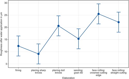
The results show that the roughness produced during the machining process depend on the machining method used (see ). The lowest roughness was achieved by planing with a sharp knife followed by fining. The highest roughness occurred in face milling, and this increased because of the rounded cutting edges.
Figure 9. Roughness after water application (13 g/m²) and re-drying (measured in the fiber direction).
The investigations show that the rougher surfaces that occur during face milling lead to higher bond strengths. The adjustment of the cutting geometry of the face milling cutter leads to a further improvement of the bonding quality. The tensile shear strength (bearing sequences: A1, A4, and A5) and the wood breakage percentage are shown in and (wood breakage percentage). The rougher surface leads to better penetration of the adhesive, thus resulting in improved adhesion. This issue is also referred to by Frihart and Konnerth in Niemz et al. (Citation2023). The trend is consistent with the empirical experience of adhesive producers that rougher surfaces lead to better adhesion. The research confirms that no general correlation exists between shear strength and wood failure rate (see e.g. Arnold et al. Citation2019).
Figure 10. Tensile shear strength after storage sequence A1, A4, and A5 as a function of the type of surface treatment.
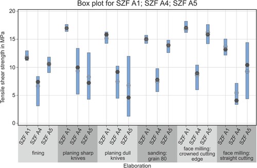
Table 2. Percentage of wood broken.
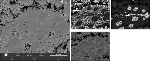
In the image captured using scanning electron microscopy (, left), a filling of the wood pores by the PUR adhesive is clearly visible. In addition, the right side of shows the distribution of the elements, O, C, and Si, in combination with EDX (scanning electron microscopy and energy dispersive X-ray spectroscopy), Hubalkova Citation2023. The adhesive distribution is clearly visible because approximately 5% of silicon dioxide is added as an additive, thus adjusting the rheological properties of the adhesive. The three-dimensional formation of the adhesive joint can be observed. The three-dimensional penetration of the adhesive into the pore structure of the wood (e.g. in the case of fibres lying slightly inclined to the wood surface, in the case of softwood penetration via the luminas of the fibers, see Suchsland (Citation1958), or the vessels in the case of hardwood (see work by) (Hass Citation2012, Hass et al. Citation2013, Paris et al. Citation2014, Jakes et al. Citation2019)) leads to increased anchorage of the adhesive with the wood when pores are openly accessible. Therefore, studies have been conducted on the modeling of adhesive joints by, Hammerquist and Nairn (Citation2018), Hass (Citation2012), Hass et al. (Citation2013), and Jakes et al. (Citation2019). Furthermore, modeling was also performed by e.g. Hammerquist and Nairn (Citation2018), Mendoza et al. (Citation2012), and Schwarzkopf et al. (Citation2016).
Figure 11. Adhesive joint Sample 2: Detail section 3 from – SE image left, BSE image right; Element distribution of O, C, and Si measured with EDX.
Some agreement on this finding was formulated in Frihart et al. (Citation2023), as follows:
Mechanical interlocking theory is certainly a common explanation, especially given the cellular nature of wood, but it is unclear how much strength this provides, especially when the applied force is perpendicular to the bond-line. A split open earlywood cell can allow adhesives to enter the lumen, given its diameter of 30–40 μm for softwood tracheids and 10–20 μm for hardwood fibers, but this is not necessarily true for the larger filler particles. On the other hand, latewood cells cleaved in the middle lamella are less likely to have much mechanical interlocking … .
In summary, wood is a complicated interplay of anatomical, physical and chemical effects. Increasing the roughness increases the surface area of the bonding surfaces. In addition, an additional mechanical interlocking of the adhesive in the part to be joined along the glue line is enabled. Further, the adhesive should penetrate the cavities of the wood structure and enter the imperfections caused by machining. Therefore, too high or too low viscosities of the adhesive (wetting and penetration behavior) reduce the size of the contact areas between the adhesive and the surfaces to be bonded. The basic relationships of the end-ringing of adhesives into the wood structure are described (Mendoza et al. Citation2012) using the properties of the adhesive (viscosity and surface tension), wood structure, and processing parameters. For PUR adhesives, curing limits adhesive penetration. The penetration depths determined for beech are approximately 300 µm. The deformation of the wood structure can lead to a reduction in the penetration depth of the adhesive, thus affecting the bonding strength. These deformations are reduced during subsequent finishing and sanding. Removal of the plastically deformed deformation zone improves the strength of the bonded joint. This can be observed in the comparison of finished and ground test specimens (bearing sequence A5). Owing to the deeper penetration during grinding, complete removal of the deformation zone occurs; however, during finishing, approximately 50% of the deformed areas are not removed. In face milling, as cell deformation is almost completely avoided, face milling in combination with the slightly increased roughness leads to an optimized result. In addition, the effect of surface fibrillation during grinding and face milling described by Hernandez et al. (Citation2014) supports this effect.
Mechanically, the irregularities associated with roughness are also suitable for inhibiting the growth of cracks, eventually increasing the bond strength.
However, when a limit value of roughness is exceeded, these positive effects cannot be realized as the distance between the surfaces to be bonded increases locally.
In the concretization of the model of bonding developed by Mara, it can be assumed that elastic and plastic deformations and fractures occur below the cutting edge in the wood structure because of the milling process (see e.g. Fischer et al. Citation1980, Rehm Citation2002, Gottloeber Citation2014). During finishing and grinding, these zones are (at least partially) removed so that the substrate largely regains its original strength. Cell deformation is also avoided by the design of the cutting edges during face milling. The combination of a roughness that improves adhesion and minimized deformation of the wood cells under the cutting edge provides the best possible result under these conditions.
5. Summary and conclusions
The highest tensile shear strength as well as the highest wood breakage percentage in bearing sequences A1 and A4 is achieved via face milling.
The tensile shear strength depends on the machining process, which determines the change of the wood structure in volume, roughness, and the wettable surface.
An improvement of the tensile shear strength can be achieved by rounded cutting edges.
The assumed cause of the reduction in shear strength due to microstructural damage under the cutting edge has yet to be experimentally proven.
Systematic investigations on cutting edge optimization and bonding quality as well as on the damage to the wood structure under the cutting edge during face milling indicate potential for further improvement. Further optimization is possible if the rake angles are increased from the current 0° to approximately 15°.
Especially for hardwoods and woods that are difficult to bond, investigation on primers is necessary.
In future work, Digital Image Correlation and/or Micro-CT should be used to understand the failure mechanisms.
Acknowledgments
The authors would like to thank Mr. Martin Schallhammer, B.Eng. for his assistance in the preparation of the drawings and Mr. Dipl.-Ing. Arkadiusz Bernaczyk for methodical hints during the test specimen production.
Disclosure statement
No potential conflict of interest was reported by the author(s).
Additional information
Funding
Notes
1 Dimethylformamide.
2 Hydroxymethylated resorcinol.
3 Polymeric diphenylmethane diisocyanate.
4 Atomic/scanning force microscope.
5 Digital image correlation.
References
- Ammann, S., 2015. Mechanical performance of glue joints in structural hardwood elements. Thesis (PhD). Zürich: ETH Zürich.
- Ammann, S., et al., 2016. Quality assessment of glued ash wood for construction engineering. European Journal of Wood and Wood Products, 74, 67–74.
- Ammann, S., and Niemz, P., 2015. Mixed-mode fracture toughness of bond lines of PRF and PUR adhesives in European beech wood. Holzforschung, 69 (4), 415–421.
- Arnold, M., et al., 2019. Qualitätskontrolle der Flächenverklebung bei Brettschichtholz aus Laubholz, WHFF-Projekt Nr. 2017.18 Wissenschaftlicher Schlussbericht, Empa, Dübendorf, September 2019.
- Bockel, S., et al., 2019. The role of wood extractives in structural hardwood bonding and their influence on different adhesive systems. International Journal of Adhesion and Adhesives, 91, 43–53.
- Bockel, S., 2020. Structural bonding of European beech wood (Fagus sylvatica L.) with polyurethane adhesives. Thesis (PhD). Wien: Universität für Bodenkultur.
- Boeger, T., Sanchev-Ferrer, A., and Richter, K., 2022. Hydroxymethylated resorcinol (HMR) primer to improve the performance of wood-adhesive bonds – a review. International Journal of Adhesion and Adhesives, 113, 1-15.
- DIN 4776, n.d. DIN 4776 Kenngrößen RK, RPK, RKV, Mr1, Mr2 zur Beschreibung des Materialanteiles im Rauheitsprofil. Berlin, Köln: Beuth-Verlag.
- DIN 8589-3, Fertigungsverfahren Spanen, Teil 3: Fräsen; Einordnung, Unterteilung, Begriffe. Berlin, Köln: Beuth-Verlag.
- Ettelt, B., 1987. Sägen, fräsen, hobeln, bohren.. Stuttgart: DRW Verlag.
- Fischer, R., 1996. Die mechanische Holzbearbeitung - Überlegungen und Experimente zur theoretischen Grundlage der mechanischen Holzbearbeitung. HOB Die Holzbearbeitung, 43 (6), 65–74.
- Fischer, R., Knüpfer, W., and Regensburger, K., 1980. Orientierende versuche zur deformation beim schneiden von holz. Holztechnologie, 21, 49–54.
- Frihart, C., et al., 2023. Chapt. 14 - Joining and reassembling of wood. 1. Auflage ed. Cham: Springer Nature.
- Gottloeber, C., 2014. Zerspanung von holz und holzwerkstoffen: grundlagen-systematik-modellierung-prozessgestaltung. Leipzig: Fachbuchverlag Leipzig im Carl-Hanser Verlag.
- Grüll, G., et al., 2016. Planing quality of glulam lamellae and its impact on bonding quality and fracture surface characteristics. Wien: TU Wien.
- Habenicht, G., 2017. Kleben – erfolgreich und fehlerfrei. 7th ed. Wiesbaden: Vieweg.
- Hammerquist, C., and Nairn, J., 2018. Numerical simulation of pressure-driven adhesive penetration into realistic wood structures. Wood Science and Technology, 52, 1271–1288.
- Hänsel, A., et al., 2022. Selected previous findings on the factors influencing the gluing quality of solid wood products in timber construction and possible developments: a review. Wood Material Science & Engineering, 17 (3), 230–241.
- Hass, P., 2012. Penetration behavior of adhesives into solid wood and micromechanics of the bondline. Thesis (PhD). Zürich: ETH Zürich.
- Hass, P., Wittel, F., and Niemz, P., 2013. Generic failure mechanisms in adhesive bonds. hfsg, 67, 207–215.
- Heisel, U., and Tröger, J., 1991. Betrachtungen zum Stirnplanfräsen. HOB, 11, 18–24.
- Heisel, U., and Tröger, J., 1993. Qualitativ hochwertige Oberflächen durch Stirnplanfräsen. HOB, 40 (5), 80–88.
- Heisel, U., Tröger, J., and Lang, M., 1991a. Untersuchung des Planfräsens am Beispiel beschichteter Möbelteile. Teil 3. HOB Die Holzbearbeitung, 44 (6), 39–44.
- Heisel, U., Tröger, J., and Lang, M., 1991b. Untersuchungen des Planfräsens am Beispiel beschichteter Möbelbauteile Teil 1. HOB Die Holzbearbeitung, 43 (11), 48–52.
- Hernandez, R. (2014). Effects of cutting parameters on cutting forces and surface quality. European Journal of Wood and Wood Products, 72, 107–116.
- Hubalkova, J., 2023. Auswertungsbericht – Untersuchung der Fügestelle von Holzproben, Freiberg: Bergakademie Freiberg; Institut für Keramik und Feuerfest Werkstoffe (01/2023).
- Jakes, J., et al., 2019. X-ray methods to observe and quantify adhesive penetration into wood. Journal of Materials Science, 78, 705–718.
- Kläusler, O., 2014. Improvement of on component polyurethane bonded wooden joints under wet conditions. Thesis (PhD). Zürich: ETH Zürich.
- Kläusler, O., et al., 2014. Influence on wood machining on tensile shear strength and wood failure percentage of one-component polyuerthane bonded wooden joints after wetting. International Wood Products Journal, 5, 18–26. doi:10.1179/2042645313Y.0000000039.
- Knorz, M., 2012. Verklebung von Buche und Esche für tragende Holzbauteile. Garmisch Parten Kirchen, Vortrag, 18. Internationales Holzbau-Forum 2012.
- Kuenniger, T., Fischer, A., and Richter, K., 2006. Water soluble larch extractive: impact on 1p-Pur wood bonds. Zvolen: TU Zvolen.
- Luciana, A., et al., 2021. Alternative Baumarten im Klimawandel. Eine Stoffsammlung. Artensteckbrief 2.0. Freiburg: Forstliche Forschungs- und Versuchsanstalt Baden-Württemberg.
- Mendoza, M., et al., 2012. Adhesive penetration of hardwood: a generic penetration model. Wood Science and Technology, 46, 529–549.
- Moanda, D., Lehmann, M., and Niemz, P., 2022. Investigation of the impact of micro-structuring on the bonding performance of beechwood (Fagus Sylvatica L.). Forests, 13(113), 2–18.
- Neusser, H., and Krames, U., 1971. Die Oberflächengestalt von Holzspanplatten-Ihre Erfassung und Schönheitswirkung. Holz als Roh und Werkstoff, 29, 103–118. doi:10.1007/BF02615328.
- Niemz, P., 2022. Rissbildung bei BSH und BSP in Innenräumen. Holz. Zentralblatt. Nummer, 26, 427–429.
- Niemz, P. and Dunky, M., 2023a. Chapter 22: Biobased adhesives: sources, characteristics and applications. In: P. Niemz and M. Dunky, eds. Bonding of solid wood-based materials. Beverly, MA: Scrivener Publishing LLC.
- Niemz, P. and Dunky, M., 2023b. Chapter 23: Bonding of solid woodbased materials for timber construction. In: K. Mittal and M. Dunky, eds. Biobased Adhesives (pp. 660–663). Beverly, MA: Scrivener Publishing.
- Niemz, P., and Sonderegger, W., 2021. Holzphysik: Physik des Holzes und der Holzwerkstoffe. 2nd ed. München: Carl Hanser Verlag.
- Niemz, P., Teischinger, A., and Sandberg, D., 2023. Springer handbook of wood science and technology. 1st ed. Heidelberg: Springer.
- Paris, J., et al., 2014. Phenol formaldehyde adhesives formulated for advanced X-ray imaging in wood-composite bondlines. Journal of Materials Science, 49, 580–591. doi:10.1007/s10853-013-7738-2.
- Rehm, K., 2002. Untersuchungen zur Modellierung des Qualitätsbildungsmechanismus beim Fräsen von Holz unter Berücksichtigung der Mehrachsbearbeitung. Thesis (PhD). Dresden: TU Dresden.
- Riegel, A., 1997. Gefügeschädigungen durch spanende Bearbeitung- Stand der Erkenntnisse und mögliche Messmethoden. Holz als Roh- und Werkstoff, 36, 111–117. doi:10.1007/BF02990527.
- Ritar, A., 2002a. Exzellente oberflächen mit systemen rotoles, Hoče, Slovenija.: Forschungs- Und Entwicklungszentrum Für Maschinenbau Und Holzwirtschaft - Lestro Ledinek.
- Ritar, A., 2002b. How to set up the criteria for environmental controlled developing strategy in timber industry. Thesis (PhD). University of Ljubljana. Ljubljana: s.n.
- Ritar, V., 2002c. How to set up the criteria for environmental controlled developing strategy in timber industry. Thesis (PhD). University Ljubljana.
- Schwarzkopf, M., et al., 2016. Integrating optical measurement and modelling for quantitative analysis of the micromechanical load transfer in the wood-adhesive bond interphase. International Wood Products Journal, 7 (4), 231–234.
- Stewart, H., 1980. Some surface defects and problems related to wood moisture content. Wood and Fiber, 3, 175–182.
- Stewart, H.A., 1984. Result force and surface quality from some facemilling variables. Forest Prod. Journal, 19 (5), 21–24.
- Stewart, H.A., and Crist, J.B., 1982. Sem examination of surface damage PF wood after abrasive knife planing. Wood Science, 14, 106–109.
- Suchsland, O., 1958. Über das Eindringen des Leimes bei der Holzleimung und die Bedeutung der Eindringtiefe auf die Fugenfestigkeit. Holz als Roh- und Werkstoff, 16, 101–108. doi:10.1007/BF02615415.
- Tröger, J., 1990. Zum Einfluss des Neigungswinkels beim Umfangs- und Stirnfräsverfahren. HOB Die Holz-bearbeitung, 37 (6), 34–43.
- Tröger, J., and Schneider, M., 2015. Grundlagen und verfahren der Holzbearbeitung-Lehrbuch für das Bachelorstudium an Berufsakademien und Dualen Hochschulen. (Hrsg. Hänsel, A.; H.-P. Linde). Berlin: Logos Verlag.
- Westkämper, E., and Riegel, A., 1993a. Qualitätskriterien für feingehobelte Holzoberflächen. Holz als Roh- und Werkstoff, 51, 27–30.
- Westkämper, E., and Riegel, A., 1993b. Qualitätskriterien für geschliffene Massivholzoberflächen. Holz als Roh- und Werkstoff, 51, 121–125.
- Westkämper, U., and Schadoffsky, O., 1995a. Oberflächentopographie von Massivholz, Teil 1. HOB Die Holzbearbeitung HOB, 48 (3), 74–78.
- Westkämper, E., and Schadoffsky, O., 1995b. Oberflächentopographie von Massivholz, Teil 2. HOB Die Holzbearbeitung, 48 (4), 50–55.
- Zeppenfeld, G., and Grunwald, D., 2005. Klebstoffe für die Holz-und Möbelindustrie. 2nd ed. Stuttgart: DRW Verlag Weinbrenner & Co. KG.