?Mathematical formulae have been encoded as MathML and are displayed in this HTML version using MathJax in order to improve their display. Uncheck the box to turn MathJax off. This feature requires Javascript. Click on a formula to zoom.
ABSTRACT
Wood branches subjected to bending develop reaction wood to accommodate both tensile and compressive stresses. For softwood, such as Norway spruce and Scots pine, compression wood (CW) develops in the lower parts, while opposite wood (OW) develops on the upper parts of the branch. It is likely that the ratio of CW to OW is optimised for mechanical load bearing by nature. This hypothesis was tested with an analytical beam model using experimental data of stiffness and strength of CW and OW at CW fractions from 0 to 100%. It was found that there is indeed a maximum bending moment capacity around 35% CW, like literature values of CW content in softwood branches. For all compositions, compressive or tensile strength of OW was governing the behaviour.
1. Introduction
Evolution of trees has resulted in a variety of wood that are optimised for carrying load in different ways. Despite being composed of only a few key polymer components (cellulose, hemicellulose and lignin) deposited in the walls of elongated cells, trees are able to adapt to different environmental conditions and stresses acting upon it during growth leading to a wide variation in properties. The most notably differences are found in mechanical properties such as stiffness and strength (Dinwoodie Citation2017). At the cellular level, cell shape and thickness of cell walls may vary substantially. On the cell wall level, the stiff and strong cellulose microfibrils are aligned and embedded in a softer matrix of hemicellulose and lignin, and one way to adapt mechanical properties is to adjust the microfibril angle, i.e. the angle between the microfibril direction and the longitudinal direction of the cell.
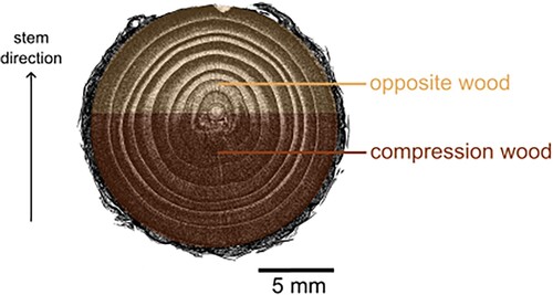
Branches are particularly adapted to support bending moments using an appropriate combination of wood with different mechanical properties just like manufactured composite components. Reaction wood is formed in branches to improve the load carrying capability and to account for high stresses caused by gravity, wind and snow load. In coniferous wood (softwood), the reaction wood is called compression wood (CW). Compression wood is formed on the lower side of the branch, i.e. the compressive side, whereas the wood on the opposite side of the branch consists of so called opposite wood (OW). Timell (Citation1986) and Donaldson and Singh (Citation2016). It is known that CW exhibits higher density, higher longitudinal shrinkage upon drying, lower longitudinal stiffness but comparable values of elastic limit (Timell Citation1986). A typical cross section of a softwood branch from a μCT scan is shown in , where the CW on the lower side is identified as darker and more dense.
Figure 1. Cross-section view of a branch of Norway spruce with compression wood and opposite wood taken by μCT scanning. The arrow showing the stem direction indicates the growth direction of the main stem of the tree.
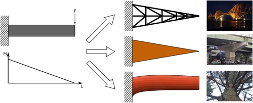
From a bio-mimetic point of view, it is of interest to investigate how CW and OW contribute to the load carrying capacity of softwood branches considering the branch as a structural composite. The understanding of mechanisms that govern its mechanical properties can generate ideas for improved design of engineered composite materials and components carrying significant moment forces, e.g. T-joints (Burns et al. Citation2012), rotor blades in wind turbines (Lund and Johansen Citation2008) and helicopters (Suresh et al. Citation2007). Moment-carrying cantilever beam-like components are often designed with tapered cross-sections or structural frameworks, whereas beams in nature, i.e. softwood branches, mainly make use of material gradients in their cross sections. Although the manufacturing of components composed of different materials is more difficult and costly than for uniform materials, using knowledgeable material combinations can lead to lighter and more slender designs. A schematic illustration of comparable structures is presented in .
Figure 2. Schematic illustration of beam design concepts in engineering and in nature, demonstrated by a softwood beam.
Although sophisticated computational tools such as the finite element method are readily available also for complex structures, analytical models are still important and ubiquitously used in engineering at a pre-design stage to make an initial investigation of complex phenomena before developing detailed numerical models. This approach is time efficient and allows for intellectual and strategic decisions. Therefore, the present study provides a systematic investigation of the elastic bending capacity of softwood branches based on an analytical composite Euler–Bernoulli beam model under the assumption that the branch is loaded within its elastic region. This analytical model accounts for the cross-sectional shape, proportions of OW and CW as well as their respective material properties. The effect of different material property combinations on maximum allowed bending moment can thereby easily be retrieved.
The material properties of importance used as input for the proposed model are elastic moduli of CW and OW () in longitudinal direction and maximum allowed normal stress (taken as strength values) of CW and OW in both tension and compression (
,
,
and
). Experimental measurements of these values are rare and show a large variation ; however, some characteristics are known from literature (experimental data).
| (1) |
| ||||
| (2) | Experimental data of | ||||
In this study, the choice of material properties is somewhat arbitrary, but within order of magnitude that is likely to be valid for wood in softwood branches. However, it is important to keep in mind that these values are mainly meant to demonstrate the ability of this particular model to predict in which part (CW/OW) the branch will reach its elastic limit and also under which type of load condition (tension/compression).
2. Theory and methods
2.1. Beam model
Softwood branches composed of both OW and CW are modelled using Euler–Bernoulli beam theory. This model builds on the kinematic assumptions that the cross-section is infinitely rigid in its own plane, remains plane after beam deformation, and remains normal to the deformed axis of the beam. This allows for a linear elastic description of long, slender and straight beams with a simple cross section subjected to lateral loads that undergo small deformations neglecting the effect of shear. Since, in this paper, the main interest is to perform an initial investigation of the effect changes in the ratio between OW and CW have on the bending capacity of softwood branches, a linear elastic model is well suited. Using the Euler–Bernoulli beam theory, the maximum moment given for a governing stress state can be given by:
(1)
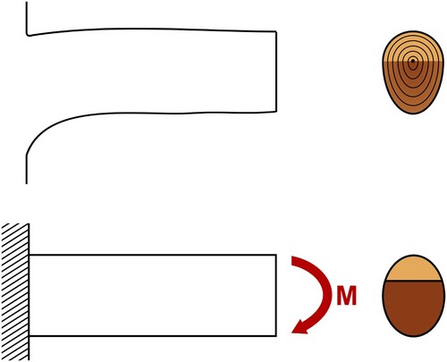
(1) where, k indicates either CW or OW and i indicates the governing stress state that can be either tension, t, or compression, c. In this study, the normal stress σ is taken as the maximum bending strength due to the absence of detailed elastic stress-strain information and I is the second moment of inertia of the beam. The beam is loaded in pure bending, as shown in .
Figure 3. Comparison of a branch and the Euler–Bernoulli beam model.
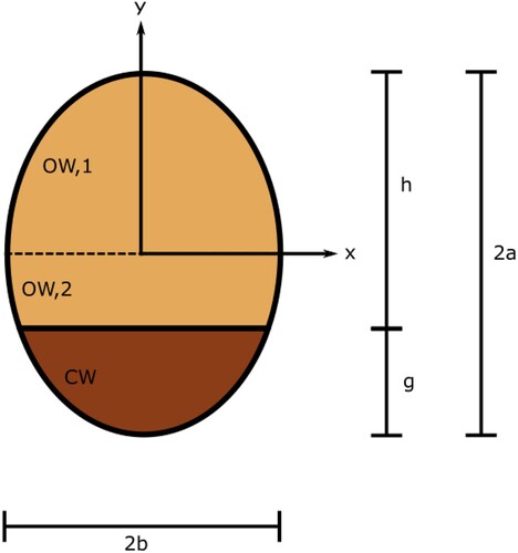
The mechanical load on branches is found to incite growth from a circular to an elliptical cross section (Telewski Citation2016). A beam model previously used for branches with circular cross sections of uniform material (Cannell and Morgan Citation1989) is here extended to a more realistic elliptical bi-material cross section. The softwood branches in this study are regarded as beams with uniform cross sections, which indicates a long horizontal segment with two identical shapes facing each other (Achim et al. Citation2006). This is a simplification from reality, where the cross section generally varies along the branch (Archer and Wilson Citation1973). The present beam model assumes an elliptical cross-section of the branch with two distinct subsections composed of CW and OW respectively as illustrated in . The cross-section is described by the following mathematical equation of an ellipse:
(2)
(2) where a and b are the semi-axes in the y and x directions, respectively. Although a gradual transition from severe CW to OW has been observed (Cannell and Morgan Citation1989), this model simplifies reality by considering two distinct tissues, namely CW and OW. The upper part of the beam corresponds to OW and the lower part to CW. In the present study, the area ratio for the two materials was varied between the extreme cases of 0 and 100% CW, to cover the entire range from no-CW to an all-CW material. Somewhere between these two extremes, an optimum should be expected. Euler–Bernoulli beam theory is applicable to homogeneous cross-section's with simple geometries. To be able to model a composite beam, the effective area of the compression wood is transformed using the ratio, n, between the elastic moduli of compression wood,
, and opposite wood,
:
(3)
(3) This leads to a transformed effective area of compression wood as follows:
(4)
(4) A full description of the beam model and how the area of CW and OW is determined can be found in the Appendix.
The mechanical properties corresponding to OW and CW used in the present study and as found in literature (Timell Citation1986, Burgert and Jungnikl Citation2004, Dinwoodie Citation2017, Li et al. Citation2021) are presented in . The elastic moduli were determined by tensile testing of tissue slices from branches in green condition rather than testing solid dried wood specimens from the stem (Burgert and Jungnikl Citation2004). Hence, the elastic moduli are lower than that of Norway spruce typically listed in the literature. The governing stress states, σ, is, for the sake of simplicity and in lack of detailed stress-strain data in the elastic region of wood branches, assumed to be the tensile limit values presented in . It should be noticed that the stress-strain behaviour of Norway spruce is different in tension and compression, and also different for CW and OW.
Table 1. Mechanical properties of compression and opposite wood in Norway spruce.
The beam model is versatile. Its general characteristics such as dimensions, cross-section aspect ratio, relative amount of CW, elastic and strength properties of the wood materials can be varied indefinitely to account for any wood species. Hardwoods can also be modelled, where the reaction wood is formed as tension wood on the upper side of branches (e.g. Donaldson and Singh Citation2016).
Any residual stresses are neglected in this work. Such stresses could be estimated by cutting operations, after which strain is released. Leaning stems including compression wood show this phenomenon (Gril et al. Citation2017), whereas the spring back is much smaller when pruning and limbing spruce branches (Morgan Citation2011). Recently, Van Rooij et al. (Citation2023), investigated the effect of residual stresses and eccentricity of branches on their posture. Their model showed that the largest residual stresses were found in the pith, i.e. far away from the upper and lower sides where the critical bending stresses are generated.
2.2. Maximum bending moment
In structural engineering, design of beams is typically based on their resistance to bending moment, e.g. in Eurocode. The expression used to describe the maximum bending moment, , in this study can be found in Equation (Equation1
(1)
(1) ). The maximum value depends on the material composition, geometry and mechanical properties of the constituents. The mechanical properties as found in and geometry are fixed in this study. The bending moment will be presented as normalised by the maximum bending moment when no CW is present, which makes the analysis independent of the branch geometry as long as it is elliptical.
(5)
(5) The normalised bending moment,
, is then determined as a function of CW content, being the parameter of higher interest in this context. The maximum moment is defined by the governing stress state, which occurs first, i.e. the one represented by the smallest moment:
(6)
(6) A more detailed description of this approach can be found in the Appendix.
3. Results and discussion
The main result from the model, from Equation (Equation6
(6)
(6) ), is presented followed by a more detailed analysis of the different governing stress states as well as a comparison between nature's design of branches and engineered structures.
3.1. Maximum bending moment
Calculations using the beam model with the proposed material parameters show that an increasing area fraction of CW in the branch allows it to be able to carry a higher maximum bending moment, as can be seen in . The maximum bending moment increases rapidly at area fractions of CW below 35% and remains thereafter at a high level of normalised moment (approximately 35% higher maximum moment than the no-CW branch) when between 35 and 75% CW. The knee point at around 35% CW arises from a transition in governing stress situations, as will be discussed in the next section. Increasing the area fraction of CW beyond 75% leads to a drastic decrease in maximum moment. Above 90% CW, the branch shows inferior properties compared to a branch with no-CW.
Figure 4. Maximum moment depending on area proportion of compression wood in a branch cross section as also schematically indicated above the graph; light colour corresponds to OW and dark colour to CW. The shaded area shows relative amounts of CW found in softwood branches (Low Citation1964, Harris Citation1977, Spicer and Gartner Citation1998, Li et al. Citation2014).
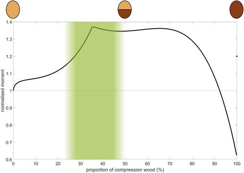
The shaded interval in refers to a span of measured relative CW contents in softwood branch cross-sections found in literature (Low Citation1964, Harris Citation1977, Spicer and Gartner Citation1998, Li et al. Citation2014), and ranges from 24% up to 50%. It can be noted that the estimated maximum bending moment occurs within this interval. The composition of CW/OW found in nature thus leads to the highest moment bearing capacity. Although there is a plateau of high maximum bending moment, it is preferable for the tree to develop as little CW as possible, and still achieve sufficient strengthening of the branch. The higher density of CW compared to OW (Gryc and Horáček Citation2008) implies that the growth of CW comes at a higher biological cost than that of the less dense OW. In addition to carrying load, the wood tissue has a function of transporting water and nutrients. Since the hydraulic conductivity is poorer in CW than OW (Mayr and Cochard Citation2003), there should not be too much CW at the expense of OW in any given cross section, in order to maintain an efficient hydraulic capacity. A relative CW content of around 35% at the beginning of the plateau in would then be preferable in the present case, since a high bending capacity is achieved without having to produce any unnecessary amount of CW.
3.2. Governing stress situations
In the optimal design of structural components composed of joint parts of different materials, neither part should be over-designed. The inefficient use of material that does not contribute to the overall load-carrying capacity of the component leads to an unnecessary cost. In this section, therefore, the governing stress state for each proportion of compression wood is analysed.
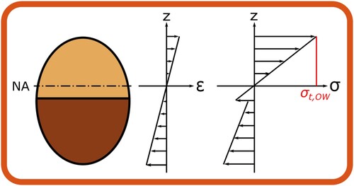
The ratio between OW and CW inside the cross section of a branch influences the stress distribution over the height of the branch. When the area fraction of CW is varied, it gives rise to different characteristic stress distributions as shown in and . The ratio of the highest stress and the strength for that particular material (CW or OW) and loading direction (compression or tension) can be determined based on the strength values compiled in . The highest ratio indicates the governing stress situation for a particular composition. For the given situation, two dominant stress situations were recognised:
High compressive stress in OW for lower fractions of CW
High tensile stress in OW for higher fractions of CW
Figure 5. Stress and strain profiles in beam bending of a branch with 25% CW.
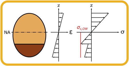
Figure 6. Stress and strain profiles in beam bending of a branch with 50% CW.
The governing stress situations are further illustrated in , where it can clearly be observed that the compressive stress limits in OW are reached first for fractions of CW lower than 35%, and that the limits of tension stress in OW occurs for fractions above 35%. In reality the transition from OW to CW is gradual from mild to severe CW (e.g. Donaldson et al. Citation2004), and not discontinuous with a knee-point at ∼ 35% of CW. A smooth transition in stress distribution is therefore expected in real wood branches, although the general trends in the predictions with an optimum in bending capacity are anticipated. A smooth transition in failure modes has been observed for mixed composite materials depending on the relative volume fractions of constituents (Kretsis Citation1987), where a positive synergy between constituents of different material properties is called a “hybrid effect”.
Figure 7. Moment corresponding to the governing stress states. Compressive governing stress state in OW (yellow), tensile governing stress state in OW (orange), compressive governing stress state in CW (blue) occur depending on the proportion of compression wood in the branch. The shaded area shows relative amount of CW found in softwood branches.
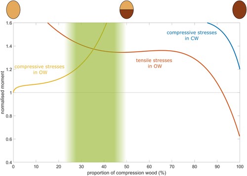
In the present case, the highest bending moment occurs at about 35% of CW, which is the point where governing stress state in CW and OW are reached simultaneously, i.e. neither of the beam layers is over-designed. The amount of compression wood found in softwood branches (Low Citation1964, Harris Citation1977, Spicer and Gartner Citation1998, Li et al. Citation2014) overlaps this transition point, as indicated by the shaded area in .
Next to the governing stress situations being high compressive and tensile stress in the OW part, a third hypothetical stress mechanism presents itself as the blue line in as high compressive stress in CW. This governing stress situation does not occur except for the all-CW case, as shown if as a dot where the proportion of CW is exactly 100%.
The model also readily shows where the location of the governing stress state at the cross-section is, as shown in and . The largest stresses occur intermediately far (at 25% CW) and far (at 50% CW) away from neutral axis. This is in consistent with observations by Müller et al. (Citation2006), that tissue damage and delaminations occur between outer annual rings in bending of Norway spruce branches, far away from the neutral axis where the largest stresses are found. However, it is important to remember that the proposed model only considers normal stress in the elastic region, while shear and plastic behaviour is not included. Also, breakage is a dynamic and instantaneous process, where a significant amount of elastic energy is suddenly released leading to secondary damage and failure modes.
3.3. Comparison to engineered structures
This section will return to the different means to increase the load-carrying capacity of beams illustrated schematically in . The results obtained with the beam model above highlight the possibility to increase the mechanical performance by a clever cross-sectional composition rather than increasing dimensions.
Simulations of bending of slender composite T-joints have illustrated how orientation of composite layers from the compressive to the tensile side can be controlled in a way to increase the bending capacity (Burns et al. Citation2012, Citation2015). It was found that a lay-up with fibres oriented more towards the direction of the protruding beam on the tensile side and fibres oriented transverse to this direction on the compressive side, resulted in significantly increased bending strength compared with baseline quasi-isotropic lay-up. This follows the same trend as for softwood branches where the microfibril angle is high for CW and low for OW (Timell Citation1986).
A classical example where the difference in compressive and tensile strength necessitates redesign of beams subjected to moments is the reinforcement of concrete. The brittleness of unreinforced concrete leads to a significantly lower strength in tension compared with the compressive case. This shortcoming can be overcome by reinforcing the beam with steel bars on the weaker tensile side of the beam. How to place these reinforcements is fundamental in the design of concrete structures (e.g. Chakrabarty Citation1992). For a cantilever beam-like structure, such as a balcony, the reinforcement is placed on the upper tensile side (Barros et al. Citation2022), just like tensile wood is formed on the upper tensile side of hardwood branches (Fisher and Stevenson Citation1981). In reinforced concrete, the steel bars are oriented in the tensile direction, similarly to orientation of the strong cellulose crystals in the gelatinous layers of tensile wood in hardwood branches.
For monolithic materials, such as metals, surface treatments are common on the tensile side of components to improve the tensile performance, especially in fatigue. Shot peening is one such method, which induces compressive residual stresses close to the surface (Hammersley et al. Citation2000). As can be noted, there are several examples of engineered materials which have been designed for improved performance in structures subjected to bending. With different materials (or residual stresses) on the tensile and compressive side, a higher moment capacity can be achieved while keeping the beam structure slender without having to resort to a higher cross section as shown in . Although a beam composed of several materials is more costly to manufacture and recycle, this option might be worthwhile to a larger extent than is commonly the practice today, given the significantly improved overall strength. As has been illustrated, softwood branches show how this strengthening mechanism can be used in nature, and may provide some incitement to use this possibility further in materials design.
4. Conclusions
An elastic composite beam model was applied to manifest the mechanical significance of the presence of both CW and OW in softwood branches. By using material parameters from literature and vary the CW/OW ratio, it was found that the optimal composition of a branch cross section is between 35 and 75% of CW with regard to maximum bending moment. Material properties of OW govern the critical stress situation, where compressive limit of OW is crucial at low fractions of CW, whereas tensile limit of OW governs the maximum bending moment at higher CW content.
The presented model is a simple way to elucidate the mechanical function of CW as an enhancer of bending moment strength in branches in living trees.
Disclosure statement
No potential conflict of interest was reported by the author(s).
References
- Achim A., Gardiner B., Leban J.-M., and Daquitaine R., 2006. Predicting the branching properties of Sitka spruce grown in Great Britain. New Zealand Journal of Forestry Science, 36, 246.
- Archer R.R., and Wilson B.F., Apr 1973. Mechanics of the compression wood response: II. On the location, action, and distribution of compression wood formation. Plant Physiology, 51 (4), 777–782.
- Barros J.A.O., Figueiredo F.P., Costa I.G., and Dourado F.N.F.M., Jan 2022. New type of CFRP reinforcement and technique for the flexural strengthening of RC balconies. Composite Structures, 280, 114899.
- Burgert I., and Jungnikl K., Jun 2004. Adaptive growth of gymnosperm branches-Ultrastructural and micromechanical examinations. Journal of Plant Growth Regulation, 23 (2), 76–82.
- Burns L.A., Mouritz A.P., Pook D., and Feih S., Feb 2012. Bio-inspired design of aerospace composite joints for improved damage tolerance. Composite Structures, 94 (3), 995–1004.
- Burns L., Mouritz A.P., Pook D., and Feih S., Feb 2015. Bio-inspired hierarchical design of composite T-joints with improved structural properties. Composites Part B: Engineering, 69, 222–231.
- Burns L., Mouritz A., Pook D., and Feih S., Nov 2012. Strength improvement to composite T-joints under bending through bio-inspired design. Composites Part A: Applied Science and Manufacturing, 43 (11), 1971–1980.
- Cannell M.G.R., and Morgan J., Sept 1989. Branch breakage under snow and ice loads. Tree Physiology, 5 (3), 307–317.
- Chakrabarty B.K., Feb 1992. Models for optimal design of reinforced concrete beams. Computers & Structures, 42 (3), 447–451.
- Dinwoodie J.M., Sept 2017. Timber: its nature and behaviour. 2nd ed. London: CRC Press.
- Donaldson L.A., Grace J., and Downes G.M., Jan 2004. Within-tree variation in anatomical properties of compression wood in radiata pine. IAWA Journal, 25 (3), 253–271.
- Donaldson L.A., and Singh A.P., 2016. Chapter 6 – Reaction wood. In: Y.S. Kim, R. Funada, and A.P. Singh, eds. Secondary xylem biology. Boston: Academic Press, 93–110.
- Fisher J.B., and Stevenson J.W., Mar 1981. Occurrence of reaction wood in branches of dicotyledons and its role in tree architecture. Botanical Gazette, 142 (1), 82–95.
- Gril J., Jullien D., Bardet S., and Yamamoto H., Oct 2017. Tree growth stress and related problems. Journal of Wood Science, 63 (5), 411–432.
- Gryc V., and Horáček P., Jan 2008. Variability in density of spruce (Picea abies [L.] Karst.) wood with the presence of reaction wood. Journal of Forest Science, 53 (3), 129–137.
- Hammersley G., Hackel L.A., and Harris F., Oct 2000. Surface prestressing to improve fatigue strength of components by laser shot peening. Optics and Lasers in Engineering, 34 (4), 327–337.
- Harris J.M., 1977. Shrinkage and density of radiata pine compression wood in relation to its anatomy and mode of formation. New Zealand Journal of Forestry Science, 7 (1), 16.
- Kretsis G., Jan 1987. A review of the tensile, compressive, flexural and shear properties of hybrid fibre-reinforced plastics. Composites, 18 (1), 13–23.
- Li X., Evans R., Gapare W., Yang X., and Wu H.X., Dec 2014. Characterizing compression wood formed in radiata pine branches. IAWA Journal, 35 (4), 385–394.
- Li Z., Zhan T., Eder M., Jiang J., Lyu J., and Cao J., Dec 2021. Comparative studies on wood structure and microtensile properties between compression and opposite wood fibers of Chinese fir plantation. Journal of Wood Science, 67 (1), 12.
- Low A.J., Jan 1964. A study of compression wood in Scots Pine (Pinus silvestris L.)1: with I plate. Forestry: An International Journal of Forest Research, 37 (2), 179–201.
- Lund E., and Johansen L.S., 2008. On buckling optimization of a wind turbine blade. In: Mechanical response of composites. Vol. 10. Dordrecht: Springer, 243–260.
- Mayr S., and Cochard H., 2003. A new method for vulnerability analysis of small xylem areas reveals that compression wood of Norway spruce has lower hydraulic safety than opposite wood. Plant, Cell & Environment, 26 (8), 1365–1371.
- Morgan K.O., 2011. The complete guide to pruning trees and bushes. Ocala, FL: The Atlantic Publishing Group.
- Müller U., Gindl W., and Jeronimidis G., Sept 2006. Biomechanics of a branch – stem junction in softwood. Trees, 20 (5), 643–648.
- Spicer R., and Gartner B.L., Nov 1998. Hydraulic properties of Douglas-fir (Pseudotsuga menziesii) branches and branch halves with reference to compression wood. Tree Physiology, 18 (11), 777–784.
- Suresh S., Sujit P., and Rao A., Dec 2007. Particle swarm optimization approach for multi-objective composite box-beam design. Composite Structures, 81 (4), 598–605.
- Telewski F.W., Jan 2016. Chapter 5 – Flexure wood: mechanical stress induced secondary xylem formation. In: Y.S. Kim, R. Funada, and A.P. Singh, eds. Secondary xylem biology. Boston: Academic Press, 73–91.
- Timell T.E., 1986. Compression wood in gymnosperms. 1st ed. Berlin: Springer.
- Van Rooij A., Badel E., Barczi J.-F., Caraglio Y., Almeras T., and Gril J., Aug 2023. Modelling the growth stress in tree branches: Eccentric growth vs. reaction wood. Peer Community Journal, 3, e78.
Appendix. Beam model of a branch containing compression wood
Euler–Bernoulli beam theory is used. An elliptical cross-section is assumed, defined in Cartesian coordinates by
(A1)
(A1) where a and b are the semi-axes in the y and x directions, respectively.
We first consider the case when the compression wood proportion is lower than 50% with a>0, b>0, h>0, g>0, h>a, g<a. The area of the compression wood is determined as follows:
(A2)
(A2) The area of the opposite wood
is determined from of the areas below and above the mid-plane, where the origin of the coordinate system is located, namely
(A3)
(A3) and
(A4)
(A4) The modular ratio n for the bimaterial composite beam with two distinct elastic moduli is defined as
(A5)
(A5) Hence, the transformed effective area of the area of compression wood is
(A6)
(A6) Only the minor axis then need to be transformed
to obtain a valid cross-section
(A7)
(A7) Thereby, the centers of gravity of each section are defined as:
(A8)
(A8)
(A9)
(A9)
(A10)
(A10) The center of gravity of the whole composite cross-section
is determined by
(A11)
(A11)
The second moments of area of each section with respect to its center of gravity are defined by
(A12)
(A12)
(A13)
(A13)
(A14)
(A14) According to the parallel axis theorem, the second moment of inertia for the composite cross-section is
(A15)
(A15) where
is the distance between the center of the gravity of each section and the center of gravity of the entire composite cross-section
(A16)
(A16) In order to determine the maximum moment before failure, the stress is assumed to reach the strength value at the following positions:
(A17)
(A17)
(A18)
(A18)
(A19)
(A19) The maximum moment for the three governing stress situations are:
(A20)
(A20)
(A21)
(A21)
(A22)
(A22) The maximum moment is the defined by the governing stress state which occurs first, i.e. the one represented by the smallest moment:
(A23)
(A23) which can be normalised with the maximum moment in the case there is no CW:
(A24)
(A24)
Figure A1. Idealized elliptical cross-section containing both OW and CW.