Abstract
This paper presents an evaluation of the behaviour of geogrid-reinforced railway ballast. Experimental large box pull-out tests were conducted to examine the key parameters influencing the interaction between ballast and the geogrid. The experimental results demonstrated that the triaxial geogrid outperforms the biaxial geogrid and the geogrid aperture size is more influential than rib profile and junction profile. The discrete element method (DEM) has then been used to model the interaction between ballast and geogrid by simulating large box pull-out tests and comparing with experimental results. The DEM simulation results have been shown to provide good predictions of the pull-out resistance and reveal the distribution of contact forces in the geogrid-reinforced ballast system. Therefore, the calibrated geogrid model and the use of clumps to model ballast particles hold much promise for investigating the interaction between geogrids and ballast and therefore optimising performance.
1. Instruction
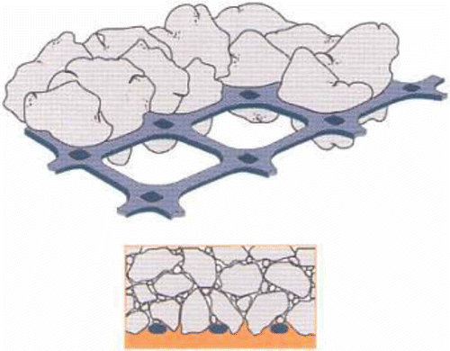
Geogrids have been successfully used for the reinforcement of railway track over the past decades. A geogrid can be placed within the ballast layer to reduce ballast deformation and extend the maintenance cycle by a factor of about 3.0, or at the top of the subgrade to increase the bearing capacity of the track foundation (Tensar Citation2009). The conventional biaxial geogrids are produced with high stiffness in longitudinal and transverse directions with square apertures to suit the ballast grading. The triaxial geogrid has evolved which involves a change in grid aperture shape from rectangular to a triangular one which is a more stable geometric shape for structural efficiency (Tensar Citation2010). The large box pull-out test is considered to be suitable means of investigating the fundamental mechanics of ballast/geogrid interactions, as shown in
Figure 1. Interlocking between particles and geogrid (Tensar Citation2009).
Brown et al. (Citation2007) carried out a series of experiments using biaxial geogrids to investigate key parameters that affect its performance. They found that the optimum aperture size was 60--80 mm for ballast particles approximately 50 mm in size. However, the optimum geometry of triaxial geogrid to provide maximum interlock is not known. In addition, the other key parameters that influence geogrid reinforcement of ballast such as rib stiffness, rib cross-sectional profile and junction strength still need to be investigated. The discrete element method (DEM) (Cundall and Strack Citation1979) allows monitoring of the evolution of the inter-particle contact forces and displacement of particles; this cannot be done in the laboratory. Zhang et al. (Citation2008) presented DEM simulations of geogrid pull-out behaviour using PFC2D and compared it with experimental results and it showed some agreement. The use of PFC3D to model ballast particles and introduce interlock using clumps have also been described (Lim and McDowell Citation2005, Lu and McDowell Citation2007). McDowell et al. (Citation2006) involved application of DEM for modelling of both ballast and the biaxial geogrid, together with small box pull-out experiments to validate the simulation results. They found that the optimum ratio between geogrid aperture size and aggregate size should be around 1.4.
This paper firstly presents large box pull-out experiments with different types of biaxial and triaxial geogrid. These experiments aim to compare the performance of biaxial and triaxial geogrids and also investigate the key parameters that influence geogrid reinforcement. For the DEM simulations, a ballast particle modelled using a two-ball clump and a two-layer geogrid model using parallel bonded balls are presented. The micro-parameters of the geogrid model are calibrated in terms of stiffness and strength by performing tensile and rotational tests on the geogrid. The geogrid-reinforced system is then modelled in simulated large box pull-out tests and compared with experimental results, in order to obtain a valuable insight into the interlocking mechanism of geogrid-reinforced ballast.
2. Large box pull-out test
2.1 Test description
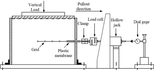
A typical pull-out test performed by Kwan (Citation2006) was conducted in a small wooden box with dimensions of 200 mm wide × 300 mm long × 400 mm deep. However, interpretation of unrepeatable pull-out test results continues to be a difficult task owing to the boundary condition of small box and fewer apertures being tested. Moreover, Palmeira and Milligan (Citation1989) found that the internal friction angle between the soil and reinforcement could be severely overestimated because of friction on the internal front wall of the box in small scale tests. They recommended lubricating the front face and increasing the scale of the test. Hence, a larger box measuring 400 mm wide × 600 mm long × 400 mm deep which is four times larger than the small box was used in these experimental pull-out tests. shows the schematic diagram of the large-box pull out test. The box is filled with 140 kg graded ballast with a geogrid layer placed at mid-depth protruding out of the box through a slot in right-hand wall of the box. A thin plastic membrane, placed on either side of the grid, is used to cover the aperture through the opening of the slot to prevent the grid trapping aggregate between the grid nodes and the slot. It has considerably improved the reliability and repeatability of the test results. A load cell with a 3 kN capacity is used for measuring the pull-out force applied by the hydraulic jack, which pulls the geogrid out at an approximately constant rate. A dial gauge measures displacement intervals over pull-out distance of 50 mm.
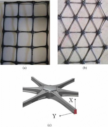
In these experiments, the ballast mean size is approximately 40 mm, and the initial density is approximately 1458 kg/m3. The polymer geogrids of biaxial and triaxial types are shown in
2.2 Experimental results
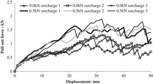
The pull-out tests were conducted using surcharges of 0 and 0.5 kN for six types of geogrids respectively. A summary of all the tested geogrids is given in . Each type of pull-out test was performed three times to ensure repeatability. shows the repeated tested results for biaxial geogrid SSLA30 in terms of pull-out force as a function of pull-out displacement for surcharges of 0 and 0.5 kN. Good repeatability was observed. In order to evaluate these geogrid performances effectively, the average peak forces for each geogrid are compared as shown in It is clear that a higher average peak force was recorded as the geogrid aperture size increased, thus confirming that the aperture size of both biaxial and triaxial geogrids have a direct influence on the particle-geogrid interlock and therefore pull-out resistance. Moreover, the aperture size of SS40 is 32 mm which is too small to allow proper interlock with ballast.
Table 1. Tested geogrids
Figure 5. Influence of aperture shape and size on pull-out resistance: (a) without surcharge; (b) under 0.5 kN surcharge.
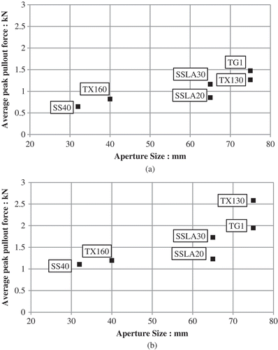
TG1 geogrid has the same aperture shape and size as TX130 geogrid but a different cross-section shape of the ribs as detailed in . Taking the plane of the geogrid to be horizontal, TX130 has a horizontal rectangular cross-section and TG1 has a vertical rectangular cross-section, which makes the ribs of TG1 stiffer in bending in the vertical plane, but less stiff in bending in the horizontal plane, due to the reduced second moment of area about the axis of bending. The relative performance, in , shows that TG1 offers potentially better interlock capabilities at 0 kN surcharge but less interlock at 0.5 kN surcharge. This is likely to be attributed to the different bending stiffness of the ribs, as shown in Under increasing surcharge and interlock, the ribs deform more easily in the plane of the geogrid (the Y direction) with a resulting reduced pull-out resistance.
The other issue which may be explained by a rib profile effect is the significantly better performance of SSLA30 geogrid compared with SSLA20. SSLA20 and SSLA30 have the same square aperture size of 65 mm, but the ribs of SSLA30 are thicker than those of SSLA20 (see ), which give better ballast confinement. Comparing SS40 and SSLA20, it is evident that SSLA20 (aperture size of 65 mm, rib tensile strength of 20 kN/m) gave greater average interlock with the ballast particles than SS40 (aperture size of 32 mm, rib tensile strength of 40 kN/m) and a higher peak force. This indicated the aperture size is dominant in interlocking compared with the tensile strength of ribs.
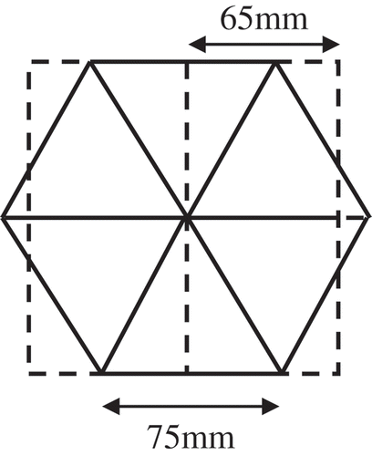
The pull-out resistance of geogrid includes two components: the interface shear resistance that takes place along the longitudinal ribs (and to a lesser extent along the transverse ribs) and the bearing resistance that develops against the front of transverse ribs (Koerner et al. Citation1989). As shown in , TG1, Tx130, SSLA20 and SSLA30 have approximately the same area of coverage for a single reinforcing unit apart from the difference in aperture shape. shows that the triaxial geogrids (TX130, TG1) outperform the biaxial geogrids (SSLA20 and SSLA30) especially under the 0.5 kN surcharge. This improvement could be explained by the geometry in For the biaxial geogrid, most pull-out resistance comes from the bearing on the transverse ribs. For the triaxial geogrid, non-transverse ribs carry load in both the longitudinal and transverse directions giving extra resistance. Therefore, triaxial geogrids can provide more pull-out resistance than biaxial geogrids for the same geogrid area. Besides, biaxial geogrids have tensile stiffness predominantly in two directions. Triaxial geogrids have three principal directions of stiffness, which is further enhanced by the triangular geometry providing stiffness through 360° (Tensar Citation2010).
3. Discrete element modelling (DEM) of large box pull-out test
3.1 Discrete element modelling studies
The discrete element method has been used for simulating complex soil/aggregate geogrid interaction (Konietzky et al. Citation2004, McDowell et al. 2006, Zhang et al. Citation2007, 2008). This numerical simulation approach is fully capable of modelling the interaction of ballast particle and the geogrid by accounting for the aggregate particle shape, reproducing the actual geometry of geogrid and assigning properly particles and geogrids properties. In this methodology, force displacement laws for different element bonding conditions and the laws of motion govern the movement and contacts of each element (ball and wall).
Recent work by Konietzky et al. (Citation2004) and McDowell et al. (2006) focused on aggregate and geogrid interactions and modelling confinement effects. The findings of DEM studies covered interaction between geogrids and surrounding soil/aggregate in both triaxial and small box pull-out tests, contact force distributions, deformations and particle rearrangements. The simulations demonstrated the development of strong contact forces in the vicinity of the geogrid area, due to interlocking. They also found that a well-defined reinforced zone could be seen approximately 10 cm above and below the geogrid, although this is expected to depend on aggregate size and geogrid type.
3.2 Discrete element modelling of biaxial geogrid
Figure 7a shows a new two-layer geogrid model for the Tensar biaxial geogrid, comprising 816 small particles for each aperture. The model set-up was performed first by creating the nodes and then by adding the ribs between the nodes. The ribs comprise balls of different size, with smaller balls at the centre of the ribs, to give the required geometry. All particles are bonded together by parallel bonds, which act over a circular cross-section between the two particles in contact and transmit both a force and a moment (Itasca Citation2003). It should be noted that, the parallel bonds along the X and Y directions (black), as shown in , differ from the parallel bonds along the Z direction (red).
Figure 7. Discrete element model of geogrids: (a) aperture of biaxial geogrid and parallel bond locations (black); (b) side view between nodes; (c) cross-section of rib.
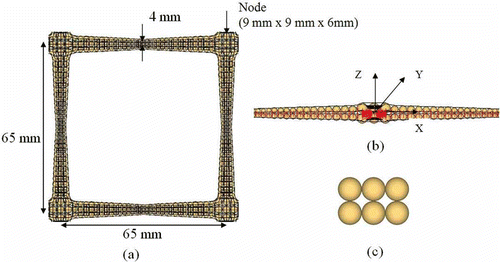
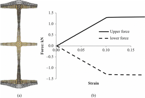
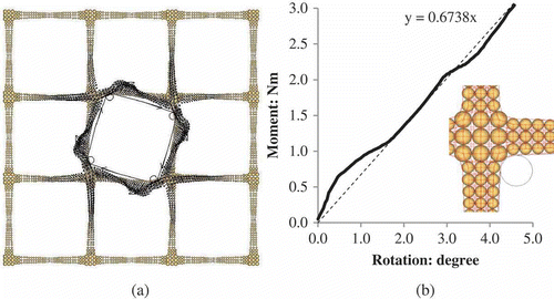
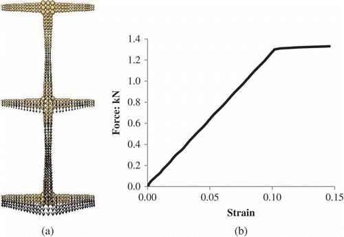
According to Konietzky et al. (Citation2004), the parameters for the geogrid were calibrated by three different tests: a single rib test, a single junction test and an in-plane rotation test. The force at failure for a single rib test is 1.37 kN at a failure strain of 10.5% and the force at failure for a single junction test is 1.26 kN at a failure strain of 9.2%. For an in-plane rotation test, the in plane rotation stiffness is 0.79 Nm/degree. The calibration was performed in terms of stiffness and strength. and show the tension test geometries and simulation results. The single junction test was modelled using three nodes. The upper node was fixed to simulate the junction clamp and a constant velocity was applied at the lower row of particles. The same model as used for the single junction test was used to model the single rib test. A constant velocity was applied at both the upper and lower rows of particles. The axial strain and the resulting forces at the upper and lower rows of particles were monitored during the test. The parallel bond is depicted as a cylinder of elastic material in PFC3D. So the geogrid model has such a linear elastic-perfectly behaviour. Experiments show some minor plastic deformation at larger strain but these are considered negligible for the purpose of these simulations. The numerical in-plane rotation test, as shown in , was then performed to match the experimental results as much as possible. The four circles (cylindrical walls) and the adjoint plane walls are used to define a rigid block with no sharp corners, used to rotate the grid. The movement of these walls (i.e. the block) defines the rotation and the rotational rigidity was chosen by the trend line as shown in which is a simple line of best fit. It is obvious that a better match would not change the general behaviour. shows the calibrated set of parameters in PFC3D. These micromechanical parameters can be subdivided into deformation parameters (parallel bond stiffnesses) and strength parameters (parallel bond strengths).
Table 2. Micromechanics parameters for the biaxial geogrid model
Figure 8. Single junction test: (a) test geometry test geometry and velocity vectors during the test; (b) force-strain plot.
3.3 Numerical modelling procedure for pull-out test
Figure 11 shows the numerical model for the large box pull-out test using a two-ball clump to represent each ballast particle. The dimensions of the pull-out box and the geogrid size and position are the same as that used in the laboratory experiments. The procedure of sample preparation followed the experimental sample preparation. At the beginning of preparing the sample, an initial sample of spheres was generated within the top of the box without overlapping and then expanded to their final size (40 mm). After that, the position of each sphere was found, and then the spheres were replaced by the two-ball clumps with the same volume, which were given random orientations. The clumps were directly deposited in the pull-out box and cycled to equilibrium under a changing gravitational acceleration which was reduced gradually from 98.1 m/s2 to 9.81 m/s2. The clumps located higher than the middle of the slot were then deleted. Afterwards, the remaining sample below the slot was compacted using cyclic loading by a horizontal wall. The geogrid specimen was then installed at the middle of slot, with the geogrid protruding outside of the slot. Two frictionless walls near the slot were generated to prevent the geogrid layer from going through the right-hand walls during pull out. Because of the ‘soft contact’ approach in PFC3D, balls and walls overlap to give contact forces and it is possible for balls to penetrate through walls according to the contact law. This would artificially increase the pull-out resistance. The upper half sample was again generated using the same expansion method, replaced by the two-ball clumps and then compacted and cycled to equilibrium. To make the lower half and upper half sample densities as consistent as possible, the upper clumps located higher than 200 mm based the position of geogrid were deleted. Then the system was compacted again as before. In the experimental pull-out test, a wooden bock slightly smaller than the internal dimensions of the box was placed to distribute the surcharge. Similarly, a simulated block that consists of 600 parallel bonded balls was used at the top surface to apply a vertical load, as shown in The spheres around the simulated block are smooth to prevent trapping between the simulated block and the pull-out box. The constant surcharge was provided by the self-weight of the loading spheres using an appropriate density for these spheres to give the required surcharge. For the sample of two-ball clumps, two different vertical loading situations were considered: 0 and 0.5 kN. shows the specimen of two-ball clumps with the embedded geogrid at this stage of the simulation. The specimen contained 1605 two-ball clumps and the geogrid of 6672 parallel bonded balls. For these simulations, the normal and shear stiffness of the particles were 1.0 × 10⁸ N/m and the stiffnesses of the walls were set the same values as the particles. The ball, box and geogrid friction coefficients were all set to be 0.6. The density of the ballast particles was 2600 kg/m3.
Figure 11. DEM of large box pull-out test: (a) embedded geogrid specimen and simulated surcharge; (b) two-ball clump; and (c) sample of two-ball clumps under 0.5 kN surcharge.
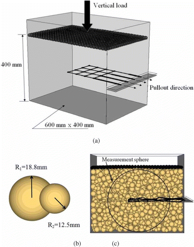
A horizontal pull-out rate of 5 mm/s was given to the spheres at right-hand end of the geogrid. To avoid any dynamic effect, the pull-out rate gradually increased linearly with time from zero to the final rate at the beginning. The simulation was terminated at a total pull-out displacement (i.e. the displacement of the right-hand end of the geogrid) of 60 mm. It should be noted that the total pull-out displacement was only 50 mm in the laboratory test. During the simulation, the pull-out force, the pull-out displacement, the axial deformation of longitudinal ribs and the porosity (using a measurement sphere in PFC3D as shown in ) were recorded. It is should be noted that no facility is available in PFC3D for calculating the porosity of a sample of clumps comprising more than two particles within each clump.
3.4 Results and discussion
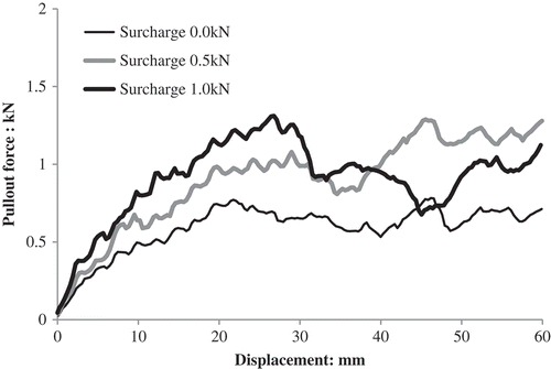
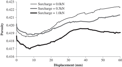
shows the development of the total pull-out force for the sample of two-ball clumps under different loading conditions. It clearly shows that up to a displacement of approximately 20 mm, the peak force was larger for a greater surcharge. However, the confinement caused by 1.0 kN surcharge does not seem to have enhanced the interlocking effect beyond the peak pull-out force. This is likely to be attributed to a severe unrecoverable deformation of the geogrid after the peak force under 1.0 kN surcharge. shows evolution of the particle porosity within the measurement sphere for the sample of two-ball clumps. It indicates that the sample contracted until a displacement about 8 mm and then dilated. Moreover, the displacement at the peak pull-out force is associated with the maximum rate of dilation of the sample given by the measurement sphere.
Figure 13. Particle porosity as a function of pull-out displacement for different values of surcharge.
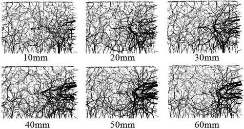
shows the development of contact force distributions for several stages during the pull-out test. It should be noted that contact forces are all drawn at the same scale. These figures display the strong contact forces in the vicinity of the geogrid area, which clearly shows the interlocking effect. This is in agreement with the simulation modelled by McDowell et al. (2006). It can be seen that, the clump ballast particles arch around each transverse rib during pull-out. Furthermore, the arching is concentrated on the back two transverse ribs after approximately 50 mm displacement. The principle interlocking area has a range of about 10 cm thickness either sides of the geogrid.
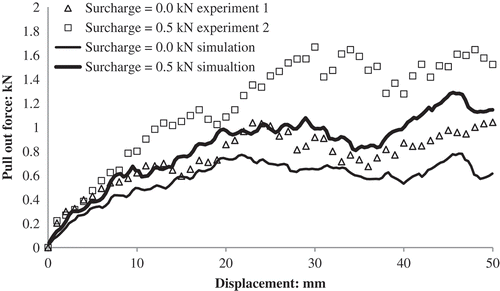
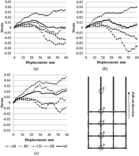
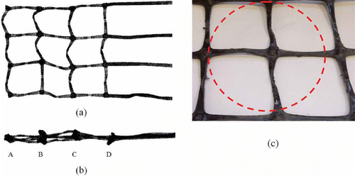
Compared to the experimental results, it can be seen from that the pull-out force was well predicted by the DEM simulations especially up to approximately 20 mm displacement. However, it appears that the DEM simulations underestimate the pull-out force after a displacement of approximately 20 mm. It is believed that, owing to less angularity of the two-ball clumps, interlocking between the particle and geogrid is reduced compared to the real experiments comprising more angular particles. Besides, a broadly-graded sample gives higher shear strength than a single-sized sample. Therefore, future work will model a graded sample of more angular clumps. shows the evolution of axial strain between several observation points of the longitude rib AE. The positive value means that the geogrid nodes are further apart; the negative value means that the grid nodes are closer together. With an increase in the surcharge, the axial strain of each ribs apart from rib BC increased and more nodes move further apart. shows the deformation of geogrid sample under 0.5 kN surcharge in simulation and the experiment. The geogrid model shows some realistic deformation behaviour of the geogrid. It clearly displays the extensive deformation of the grid, and also deflection can be seen from the side view. This deflection explains why, for the longitude ribs AB and BC, negative strains are observed in , as the nodes are closer together than before pullout.
4. Conclusions
Laboratory large box pull-out tests have been performed on biaxial and triaxial geogrids embedded within a ballast sample. The pull-out force has been measured as a function of displacement for the different grids and under different surcharges. A new DEM model for the geogrid has been developed by bonding two layers of small balls together to form the required geometry using parallel bonds, and calibrated by simulating standard tests. Two-ball clumps were used to represent the real ballast particles. The DEM simulation has given valuable insight into the interaction between ballast and geogrid under different surcharges, although the mobilised pull-out force was slightly less than experimental result after a displacement of about 20 mm. This is thought to be a function of both the uniform particle size and the roundness of the two-ball clumps, compared to the well-graded, angular ballast particles in the laboratory tests. Future work is required to model a graded sample of more angular clumps. The main conclusions from the experimental work and simulations presented in this paper are:
Experimental results indicate that geogrid aperture size plays a more influential role than tensile strength or thickness of ribs.
The triangular aperture, coupled with vertical rectangular rib cross-section and junction efficiency, gives greatly improved ballast confinement and interaction compared to biaxial grids.
The DEM simulations have been shown to provide good predictions of the trend of pull-out force especially for the initial 20 mm displacements. Both the pull-out forces of the experiments and the simulations increase rapidly and reached the peak force at displacement of approximately 23 mm and 30 mm under 0 kN and 0.5 kN surcharges respectively.
The two-layer geogrid using parallel bonds and balls of varying sizes to model the required geometry, calibrated against standard tests, facilitated much improved modelling of the geogrid, when compared to the experimental results. This method of modelling the grid will be of great use in modelling triaxial and other geogrids using DEM in the future.
Acknowledgements
The Authors wish to thank Dr J.F. Ferellec for valuable advice for the geogrid modelling.
References
- Brown, S.F., Kwan, J. and Thom, N.H., 2007. Identifying the key parameters that influence geogrid reinforcement of railway ballast. Geotextiles and Geomembranes, 25 (6), 326–335.
- Cundall, P.A. and Strack, O.D.L., 1979. A discrete numerical model for granular assemblies.Géotechnique, 29 (1), 47–65.
- Tensar, 2009. Tensar Geosynthetics in Civil Engineering. Blackburn: Tensar International Ltd.
- Tensar, 2010. TrIAx brochure. Blackburn: Tensar International Ltd.
- Itasca, 2003. Particle flow code in three dimensions. Minnesota: Itasca Consulting Group, Inc.,
- Koerner, R.A., Milligan, G.W.E., Sarsby, R.W. and Dubois, D., 1989. Analytic behaviour of geogrid anchorage. Proceedings of the Geosynthetics’ 89 Conference, IFAI, San Diego, California, USA, 525–536.
- Konietzky, H., te Kamp, L., Groeger, T. and Janner, C., 2004. Use of DEM to model the interlocking effect of geogrids under static and cyclic loading. Numerical Modelling in Micromechanics via Particle Methods. In: Y. Shimizu, et al., eds. Proceedings of the 2nd International PFC Symposium. October 2004, Kyoto, Japan. Leiden: Balkema, 3–11.
- Konietzky, H., te Kamp, L. and Hainbuchner, E., 2000. Tensar geogrid modelling. Progress report, prepared for Tensar International. Gelsenkirchen, Germany: ITASCA Consultants GmbH.
- Kwan, J., 2006. Geogrid reinforcement of railway ballast. Thesis (PhD). The University of Nottingham.
- Lim, W.L., 2004. Mechanics of railway ballast behaviour. Thesis (PhD). The University of Nottingham.
- McDowell, G.R. and Lim, W.L., 2005. Discrete element modelling of railway ballast. Granular Matter, 7 (1), 19–29.
- McDowell, G.R., Harireche, O., Konietzky, H., Brown, S.F.and Thom, N.H., 2006. Discrete element modelling of geogrid-reinforced aggregates. Proceedings of the Institution of Civil Engineers-Geotechnical Engineering, 159 (1), 35–48.
- McDowell, G.R. and Lu, M., 2007. The importance of modelling ballast particle shape in the discrete element method. Granular Matter, 9 (1–2), 69–80.
- Palmeira, E.M. and Milligan, G.W.E., 1989. Scale and other factors affecting the results of pull-out tests of grids buried in sand. Géotechnique, 39 (3), 511–524.
- Zhang, J., Yasufuku, N. and Ochiai, H., 2007, A few considerations of pull-out test characteristics of geogrid reinforced sand using DEM analysis, Geosynthetics Engineering Journal, 22, 103–110.
- Zhang, J., Yasufuku, N. and Ochiai, H., 2008. Discrete element modelling of geogrid pull-out test. In: G.X. Li, et al., eds. Geosynthetics in Civil and Environmental Engineering. Shanghai, China, Springer, 11–14.
