
ABSTRACT
Unexpected and unforeseen geotechnical events cause large cost increases in geotechnical engineering projects and threaten construction workers’ health and safety all around the world. Practical tools and guidelines for how to implement structured and effective risk management methods in geotechnical engineering projects are however few and rarely applied. The Swedish Geotechnical Society has therefore published a methodology for this issue. A key activity in this methodology is to create an understanding of and to interpret the geotechnical context in which the project is to be carried out. This paper presents a guide for how practising geotechnical engineers, hydrogeologists, and other related professionals can perform this activity in a structured way. The procedure is illustrated through the foundation design for a new office building in a geotechnically challenging environment.
1. Introduction
Unexpected and unforeseen geotechnical events and uncertainties commonly impede the progress of geotechnical engineering projects all over the world, as they cause cost increases and time delays. The annual failure cost is an enormous problem for the construction industry, as is evident from the reported figures: for example, both Sweden and the Netherlands are subjected to annual failure costs amounting to hundreds of millions of euros or even billions of euros (SGI Citation2013; van Staveren Citation2013). Although comprehensive compilations of failure costs in geotechnical engineering projects are rare, challenges related to implementing geotechnical risk management have been reported by for example van Staveren (Citation2006), Smith (Citation2008), and Tonks, Gallagher, and Nettleton (Citation2017). Geotechnical failures due to inadequate designs and risk ignorance during execution are naturally not only an issue for the project cost, but possibly more importantly also constitute threats to workers’ safety as well as to the surrounding environment.
The Swedish Geotechnical Society, which is the Swedish branch of the International Society for Soil Mechanics and Geotechnical Engineering, has over the last decade strived to provide practising Swedish geotechnical engineers and hydrogeologists with modern and practical tools and methods to improve the quality of their risk management work. As a result of the general lack of Swedish and international literature on geotechnical risk management, a general methodology for structured risk management in geotechnical engineering projects was first issued in 2014 and recently updated and translated into English (SGF Citation2017). Spross, Olsson, and Stille (Citation2018) provided a discussion of its main features and Spross et al. (Citation2015) gave a brief application example by discussing how the methodology could have been applied to the design of the failed construction of the foundations of an equestrian sport centre in Sweden. Similar efforts to improve the risk management work in geotechnical engineering projects have also been reported from the Netherlands; see for example van Staveren (Citation2006, Citation2009, Citation2013).
There is, however, still a need for practical guidelines on how to organise and perform the geotechnical risk management work so that it is executed with high quality. In particular, we recognise that many practising geotechnical engineers find it challenging to create the necessary understanding of the geotechnical context in which the geotechnical engineering project is to be carried out. As we see it, this understanding is fundamental to facilitate the engineer in identifying any potential threats to the success of the project.
In this article, we discuss how practising engineers can create an understanding of and interpret the geotechnical context in a structured way. This initial work by the engineer creates the knowledge base for the subsequent risk identification, risk analysis, and risk evaluation steps (using ISO-31000 terminology). The guide presented in this paper concerns this initial work, which by nature is qualitative (as quantitative, more detailed analyses belong to the subsequent risk analysis step), but nonetheless critical, because if the geotechnical context is not properly understood, important risks may not be recognised. The guide is the result of a recently completed development project directed toward practising geotechnical engineers and hydrogeologists in Sweden (Olsson et al. Citation2019). As the topic of risk management is little discussed in the international literature, we hope that this article will inspire the geotechnical community to improve the quality of their risk management work all around the world.
2. Principles of structured geotechnical risk management
2.1. Basic concepts and presumptions
As we discuss in detail in a previous paper (Spross, Olsson, and Stille Citation2018), the overall objective in performing risk management in a geotechnical engineering project is to ensure that sufficient quality is achieved in the performed work. By quality, we mean “the ability of a project to satisfy or exceed the client's explicitly or implicitly stated, justifiable requirements and wishes” (cf. ISO 8402 Citation1994). Following the ISO 31000 (Citation2009) standard for risk management, we define risk as the “effect of uncertainties on objectives”, where the main objective in this context is indeed the achievement of sufficient quality of the works within budget and time plan constraints. We have found it natural to only consider negative effects, because this follows most engineers’ perception of the risk concept and, regardless, the upside (to end up with higher quality than aimed for) is rarely rewarded in today's contractual formats. For convenience, we use the term geotechnical risk for all risks in a geotechnical engineering project, as there is in our opinion no difference in risk management principles for risks originating from geotechnics and risks originating from other sources. A fundamental presumption is that the risk management work in a geotechnical engineering project needs to be carried out by the practising engineers as a part of their everyday work. Risk management must not be an isolated activity, but needs to be fully integrated in all project activities. This presumption is based on the idea that the engineer that carries out a task is also best placed to assess its accompanying risks.
2.2. The ISO 31000 risk management process
The structured risk management methodology suggested by the Swedish Geotechnical Society (SGF Citation2017) is compatible with the iterative work procedure suggested by ISO 31000 (2009) (). Here we provide an overview, but refer to Spross, Olsson, and Stille (Citation2018) for a more extensive discussion of its principles. Its implementation in rock engineering design has recently been discussed by Spross et al. (Citation2020a).
Figure 1. The iterative risk management process. This paper concerns step 2 mainly.
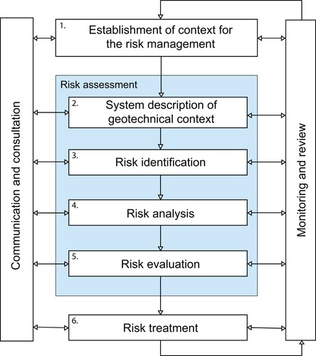
The first step is to organise the engineering tasks from a risk management perspective within one's own project organisation. This includes:
to decide the extent and limitations of the planned risk management work with respect to the geotechnical context,
to clarify who is responsible at the present project phase for achieving satisfactory quality within the budget and time plan constraints. This person – the risk owner – makes all decisions regarding risks that may threaten this objective,
to assign necessary resources to the risk management work,
to establish communication procedures so that the result of the risk management work reaches the right people,
to establish guidelines for risk acceptability in the project (for some risks, e.g. those related to structural safety and work environment, the risk acceptability is often regulated by legislation, but project guidelines may of course also be stricter).
The second step is to establish a clear picture of the project objectives and the related quality requirements. To achieve this, the engineering problem needs to be broken down into definable functions that are to be fulfilled by the project works. These functions are interlinked, and to establish a complete picture these relations must be understood. Moreover, the possibility to fulfil the functions is affected by external factors, which include, but are not limited to, geotechnics. To provide a base for the subsequent risk management (steps 3–5 below), we suggest that a system description is needed. This second step constitutes the main focus of this paper. A methodology is described in the next session and its potential implementation is discussed in a practical example.
The third step is to identify the hazards (sources of potential, negative consequences) that threaten the project objectives as well as their respective consequences. This is a critical task in the risk management work and requires a thorough understanding of the geotechnical context.
The fourth step is to analyse the identified risks, which means describing them in terms of likelihood and severity of their consequences.
The fifth step is the evaluation of whether the analysed risks are acceptable or not in relation to the project's risk acceptability guidelines. This decision is made by the engineer in charge (i.e. the risk owner). Steps 2–5 are often denoted risk assessment ().
Risks that are found not acceptable are sent for treatment in the sixth step. This implies executing risk-reducing measures, such as reducing the likelihood of occurrence or the project's exposure to the consequences. As risk treatments may introduce new risks, an iterative work process is required, as the new risks also need to be identified, analysed, evaluated, and potentially treated.
The risk management work needs to be communicated throughout the project to all parties involved in the project. This is required in order to establish a risk-aware culture that facilitates risk-informed decisions in all project phases. Challenges in communicating geotechnical risks are further discussed by Sartain, Mian, and Free (Citation2015). To facilitate high quality in the risk management work, it should be reviewed continually as a part of the project's quality assurance, the implementation of which is discussed in detail by Stille, Sturk, and Olsson (Citation1998) and Stille (Citation2017). In particular, the execution of decided risk treatments needs complete integration in the quality assurance planned for the construction works, to ensure that risks are reduced as planned. For geotechnical engineering projects, a dualistic quality system is required: not only shall things be done right, but the large uncertainties emphasise a need to ensure also that the right things are done. Key tools include milestones and tollgates in the project execution, which allow project management to control critical risks directly. Milestones require that some specific action must be taken when some predefined events occur. Tollgates must not be passed until the project manager gives explicit permission.
3. Methods to create an understanding of the geotechnical context
3.1. System descriptions of functions and external factors
As previously established, geotechnical risk is the effect of uncertainties in a geotechnical engineering project on the project objectives. A key activity in geotechnical risk management is consequently to understand and interpret how the prevailing uncertainties may affect the possibility of achieving the project objective (where the objective, for example, can be to deliver a geotechnical engineering structure of sufficient quality to a client). To describe this geotechnical context of the project, system descriptions can be used to show how project requirements and affecting uncertainties are interlinked. This understanding of the geotechnical context is the basis of the subsequent risk identification. If the geotechnical context is not understood comprehensively, risks are easily missed or neglected and decided treatments for other risks may be less suitable. A consequence may be substandard quality in the final product. Comprehensive understanding shall here be interpreted as what can be inferred from the available information when reviewed critically and holistically with respect to possible hazards.
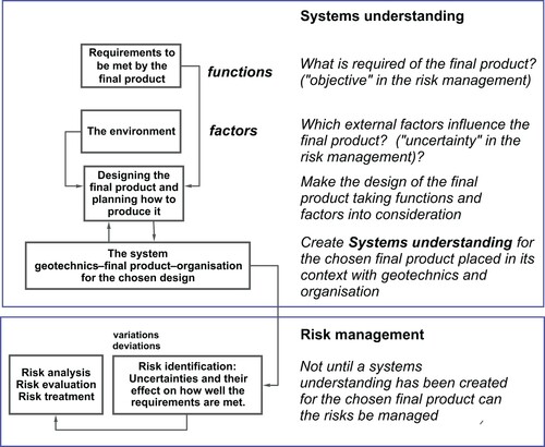
From a system view, we suggest describing the geotechnical context by using necessary or desirable functions of the project's final product as components of the system (). Achievement of the complete set of functions is by definition equivalent to the project objective. The possibility to achieve these functions can be linked to underlying external factors, which contribute with uncertainties that may affect the achievement of the functions (cf. the definition of risk as the “effect of uncertainties on objectives”). Such organisation of the bigger picture aims to highlight the requirements that are to be met in project: that is, what are the critical functions that need to be satisfied? Note that to facilitate identification of relevant risks, one must establish a rather detailed idea of the final product, for example in terms of general design and execution of a planned geotechnical engineering structure. (Revisions are however expected, considering the iterative nature of the risk management work.)
Figure 2. Functions and factors as key inputs to the systems understanding, which serves as a basis for the subsequent risk identification.
In the following subsections, we describe general principles of how a geotechnical engineer or related professional can work to create a comprehensive understanding of a geotechnical context in a geotechnical engineering project. Detailed examples of functions, their combinations into a system, and related external factors are provided in tables in the section Practical example.
3.2. Methods to describe technical systems
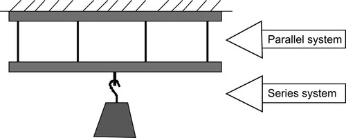
A technical system can be defined as “a group of interacting or interrelated entities that form a unified whole”. The entities need not be physical, but can also be for example organisational, procedural, or financial. The relationship between two entities can be described as either a series system or a parallel system. These basic systems can be combined into more complex systems when there are more than two entities (). In describing a geotechnical engineering project as a technical system, such entities can be used to describe the necessary or desirable functions.
Figure 3. The two basic types of relationship between entities in a system.
To visualise the technical system, reliability block diagrams and fault trees are commonly used (Aven Citation2008), to supplement preliminary drawings of the planned structure. Such visual tools can give valuable information about how critical a particular function is to the project. In this paper, we use reliability block diagrams in the practical example.
3.3. Categories of functions that are needed to achieve project objectives
We find that the functions of a geotechnical engineering project that are needed to achieve the project objectives can be divided into four categories:
Fulfilment of quality requirements of the final product,
Fulfilment of requirements regarding budget restraints and time plans,
Fulfilment of requirements regarding acceptable environmental impact and third-party disturbance both during execution and such caused by the final product,
Fulfilment of requirements regarding acceptable work environment, including structural safety during execution.
Functions related to quality requirements include requirements of for example structural safety, durability and serviceability of the final product. Many requirements in this category originate from structural design codes, laws and regulations, while others originate from the client's wishes. Typically, the project-specific functions are found by analysing the purpose of the project and any limitations to its execution imposed by economic considerations, time plans, and laws and regulations; if some matter is important to the project, it can be described as a function.
3.4. Important technical, organisational, and contractual aspects
A system with a given set of functions can be organised differently, which makes the system (i.e. the final product) more or less sensitive to strain and disturbance. Normally, it is desirable that the system is resilient, meaning that it has a high ability to absorb or avoid damage without suffering complete failure. For a geotechnical engineering project, this can be exemplified with having several transport routes for construction material, in case one of them happens to be closed.
Systems should normally also be robust, which means that a minor negative event should not cause disproportionally large damage in relation to the cause of the event: An incorrectly assembled, small structural part should not result in complete collapse of the structure.
A number of functional requirements in a geotechnical engineering project are related to the organisation itself. The project needs to be organised so that decision paths are clear and the organisation has established routines for internal and external review and control to minimise human error.
Two key functions in all geotechnical engineering projects are satisfying the budget restraints and following the determined time plan. These functions are closely linked to the formulations of any negotiated contracts between the involved parties. Common contractual disputes in geotechnical engineering projects are caused by vague clauses regarding risk sharing, which means that the contract is unclear regarding the ownership of the risk (i.e. who pays for the additional cost if the risk occurs). This circumstance creates a special set of risks: not only is it uncertain whether a negative event will occur, but there is also uncertainty in whether one's own organisation is responsible for the consequences. An important aspect in creating an understanding of the geotechnical context is therefore to clarify, as much as possible, what risks are owned by one's own organisation and what risks belong to other parties. Some risks may however be in a grey area, for which the contract does not specify the risk owner. In such cases, each party needs to manage the risk that a certain identified risk is owned by one's own organisation.
A practical tool to manage such grey-area risks is the use of Geotechnical Baseline Reports (GBR). They establish baselines regarding risk allocation of uncertain site conditions. Risks that are associated with site conditions consistent with or less adverse than these baselines are allocated to the contractor, while more adverse situations are allocated to the client. It is essential to understand the difference between the purposes of the GBR and the geotechnical design documents: the former in principle only define the risk allocation for the potential scenarios regardless of how likely they are, while the latter often contain information about the characteristic ground conditions for the design. The baselines of a GBR are however not necessarily consistent with the characteristic ground conditions: a baseline for soft soil layer thickness being “2 m, +/–0.5 m” shall not be interpreted in the sense that the client expects the layer thickness to be between 1.5 and 2.5 m, but in the sense that the contractor has the right to be compensated if the thickness turns out to be outside of this range. Further details on the application of GBRs can be found in Essex (Citation1996), Hatem (Citation1998), and van Staveren and Knoeff (Citation2004). Other contractual aspects on geotechnical risks are discussed by e.g. Gransberg and Tapia Pereira (Citation2016) and Gransberg et al. (Citation2018).
3.5. Underlying external factors
The possibility to fulfil the functions depends on many things; we call them external factors, which by definition are those aspects in the project that contribute with uncertainties that may affect the achievement of the functions. In geotechnical engineering projects we find that these uncertain underlying factors generally can be categorised into a number of categories, which are grouped in . Thus, external factors can originate from anything in the physical or organisational context of the project.
Table 1. Lists of categories of potential underlying external factors that may cause uncertainty in the fulfilment of the functions in geotechnical engineering projects.
3.6. What does it mean to interpret the geotechnical context?
To achieve a comprehensive knowledge base for the subsequent risk identification, one needs to identify and analyse the underlying factors that may contribute with uncertainty to the project. We call this process interpreting the geotechnical context. This process implies creating a conceptual model of the expected geotechnical behaviour in the area for the duration of the engineering works. The conceptual model needs to be created with an understanding of what the model will be used for later: What decisions will be based on the model? For whom is the model created – client or contractor? For example, if high-stake decisions are to be based on the model it may require more extensive preparation. Clients and contractors may also be more or less interested in different types of information.
The interpretation of geotechnical context includes assessing the prevailing uncertainties with respect to the degree of knowledge of both the geology and the geotechnical conditions at the site (epistemic uncertainty), as well as the actual inherent spatial variation of the geotechnical properties that are known to be present. The degree of knowledge of the site needs to be improved until the ground conditions are known with satisfactory certainty with respect to the design issues of the planned works and the planned design verification method (e.g. analytical or numerical calculations, prescriptive measures, or the observational method). Better knowledge is normally achieved with additional site investigations. The interpretation of the geotechnical context also normally includes assessments of any relevant geotechnical parameters that will be used in design calculations or when selecting the method of execution (among other things).
Ramasesh and Browning (Citation2014) discuss strategies for how to deal with different types of uncertainties in projects. The most common geotechnical uncertainties belong to the group known unknowns; these are uncertainties that can be estimated in a probabilistic sense based on site investigations and other sources, like the variation in thickness of a soft soil layer or effects of known measurement and transformation errors.
A crucial – but difficult – aspect of the interpretation of the geotechnical context is however to uncover what the performed site investigations do not show. These are the famous unknown unknowns. Ramasesh and Browning suggest to divide these uncertainties into two categories, to make risk management more sensible. The unknowable unknown unknowns are unexpected surprises that the project by definition cannot be anticipated or prepared for. Risks caused by unknowable unknown unknowns must be accepted, but one can prepare the project organisation to respond to such emerging threats as they appear and thereafter adjust to the new situation, which should reduce the consequences; see Steen and Aven (Citation2011) on resilient systems and organisations.
There is also a group of uncertainties that Ramasesh and Browning (Citation2014) call knowable unknown unknowns. Many investigations of failed projects suggest that what at the time came as complete surprises likely could have been anticipated given due diligence. If extremely rare, highly consequential and almost unpredictable, the term “black swan” can be used (Taleb Citation2007; Paté-Cornell Citation2012). For the less extreme cases that in hindsight were reasonably foreseeable, Phoon (Citation2017) uses the term “grey swan”. These are important to try to uncover. Explanations for such knowable unknown unknowns in geotechnical engineering projects can be, for example, that selected investigation methods or investigation points were unsuitable or too few to detect some relevant design issue. Equipment may also be uncalibrated or badly operated, thereby producing inaccurate results. Caused by psychological effects, there is also the “grey rhino”, which is a highly probable, high-impact, but still neglected event, even though there was ample warning (Wucker Citation2016).
Ramasesh and Browning’s (Citation2014) suggested approaches to deal with knowable unknown unknowns are in many aspects in line with the general methodology that we propose in this paper. This includes for example addressing project complexity through decomposition of the project into sub-problems relating to key areas, which are equivalent to our definition of functions, and then gradually extracting the known unknowns in each key area. This structured process should point to areas of knowledge gaps that may hide potential unknown unknowns to investigate further. Checklists and predefined categories derived from previous experience may be of assistance, if used correctly as prompts for thinking. Ramasesh and Browning also recommend some behavioural approaches, including frequent communication, a balance of central control and local autonomy in decision making, and cultivating a risk awareness in the project. The latter includes development of systems thinking that acknowledges the complexity of the project and a need for multiple perspectives in decision making. Phoon (Citation2017) suggests that some unknown unknowns can be counteracted by increasing the robustness in the structural design. Stille (Citation2017) emphasises the need to organise the project so that qualified staff, e.g. engineering geologists, is present on site, so that geological warning bells from both knowable and unknowable unknown unknowns can be heard and interpreted as early as possible, i.e. building a resilient organisation that catches also any potential grey rhinos. These recommendations are, in fact, all in line with SGF’s (Citation2017) risk management methodology for geotechnical engineering projects, in which the present paper has its basis.
When the geotechnical context has been interpreted and put together in a conceptual model, the engineer makes a first assessment of possible and reasonable engineering solutions with respect to the situation at hand. Comparing these solutions, those best suited are put forward for a more detailed assessment of the associated risks in the detailed design work. As a basis for this risk assessment, each selected engineering solution is further studied to gain a more comprehensive interpretation of the geotechnical context for the considered site. This initial work (step 2 in ), which is the focus of the present paper, gives the involved geotechnical engineers a good starting point in the continued project planning, which includes identifying risks in terms of threats against the project and their potential consequences (step 3), analysing the likelihood and severity of the identified risks (step 4), evaluating whether the risks can be accepted or not (step 5), and treating any unacceptable risk by reducing or allocating it (step 6).
4. Practical example: tendering in the foundation of an equestrian sports centre
This practical example is based on a real case from the 1990s, where a sheet-pile wall failed during the excavation for the foundation of a new office wing. The details of the failure and how structured risk management procedures in design and execution could have reduced the probability of failure have been discussed previously by Spross et al. (Citation2015).
In the present paper, we instead look into the tendering phase of this old construction project to exemplify how the bidding contracting firm could today have applied modern risk management tools to better understand and interpret the geotechnical context specifically, i.e. step 2 in .
4.1. Overview of construction project
The owner of an equestrian sports centre near Stockholm plans to expand by making an extension to an existing building. The owner therefore calls for tenders for a design and build type of contract for the geotechnical works. The contract will include a new five-storied office wing with a basement. The construction site is delicately located right next to both the racetrack and an existing building, which harbours sensitive computer equipment in the basement. The excavation for the new building's basement will be close to the existing structures.
The tender documents include:
Functional requirements and a description of the building,
Reported results of geotechnical investigations carried out by a consultancy firm on behalf of the client
A statement of risks identified by the client, limited to the following issues:
the ongoing racetrack activities must not be disturbed, which means that the racetrack itself should remain flat and even (as horses may be injured if unexpected soil movements create cracks in the ground)
the pile foundation of the existing building must not be damaged
the status of the existing building shall be controlled with respect to settlement and vibrations (base values are however not provided)
(Note that these identified “risks” rather can be considered functions, cf. ).
Requirements for a risk assessment performed by the contractor regarding the proposed excavation and foundation methods, which shall be approved by the client
A requirement for a risk assessment for the complete contract, to be submitted in the bidding documents
The tender documents state that both driven and bored piles are acceptable and that the basement shall be watertight and withstand an uplift pressure corresponding to the maximum expected level of the adjacent stream Bällstaån.
4.2. Establishment of risk management procedure for the tendering
The tendering phase concerns the contracting firm's preparation of a competitive bid to be submitted to the client. Risk management is essential during this phase, as the contractor needs to identify and assess the main risks in the project to come up with a technically suitable design and execution that also constitutes a competitive bid. This requires the contractor to create a good understanding of how the geotechnical conditions, as well as other external factors, affect the chances of successfully executing the project. (Such analyses are of course performed in all projects in one way or another, but we believe their quality can be significantly improved with the proposed risk management methods.)
As a first step in preparing the bid, the contractor tailors a risk management procedure in the organisation for this specific project: the person responsible for the bid ensures that the following aspects are considered by the involved people (cf. the corresponding list in the section The ISO 31000 Risk Management Process).
Extent of the risk management: The task is limited to geotechnical risks associated with the excavation, the foundation, and the logistics associated with the excavated material. At this point it is judged that the project is technically challenging, but not to such a degree that external expertise is required (this follows from the assigned risk management class, as proposed in SGF (Citation2017), but not further discussed in this paper).
Risk owner: During the tendering phase, the department head for civil engineering works is recognised as risk owner (decision maker).
Resources: The risk owner ensures that the risk management can be performed as a part of the regular bidding preparation work.
Means of communication: The results of the geotechnical risk management shall be documented and submitted to the involved geotechnical engineers and quantity surveyors.
Risk acceptance: Risk acceptance criteria related to Swedish design codes, Environmental Court rulings, and workers’ safety regulations shall be complied with. Regarding financial risks (or other similar damage not defined by the other criteria), concrete risk criteria are difficult to establish on a general level. Therefore, a transparent basis for the risk acceptance decision, in terms of structured and clear descriptions of the associated risks, is essential for the decision maker (risk owner).
4.3. Understanding the geotechnical context
4.3.1. Identifying required and desirable project objectives
Construction projects involve many disciplines, which must all work together for the project to be successful. This means that the geotechnical works are carried out in a larger context that includes for example acquisition of building permits, coordination with other subcontract works such as the erection of the building and surrounding ground works, and that the contractual details are acceptable with respect to for example time plans and compensation. Focusing on the geotechnical works, these can be divided into three main functions: Foundation, Excavation, and Handling of excavated soil. As shown in , these main functions can all be divided into a number of sub-functions. provides details on some of them for illustrative purposes.
Figure 4. Reliability block diagram visualising necessary and desirable functions of the project. All are in series except the potential options of technical solutions.
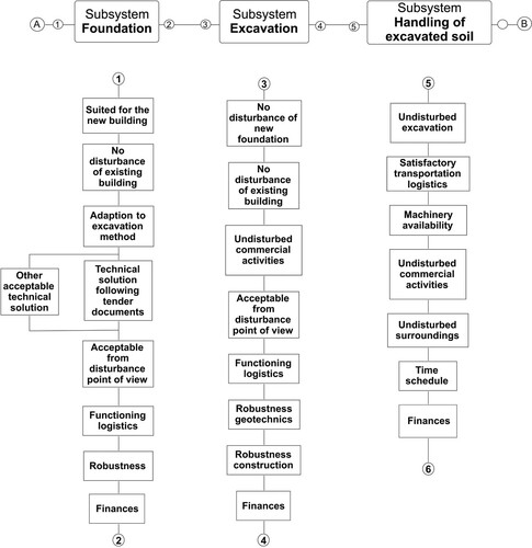
Table 2. Descriptions of some of the functions in .
4.3.2. Understanding the underlying factors
To create an understanding of how any underlying factors may affect the identified project objectives, a clear description of their connections is required. This becomes a technical system consisting of the surroundings, the geotechnics and the planned construction works. Its creation is an iterative process, because the surroundings affect the viability of the technical solution and different technical solutions may require knowledge of different aspects of the surroundings. The purpose of this process is to identify and consider all aspects that may affect how the construction work is carried out. Some relevant external factors that have been identified for the discussed case are described in .
Table 3. Descriptions of identified external factors that may affect the project objectives.
4.3.3. Interpreting the geotechnical context
As interpretation of the geotechnical context for this structure is an extensive task, consisting of a variety of underlying external factors (), we limit the discussion to the geotechnical properties, as these were most vital to the project. Based on the available knowledge, a conceptual model is created that describes what can be expected in the area. During this work, it is concluded that the undrained shear strength may vary considerably in the area (), as the two investigated locations differ significantly in observed values even though they are quite close to each other. This conclusion is also supported by the data from the weight soundings, which also indicate variation in shear strength. It can therefore not be ruled out that the undrained shear strength at some locations is even less than the lowest measured value 9.6 kPa.
Figure 5. Undrained shear strength measured at two locations at the construction site (see for locations).
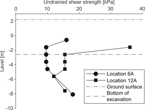
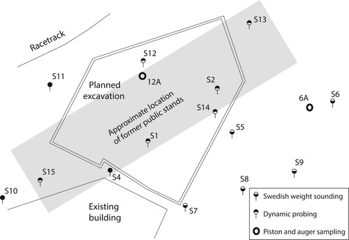
Studying the information in more closely, the reason for the observed variation in undrained shear strength could likely be caused by the former public stand, which previously occupied the area (listed under Existing structures). The fill on which the wooden stand was erected is likely to have caused consolidation of the underlying clay locally at the specific spot where some of the soil samples were taken (location 12A in ). The understanding of that there is an underlying specific cause for the higher measured values in one of the locations where soil samples were taken is critical to this geotechnical design case; without this understanding a too high design value for the undrained shear strength can be selected erroneously.
Figure 6. Plan view of the planned excavation and the locations of the geotechnical investigations, overlaid with an old map showing the location of the public stand.
4.4. Potential design solutions
4.4.1. Summary of gained understanding of the geotechnical context
Before the potential design solution is preliminarily selected, the available knowledge and understanding needs to be summarised and evaluated. The excavation is approximately 26 by 36 m2. The bottom of the excavation will be in clay, approximately 4.8 m below the ground level. The undrained shear strength of the clay is extremely low, at about 10 kPa generally, but with potential variations. Settlements are to be expected, because of the highly compressible clay. The requirement to not disturb the nearby racetrack is a complicating factor. The following subsections discuss some potential design solutions given this established geotechnical context.
4.4.2. Excavation with sloping sides
A rough calculation shows that an excavation with sloping sides will have a too low safety margin, even if a part of the crest is unloaded. The option is discarded.
4.4.3. Soil improvement with dry deep mixing columns and steeper sides
Calculations show that it is quite possible to achieve acceptable slope stability with this design option. However, installing the columns may be time-consuming because of the fill layer. Moreover, the mixing may cause a temporary decrease in shear strength before the columns have cured. Some disturbance of the surroundings caused by the machinery can also be expected.
4.4.4. Excavation within anchored or braced sheet-pile walls
Calculations of total stability, heave, and boiling conditions show that anchored sheet-pile walls may be possible, but that this solution will likely require several waling levels. This option may require anchors to be installed beneath the existing building, which has a piling foundation that must not be damaged.
Braced sheet-pile walls are also deemed as viable, if they are combined with some specific stability-enhancing measures such as stepwise excavation in trenches and filling with gravitation concrete, which will provide ample counterpressure against heave and support the braces.
Regardless of type, the sheet-pile walls must not cause large settlements that may disturb the existing building and the racetrack. The structure must also be sufficiently robust, meaning that minor damage to the sheet-pile walls must not cause consequential damage that is out of proportion.
4.4.5. Sheet-pile walls combined with soil improvement
Installing sheet-pile walls in improved soil reduces the stability problems, but has a considerable disadvantage in that the combined approach will take a much longer time.
4.4.6. Interaction between excavation and foundation
Before a preliminary design solution can be selected, the interaction between the excavation method and the foundation works needs to be assessed. The following alternative foundation options are considered:
End-bearing driven piles installed from the ground surface after removal of the fill
End-bearing driven piles installed from the bottom of the excavation
Bored piles
4.4.7. Selected preliminary design solution
Based on the available options, excavation within braced sheet-pile walls is judged to be the most favourable excavation method (with respect to cost and technical challenge) if additional safety measures are implemented during the excavation procedure. This excavation method can be combined with end-bearing driven piles installed from a levelled ground surface. This is proposed as the main alternative for the tender in the upcoming risk assessment, in which the geotechnical engineer will identify threats and consequences for these geotechnical engineering works (cf. Risk identification step in ). Technical details of the main alternative are presented in the following paragraphs. At this point, rough assessments of the risks and costs of the other options are also made, but they are not further discussed here.
As preparation for the risk identification, a first draft of the excavation procedure is outlined. Considering the identified challenges, a highly competent geotechnical engineer is consulted to assist in the design work. The proposed procedure is judged to be feasible, even though safety margins are found to be rather small. The associated risks must however be assessed in the upcoming risk assessment before a final decision to accept the design can be made. Note that the risk owner is responsible for these decisions. The excavation procedure can be summarised as follows (the steps are illustrated in ):
Excavation to level +1.5 m both within the planned pit and on an 8 m wide unloading zone outside the pit.
Driving of sheet-pile walls.
Driving of piles for the foundation.
Excavation in trenches to level +/– 0 m.
Installation of wale beams.
Installation of temporary struts across the cut.
Excavation in the whole cut to level +/– 0 m.
Careful excavation by segments to level –2.6 m (each segment is 13 m × 5 m) without damaging the piles.
Casting of the corresponding concrete slab after each excavated segment.
Installation of struts against the concrete slab on two levels after each excavated segment.
Removal of temporary struts.
Figure 7. Proposed excavation procedure: (a) Plan view at step 7 in the excavation sequence, (b) Cross section showing steps 1–7, (c) Cross section showing steps 8–11 (Spross et al. Citation2015, CC-BY-NC, https://creativecommons.org/licenses/by-nc/3.0/deed.en_US, with minor updates.)
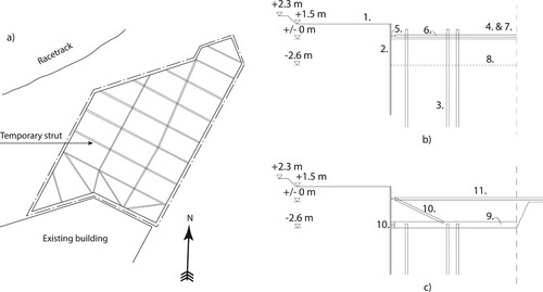
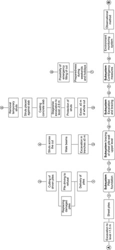
Figure 8. Block diagram of main functions and sub-functions of the proposed preliminary design solution.
At this point, we end this illustrative example of how a geotechnical engineer can create an understanding of and interpret the geotechnical context in the tendering of the foundation of a building. As a final comment we would particularly like to highlight how, among the risks identified with the proposed design solution, the risk associated with low and variable undrained shear strength of the clay can be treated. By applying the observational method (see further details on this method in Peck Citation1969; CEN Citation2004; Fuentes, Pillai, and Ferreira Citation2018; Spross and Larsson Citation2019; Spross, Bergman, and Larsson Citation2021; Powderham and O’Brien Citation2020), the excavation works can be better monitored and controlled. For example, the excavation can be performed stepwise, starting with the least sensitive part of the pit. This allows observation of the structural behaviour of the walls with prepared monitoring plans, while the risk for damage to the surroundings is kept to a minimum: in case predefined thresholds are exceeded, predefined contingency actions shall be put into operation to prevent damage. In such a technically advanced case, extensive quality assurance is essential. This implies the application of the observational method, involvement of an external expert review board, and an on-site organisation of geotechnical engineers to supervise the works.
4.5. The equestrian sports centre – what happened in reality?
The presented illustrative example was inspired by a real case from 1992. As we discuss in a previous paper (Spross et al. Citation2015), the excavation for the basement of the new office wing caused a substantial failure of the sheet-pile wall, causing large deformation in the clay so that a 10 cm wide crack developed on the racetrack, as well as an 0.5 m heave of the bottom of the excavation. The consequences of the failure meant that the excavation works had to be stopped and re-designed with dry deep mixing columns to stabilise the soil, which naturally caused a substantial cost increase. Moreover, the racetrack had to be taken out of service for some time, while the effects of the failure were dealt with.
According to the subsequent investigation, the failure had occurred because the overall stability of the excavation was too low and the contractor's design did not consider the complex geotechnical conditions at the site. On the other hand, the tender documents had stated a slightly higher undrained shear strength for the area than the additional investigations that were performed afterwards showed. Likely, neither the client nor the contractor had been aware of the local consolidation caused by the previously removed fill for the old public stand, even though it could be seen clearly on older maps.
It is our firm belief that applying the modern risk management procedures that we discuss in this paper would have helped in understanding the challenging geotechnical context at the equestrian sports centre, if such procedures had been readily available and common practice at the time.
5. Concluding remarks
The purpose of this paper is to provide practising geotechnical engineers and related professionals with risk management tools for their everyday work. As we see it, it is the practising engineers’ responsibility to manage the risks that come with their work – because there is no one around who does this better. A fundamental issue is that the engineer gains a good understanding of the situation at hand, i.e. the technical system, that the geotechnical engineering project presents. A key skill is to be able to identify the objectives of the project and any external factors that may affect the possibility of achieving these objectives.
By seeing the achievement of the objectives as the goal of the project, the connection to the general risk definition “effect of uncertainties on objectives” becomes clear, and so does the engineer's task: to identify, analyse, and evaluate how and to what degree the external factors affect the possibility to satisfy the required quality in the defined objectives. Well-performed risk management implies that this work is performed in a structured way, as a part of the engineer's everyday work. We believe that this in the long run ensures high quality in the performed engineering tasks.
Disclosure statement
No potential conflict of interest was reported by the author(s).
Additional information
Funding
References
- Aven, T. 2008. Risk Analysis: Assessing Uncertainties Beyond Expected Values and Probabilities. Chichester: Wiley.
- CEN. 2004. EN 1997-1:2004 Eurocode 7: Geotechnical Design – Part 1: General Rules. Brussels: European Committee for Standardisation.
- Essex, R. J. 1996. “Means of Avoiding and Resolving Disputes During Construction.” Tunnelling and Underground Space Technology 11 (1): 27–31. doi:https://doi.org/10.1016/0886-7798(96)00048-X.
- Fuentes, R., A. Pillai, and P. Ferreira. 2018. “Lessons Learnt from a Deep Excavation for Future Application of the Observational Method.” Journal of Rock Mechanics and Geotechnical Engineering 10 (3): 468–485. doi:https://doi.org/10.1016/j.jrmge.2017.12.004.
- Gransberg, D. D., M. Loulakis, A. Touran, G. Gad, K. McLain, S. Sweitzer, D. Pittenger, I. C. Nova, R. T. Pereira, and M. Pinto-Nunez. 2018. Guidelines for Managing Geotechnical Risks in Design–Build Projects. Washington, DC: Transportation Research Board.
- Gransberg, D. D., and R. M. Tapia Pereira. 2016. “Alternative Technical Concepts: A Geotechnical Risk Management Tool.” Journal of Structural Integrity and Maintenance 1 (1): 43–49. doi:https://doi.org/10.1080/24705314.2016.1153342.
- Hatem, D. J. 1998. “Geotechnical Baselines: Professional Liability Implications.” Tunnelling and Underground Space Technology 13 (2): 143–150. doi:https://doi.org/10.1016/S0886-7798(98)00041-8.
- ISO. 1994. ISO 8402: Quality Management and Quality Assurance – Vocabulary. Geneva: International Organization for Standardization.
- ISO. 2005. ISO 22476-2:2005. Geotechnical Investigation and Testing — Field Testing — Part 2: Dynamic Probing. Geneva: International Organization for Standardization.
- ISO. 2017. ISO 22476-10. Geotechnical Investigation and Testing — Field Testing — Part 10: Weight Sounding Test. Geneva: International Organization for Standardization.
- ISO. 2009. ISO 31000: Risk Management – Principles and Guidelines. Geneva: International Organization for Standardization.
- Olsson, L., J. Spross, S. Hintze, H. Stille, and O. Båtelsson. 2019. Verktyg för hantering av geotekniska risker: vägledning till systemförståelse och riskidentifiering [Tools for Management of Geotechnical Risks: Guidelines for System Understanding and Risk Identification]. Stockholm: SBUF.
- Paté-Cornell, E. 2012. “On “Black Swans” and “Perfect Storms”: Risk Analysis and Management When Statistics are not Enough.” Risk Analysis: An International Journal 32 (11): 1823–1833. doi:https://doi.org/10.1111/j.1539-6924.2011.01787.x.
- Peck, R. B. 1969. “Advantages and Limitations of the Observational Method in Applied Soil Mechanics.” Géotechnique 19 (2): 171–187. doi:https://doi.org/10.1680/geot.1969.19.2.171.
- Phoon, K.-K. 2017. “Role of Reliability Calculations in Geotechnical Design.” Georisk: Assessment and Management of Risk for Engineered Systems and Geohazards 11 (1): 4–21. doi:https://doi.org/10.1080/17499518.2016.1265653.
- Powderham, A., and A. O’Brien. 2020. The Observational Method in Civil Engineering: Minimising Risk, Maximising Economy. Abingdon: CRC Press.
- Ramasesh, R. V., and T. R. Browning. 2014. “A Conceptual Framework for Tackling Knowable Unknown Unknowns in Project Management.” Journal of Operations Management 32: 190–204. doi:https://doi.org/10.1016/j.jom.2014.03.003.
- Sartain, N., J. Mian, and M. Free. 2015. “Presenting Uncertainty Clearly: Challenges in Communicating Geotechnical Risk.” In Proceedings of the 5th International Symposium on Geotechnical Safety and Risk (ISGSR), edited by T. Schweckendiek, A. F. Van Tol, P. Pereboom, M. T. Van Staveren, and P. M. C. B. M. Cools, 739–744. Amsterdam: IOS Press.
- SGF. 2017. Risk Management in Geotechnical Engineering Projects – Requirements: Methodology. Report 1:2014E. 2nd ed. Linköping: Swedish Geotechnical Society.
- SGI. 2013. Effektivare markbyggande. Förslag till handlingsplan 2013-2016 [More Efficient Geotechnical Construction. Proposal for Action Plan 2013–2016]. Linköping: Swedish Geotechnical Institute (SGI).
- Smith, R. E. 2008. “An Evolving View of Geotechnical Engineering – a Focus on Geo-Risk Management.” In GeoCongress 2008: Geosustainability and Geohazard Mitigation, edited by K. R. Reddy, M. V. Khire, and A. N. Alshawabkeh, 231–238. Reston, VA: American Society of Civil Engineers.
- Spross, J., N. Bergman, and L. Larsson. 2021. “Reliability-based Verification of Serviceability Limit States of dry Deep Mixing Columns.” Journal of Geotechnical and Geoenvironmental Engineering 147 (3): 04020183. doi:https://doi.org/10.1061/(ASCE)GT.1943-5606.0002458.
- Spross, J., and S. Larsson. 2019. “Probabilistic Observational Method for Design of Surcharges on Vertical Drains.” Géotechnique (in press). doi:https://doi.org/10.1680/jgeot.19.P.053.
- Spross, J., L. Olsson, S. Hintze, and H. Stille. 2015. “Would Risk Management Have Helped? – A Case Study.” In International Symposium on Geotechnical Safety and Risk 2015, edited by T. Schweckendiek, A. F. Van Tol, P. Pereboom, M. T. Van Staveren, and P. M. C. B. M. Cools, 745–751. Amsterdam: IOS Press.
- Spross, J., L. Olsson, and H. Stille. 2018. “The Swedish Geotechnical Society’s Methodology for Risk Management: a Tool for Engineers in Their Everyday Work.” Georisk: Assessment and Management of Risk for Engineered Systems and Geohazards 12 (3): 183–189. doi:https://doi.org/10.1080/17499518.2017.1416643.
- Spross, J., H. Stille, F. Johansson, and A. Palmstrøm. 2020a. “Principles of Risk-Based Rock Engineering Design.” Rock Mechanics and Rock Engineering 53: 1129–1143. doi:https://doi.org/10.1007/s00603-019-01962-x.
- Steen, R., and T. Aven. 2011. “A Risk Perspective Suitable for Resilience Engineering.” Safety Science 49 (2): 292–297. doi:https://doi.org/10.1016/j.ssci.2010.09.003.
- Stille, H. 2017. “Geological Uncertainties in Tunnelling – Risk Assessment and Quality Assurance.” In Sir Muir Wood Lecture 2017. Paris: International Tunnelling and Underground Space Association.
- Stille, H., R. Sturk, and L. Olsson. 1998. “Quality Systems and Risk Analysis—New Philosophies in Underground Construction Industry.” In Proceedings of the International Congress on Underground Construction in Modern Infrastructure, edited by T. Franzen, S.-G. Bergdahl, and A. Nordmark. Rotterdam: CRC Press. Accessed July 15, 2019. http://www.befoonline.org/UserFiles/Archive/138/Rpt44.pdf#page=14.
- Taleb, N. N. 2007. The Black Swan: The Impact of the Highly Improbable. New York: Random House.
- Tonks, D., E. Gallagher, and I. Nettleton. 2017. “Grounds for Concern: Geotechnical Issues from Some Recent Construction Cases.” Proceedings of the Institution of Civil Engineers – Forensic Engineering 170 (4): 157–164. doi:https://doi.org/10.1680/jfoen.17.00008.
- van Staveren, M. T. 2006. Uncertainty and Ground Conditions: A Risk Management Approach. Oxford: Butterworth-Heinemann.
- van Staveren, M. T. 2009. “Extending to Geotechnical Risk Management.” Georisk: Assessment and Management of Risk for Engineered Systems and Geohazards 3 (3): 174–183. doi:https://doi.org/10.1080/17499510902788835.
- van Staveren, M. T. 2013. “Geotechnics on the Move: Guidance for a Risk-Driven way of Working.” Georisk: Assessment and Management of Risk for Engineered Systems and Geohazards 7 (3): 225–236. doi:https://doi.org/10.1080/17499518.2013.803370.
- van Staveren, M. T., and J. G. Knoeff. 2004. “The Geotechnical Baseline Report as Risk Allocation Tool.” In Engineering Geology for Infrastructure Planning in Europe: A European Perspective, edited by R. Hack, R. Azzam, and R. Charlier, 777–785. Berlin, Heidelberg: Springer Berlin Heidelberg.
- Wucker, M. 2016. The Gray Rhino: How to Recognize and Act on the Obvious Dangers We Ignore. New York: St. Martin’s Press.