?Mathematical formulae have been encoded as MathML and are displayed in this HTML version using MathJax in order to improve their display. Uncheck the box to turn MathJax off. This feature requires Javascript. Click on a formula to zoom.
Abstract
We provide relevant math and detailed sewing instructions for constructing a toroidal scarf that reverses three ways and whose design uses the unique inversion properties of a particular torus geometry and particular 3-component link. We explain how the scarf’s sewing instructions are guided by the mathematics underlying its construction.
GRAPHICAL ABSTRACT
Introduction
In Baker et al. (Citation2020), we described the evolution of an ‘infinity scarf’ design that is reversible not just two ways, but three! While that paper describes a progression of insights and theory behind the scarf design, it provides only broad-brush strokes of a method to actually sew it. In this paper we review key insights from earlier papers, outline some additional mathematics relevant to the sewing construction, and offer detailed instructions for constructing the triply invertible scarf.
As described in Baker and Wampler (Citation2017), a toroidal scarf (called an ‘infinity scarf’ in fashion lingo) can be constructed by sewing together the opposite edges of a regular hexagon. This hexagonally based scarf has several useful properties from a fashion design perspective. First, it inverts to the same shape and proportions and thus can be made reversible. Shape invariance on inversion turns out to be the exception rather than the rule for a torus, depending on its proportions. For example, a long skinny torus sized like many commercial infinity scarves will invert to proportions more suitable for a giraffe’s neck than a human being’s (see Baker et al., Citation2021 for a video illustration of this)! Second, the scarf forms a Möbius-like twist that drapes nicely on the human figure. Finally, it folds flat into an equilateral triangle, enabling neat storage.
The nicest way to see all these neat features of the scarf is to try it out with fabric by cutting a regular hexagon out of cloth and sewing together its opposite edges, leaving a small inversion slit in one seam. Its shape invariance on inversion can then be demonstrated by noting that before and after inversion its folded equilateral triangle configuration is the same size and consists of the same six triangular layers of fabric joined at their edges in the same pairings.
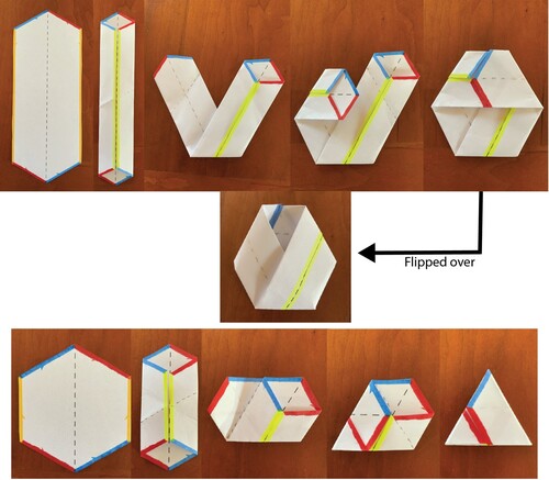
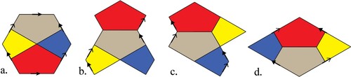
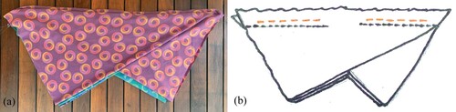
In Figure we also provide a paper construction. We show the construction first with an irregular hexagon (top left-to-right sequence) to make it easier to understand what’s happening when we perform the same sequence of folds on a regular hexagon. We start by folding the yellow edges (left and right on the hexagon) in toward the centre dashed line to connect them, resulting in a cylinder. Note that at this point, we can’t just directly connect the top and bottom of the cylinder, or the red edges (bottom left and top right on the hexagon) and blue edges (bottom right and top left on the hexagon) will not match up correctly. The remaining three folds create a half twist that correctly brings together the red-to-red and blue-to-blue edges, forming the torus. Flipping it over (Figure middle), we can easily see that it is both toroidal and, if the flattened cylinder form is viewed as a band, a Möbius band. The bottom sequence follows these same steps on a regular hexagon, only this time it produces the folded equilateral triangle configuration of the scarf (also shown rightmost in Figure ). Made from paper, it’s a little hard to see that this is likewise a torus and a Möbius band (in the flattened sense), but we can extrapolate from the top sequence to see that it is. However, to truly appreciate and see its toroidal form and nice Möbius-like drape, try sewing the same construction out of fabric (Baker, Citation2017)!
Figure 1. Connecting the opposite edges of an irregular (top and middle) and regular (bottom) hexagon: These paper hexagons are printed from the template in Appendix A, with the back edges coloured with markers to match the front edges.
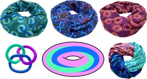
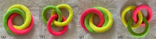
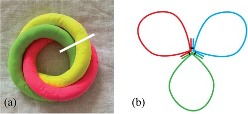
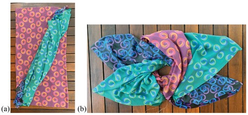
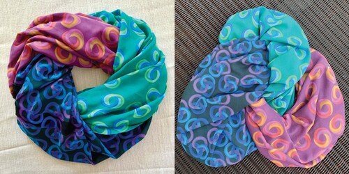
This scarf forms the basis for the three-way reversible scarf, which is composed of three such sub-scarves joined together in a link (see Figure a and 2b). In its wearable configuration, one torus in the link is inverted, causing the other two tori to wind up linked and nested inside it, as illustrated in Figure c (Baker et al., Citation2020). In our construction, the scarf has a double-slotted inversion slit that can be used to swap out which of the three toroidal surfaces is exposed on the exterior, thus facilitating the three-way reversibility. The resulting scarf retains almost all the nice features of its component tori. Only the flat folding is not entirely preserved because the linked tori on the interior don’t flatten, creating some puffiness. While it may require a little manipulation, the outer (exposed) torus can still be folded into an equilateral triangle, although it’s a bit like folding a puffy quilt.
Figure 2. a.) A selection of 3-component links from Robert Scharein’s (Citation1998–2022) Knot Zoo with the link (third from left), image used with permission. b.) A
link made of fabric tori. c.) X-ray vision drawing illustrating what happens when one torus (e.g. the purple one) in the link in Figure b is inverted.
In the sections below, we review key mathematical insights that gave rise to the scarf architecture, introduce some additional insights of relevance to the sewing construction, and provide a detailed method to make the scarf. Along the way, we explain how choices and decisions in our sewing construction are informed by geometric and topological considerations inherent in the design. Topics addressed include fabric pattern and type, cutting layout, seam location, order of sewing operations, and details of the link’s connection points.
Choosing fabric
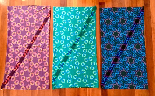
The first decision to make before sewing the scarf is about fabric: what type and what pattern. For a triply invertible scarf Ellie made for the Bridges 2020 Mathematical Art Exhibit, she designed three of her own fabric patterns (Baker, Citation2020). The sewing directions given here are illustrated using those fabrics. The fabrics are available on the fabric printing website Spoonflower (Citationn.d.) and include cutting and sewing guides. One printout (three are needed) fits on two yards of 54-inch wide fabric and the layout marked on it is appropriately scaled to the right size for a scarf. Outer bright white lines are cutting edges and inner (much paler) lines are sewing guides that create a 5/8-inch seam allowance. Each of the three fabrics requires two yards of Spoonflower chiffon with a ‘center’ repeat at 150 dpi.
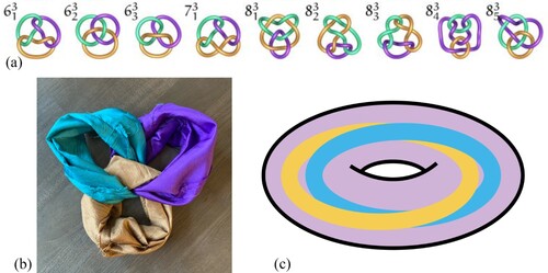
One motivation for designing special fabric for the scarf was to create a sort of self-referential pattern that would illustrate the mathematics of the scarf itself. Toward that end, the fabrics use motifs of the linked structure of the scarf, with each of the three fabrics showing the link in a different ‘pose’ (Figure a–c). The three ‘poses’ chosen are useful for understanding different aspects of the scarf’s properties (Baker et al., Citation2020), so in this way, the scarf serves as a teaching tool about itself. We will see later how one of these link configurations (Figure a) suggests a particular approach to making the scarf. Note that there are left- and right-handed orientations of the link and this one has opposite ‘handedness’ (in which the over-under crossings are swapped) from the
link in the Knot Zoo (Figure ). This is seen most readily by comparing the knot zoo image in Figure a to Figure d.
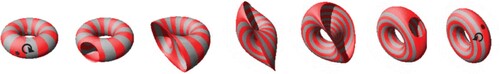
Figure 3. A clay link in different ‘poses'.
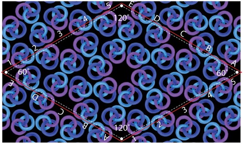
A second motivation for designing special fabric was to have patterns that echoed the hexagonal structure of the scarf. For this, the designs were created using a hexagonal tiling on the app iOrnament, which creates patterns from a selection of different tile types (Richter-Gebert, Citation2012). iOrnament will repeat any artwork drawn in the app using the selected tile type to create an infinite plane tiling. Quite helpfully, iOrnament also outputs a minimal rectangle that tiles the plane to produce the same pattern. This is useful because pattern printing sites (e.g. Spoonflower) typically require a rectangular image tile (as opposed to a triangular or hexagonal one) to fill the fabric plane. In this case, we repeated the iOrnament output tile in Adobe Photoshop to create a large enough rectangular swatch of the pattern to fit a full layout of the scarf, enabling the placement of cutting and sewing guides for printing directly on the fabric. Figure shows small swatches of the three fabrics.
Figure 4. Three fabrics illustrating the link in different ‘poses.'
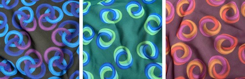
Not only is using a hexagonal tiling pattern a fun self-referential aspect to the design, but the particular tile type we chose (Heesch (Citation1968) Type TTTTTT) is based on a hexagon whose opposite edges correspond by translations, so it corresponds exactly to the sewing instructions for the hexagonal scarf, which are to sew together its opposite edges. Use of this tiling makes it possible to match the pattern at the seams when sewing it. The fabric pattern used was carefully scaled and the sewing guides placed to facilitate this matching. Continuity of the pattern at the seams felt important not just from a tailoring and craftsmanship point of view, but also to make the toroidal surface of the scarf appear infinite and unbroken to the proverbial ant travelling endlessly in loops along its surface in any direction.
Obviously, it’s also entirely fine to make the scarf with solid colours and commercially available fabrics. We mention the self-designing options and considerations only for those who might feel particularly adventurous about choosing a pattern with a meaningful relationship to the scarf’s geometry and topology.
A final consideration in choosing fabric is the weight and fibre type. Because the scarf is composed of a link with some bulk and layering to it, for wearability we recommend a very lightweight fabric. On the other hand, if you’re simply making a model for studying the mathematics and don’t care about how it feels to wear, you can use a heavier weight fabric, which is typically easier to work with. The Spoonflower chiffon we used has a weight of 1.5 oz. per square yard. For wearability, we recommend a fabric this weight or lighter. Spoonflower’s chiffon also has a particularly slippery texture that facilitates smoother inversions and enhances the tactile experience of swapping between surfaces.
Topology and geometry to guide our thinking
Before proceeding to the sewing directions, it will be helpful to outline some definitions and properties, both topological and geometric, that are particularly relevant to understanding what you are doing when sewing tori.
A topological torus is a stretchy shrinkable square whose opposite edges are understood to be connected or identified as shown in Figure . This same basic concept applied to fabric can be used to construct toroidal scarves by sewing together the opposite edges of a rectangle. However, a scarf made from fabric does not stretch or shrink in the topological sense, so its geometric properties become very important when sewing.
Figure 5. A topological torus: a stretchy shrinkable square whose opposite edges are understood to be connected.
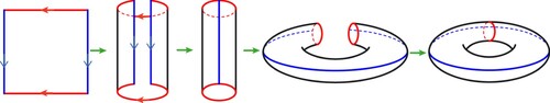
One aspect of the assembly in Figure should be noted. Assume that the square material is coloured differently on the front and the back, for example, white on the front and green on the back. In assembling the cylinder by identifying the blue (vertical) edges in Figure , one has two choices, as illustrated in the first two rows of Figure : One can form the cylinder so that the white side is showing outward, or so that the green side is showing outward. The result will be either a white or a green torus, even though the identifications are all the same! To help distinguish between these two possibilities, in addition to the colours, suppose that a small clockwise circle is printed on the interior of the square using penetrable ink so that it can be seen on both sides. If the circle appears clockwise when viewing the white side, then upon flipping the material over to view the green side, it will appear counterclockwise. Thus, one has the choice of assembling the torus with white on the outward side or green, which is equivalent to choosing the orientation of the circle one sees from the outside. Throughout this article, we will use the term ‘orientation’ in this sense; it should not be confused with the spatial orientation of the torus as embedded in three-space. (That is, we don’t care whether it is horizontal like a donut on a dinner plate or if it is tipped up on edge like a bicycle tire; we only care whether our directed circle appears clockwise or counterclockwise when viewed from outside.)
In topological terms, a torus is called an orientable surface because as we imagine sliding a clockwise circle around on it, moving its centre point around any closed loop, the orientation of the circle always returns the same as it left. This contrasts with nonorientable surfaces, such as a Möbius band or a Klein bottle, which contain loops where the circle returns to its original position with its orientation reversed. Consequently, our freedom to choose a white versus green construction can be restated as choosing a clockwise versus counterclockwise orientation, where we have arbitrarily chosen to associate white with clockwise.
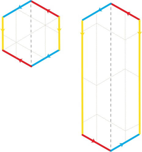
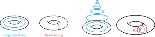
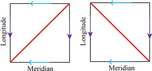
A torus embedded in three-dimensional space has loops called longitudes going around the torus hole and loops called meridians going through the torus hole (Figure left). While these definitions make intuitive sense to us viewing the torus in 3D, they have no inherent meaning in the two-dimensional topology of the torus, where a loop formed by a horizontal line wraps around onto itself in exactly the same fashion as a vertical line. One way to explain what happens topologically when the torus is embedded into 3D (without self-intersections) is to start by noting that it divides into three subsets: the torus surface itself, the interior of the torus, and the exterior of the torus. As shown on the right in Figure , a longitude is a loop on the torus that can contract to a point in the union of the torus and its exterior, whereas a meridian is a loop on the torus that can contract to a point in the union of the torus and its interior. These two classes of loops, which have no distinction in a flat torus model, play distinctly different roles once the torus has been embedded into three-space.
Figure 6. (left) A torus longitude and a torus meridian. (right) A longitude contracting to a point in the 3D exterior of a torus embedded in , and a meridian contracting to a point in the 3D interior of that torus.
Since we live in a 3D world, the distinction between meridians and longitudes becomes critical when we form a torus by sewing. If, as shown in Figure , the vertical edges of the square are first identified to make a cylinder, then they become the longitudes and, upon completing the construction, the horizontal edges become the meridians. Conversely, if the horizontal edges are first identified, then they become the longitudes and the vertical ones become the meridians. We thus have a choice in deciding which edges in the square cutout become meridians or longitudes. This can be seen in the first and third row of Figure . Note that the starting point in the third row is a rotation of the starting layout of the first row. This rotation doesn’t change the colour, and consequently doesn’t change the clockwise orientation of the starting layout. We will explain other aspects of Figure shortly.
Figure 7. Exploring the impact of different choices in the construction. Note that the meridians in the three leftmost columns are horizontal and in the three rightmost columns the meridians are vertical. The gold diagonals in the leftmost column correspond to the gold paths in the rightmost column.
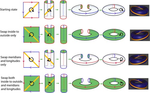
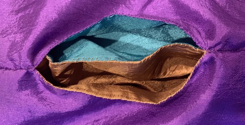
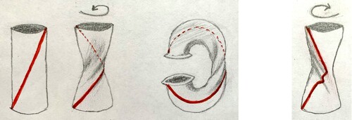
Once we have sewn a fabric torus in 3D, there is an additional way we can manipulate it: by leaving a small slit in one seam, we can turn it inside out through the slit. This action invokes a curious property of tori (at least to non-topologists): its meridians and longitudes swap roles—with the longitudes becoming meridians and vice versa, as illustrated in Figure . This role-swapping is precisely what causes many commercially available infinity scarves (i.e. those with long longitudes and short meridians) to dramatically change shape on inversion. Obviously, this has important practical implications for the viability of a reversible toroidal scarf.
Figure 8. When a torus is inverted through a hole, the longitudes and meridians swap roles (Surot, Citation2008).
As already noted, the swapping of meridians and longitudes can also be achieved by altering the assembly procedure of the square layout, as depicted in rows one and three of Figure . But this is not the same operation as inverting through a slit, because inversion swaps which colour shows, whereas rows one and three of Figure both give white tori.
Our ultimate objective—making a three-way invertible scarf—makes use of the concept of a torus knot. A torus knot is a closed path on the torus. Since it is closed, it must circle an integer number of times in each of the meridian and longitudinal directions, so an (
) torus knot,
, wraps around the meridian
times and around the longitude
times. Any loop that fails to completely wrap in either direction is a
knot, recognizable as a loop that can contract to a point while staying on the torus surface. By definition, meridians are type
and longitudes are type
. If we do not assign a direction of travel around the loop, then knots of type
and
would be considered identical types, and we can always normalize to make
. However, it is important to note that
knots and
knots are different types.
A torus knot is the image of the diagonal of slope 1 in the layout on the white side, assuming that the white side is showing outwards and horizontal lines are assembled to become meridians (as in Figure , first row). The knot with slope
in the layout on the white side is the
knot, when the white side is showing and horizontal lines are assembled to become meridians (as in Figure , row 3). When we specify the slope of the curve in the square layout, it will always be assumed that the horizontal axis will become a meridian and the vertical axis will become a longitude. This same diagonal of slope 1 on the white side has slope
when viewed from the green side. It follows that the same line in the square layout can form either a
torus knot or a
torus knot, depending on which side shows outward. (Compare rows 1 and 2, Figure ). Figure illustrates
and
knots on the torus.
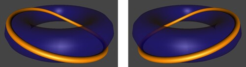
Figure 9. A torus knot (left) and a
torus knot (right) both traverse the surface of the torus meridianally exactly once at the same time as traversing it longitudinally exactly once.
Technically, a torus knot can meander and wiggle while making its traversals, but in our scarf construction, we will use shortest-path knots, which we illustrate using straight-line segments in Figure and elsewhere. When we move from topology to actual fabric constructions, a path on the fabric has a well-defined length, and straight-line segments drawn on the flat fabric layout become geodesics on the constructed torus.
Our three-way invertible scarf requires assembling three tori with seams that follow knots, which must be either all type or all
. This is because the process of physically inverting the scarf works best when we sew the tori together along such a knot, helping the hidden sub-scarves to position nicely inside the outer one. The proper functioning of the three-way scarf depends on the following theorem.
Theorem 1:
If a torus is inverted using the method shown in Figure , then torus knots remain
torus knots on inversion. Likewise,
torus knots remain
knots.
Later, we will discuss more about how this property of a torus plays into our scarf construction, but first we give a proof. Figure illustrates how small differences in torus construction that might, at first glance, seem inconsequential, can nonetheless impact which of these knots is produced. For this reason, it’s necessary to be explicit about the difference between and
knots, and how they can be distinguished on a torus already embedded in 3D without reference to the method of constructing it. This is the subject we address next. To help the discussion, we first summarize several observations from our discussion so far.
Observation 1: The orientation of a torus depends on which side is showing outwards. When a torus is inverted as shown in Figure , the orientation on its surface is also reversed. (See the arrows on the torus surface in the left-most and right-most images.)
Observation 2: Consider a closed curve in the planar layout that becomes a knot upon embedding the torus into three-space. Consider an alternative assembly sequence that swaps orientation while preserving which direction in the flat layout forms meridians and which direction forms longitudes. This alternative assembly changes the closed curve from a
knot into a
knot. Similarly, the alternative assembly also transforms a
into a
. As illustrated in Figure , rows one and two, this means turning the fabric over from white to green before following the same assembly sequence thereafter.
In addition to an orientation, the torus embedded in 3D space has a natural distinction between longitudes and meridians. As already noted, the inversion of the torus shown in Figure swaps meridians and longitudes, as well as changing the orientation, as shown by the directed arrows on the torus surface in the left-most and right-most images. The same effect can be obtained by switching the order in which the two sides of a square layout are connected, and at the same time connecting the sides so that green instead of white is showing (compare rows one and four in Figure ). Restating and naming this important point, we have:
Observation 3: The torus inversion shown in Figure both swaps meridians and longitudes and reverses the side that shows outward. The same effect can be made by reversing the order in which the sides are connected in the square layout (to swap meridians and longitudes) while simultaneously performing the assembly so that the opposite side is showing outward.
These two structures, orientation, and the notion of longitudes versus meridians, suffice to distinguish between and
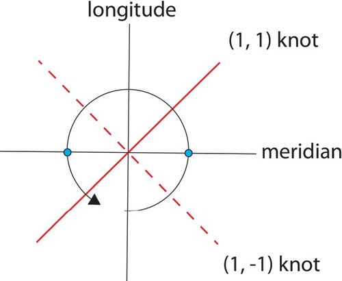
torus knots. To identify a knot on the embedded torus in Euclidean space, instead of on the planar layout, we can draw a small counterclockwise circle on the surface of the torus, as viewed from the outside, centred on any arbitrary point on the knot in question, as illustrated in Figure . This directed circle must intersect both the longitude and the meridian that go through its centre point. In fact, it intersects them each at two opposing points (marked in blue for the meridian in Figure ). From either meridian point, when following along the circle in the given direction, if the knot in question is crossed before crossing the longitude, then it is a
knot. If, on the other hand, the longitude is reached first, then the knot is a
knot.
Figure 10. Identifying a knot.
Having made these distinctions, some simple observations follow. First, if one reverses orientation (so that clockwise becomes counterclockwise, or green becomes white) but does not swap meridians and longitudes, then knots become
knots (see Figure rows one and two). Second, if one does not reverse orientation, but simply swaps longitudes and meridians, then
knots also become
knots (see Figure rows one and three). However, Observation 3 tells us that torus inversion both switches orientation and swaps longitudes and meridians at the same time (see Figure rows one and four).
Observation 4: The test in Figure shows that whether a knot is or
depends only on what are meridians and what are longitudes, and the orientation of the surface. Since the torus inversion switches both meridian and longitudes, and reverses orientation, the two effects cancel.
Theorem 1 is now a direct consequence of Observation 4.
We find the proof of Theorem 1 via Observations 1–4 to be illuminating in ways that have deepened our understanding of the often perplexing behaviour of these scarves and their toroidal inversions. However, experimentalists may prefer to confirm Theorem 1 with a simple sewing experiment. Either of the (1, 1) or knots depicted in red in Figure can be drawn on a square piece of fabric using a bleed-through marker, and the fabric may be sewn into a torus using the construction technique in Figure . The model can be inverted through a small opening left in one seam, and we can compare the results before and after the inversion to observe that there is no change in the direction of the knot. As we’ll see later, this inversion invariance of the (1, 1) and
knots is an important property that our scarf construction relies upon.
Figure 11. Flat tori with (1, 1) and (1, −1) torus knots drawn in red.
For the mathematically inclined, there is an alternative explanation for why torus inversion (as depicted in Figure ) switches meridians and longitudes, as well as orientation. We sketch the ideas here without many technical details one would need to form a proof. Consider the one-point compactification of 3D Euclidean space containing an embedded torus. The torus is now embedded in a 3D sphere , which is the union of two solid tori joined together at their common boundary, the embedded surface torus. In
, one of these solid tori is the exterior of the embedded torus, and the other one is the interior of the embedded torus. It is easy to distinguish meridians from longitudes in a solid torus because a meridian curve is contractible to a point in the interior of the solid torus, whereas longitudes are not. The meridians of the exterior solid torus are the longitudes of the interior solid torus and vice versa. There is a diffeomorphism of
onto itself that exchanges the exterior solid torus with the interior solid torus. This map turns the embedded torus inside out, reversing its orientation as well as switching meridians and longitudes.
Geometry and topology to guide our sewing
Returning to the issue of how to sew a torus, recall that a fabric cylinder can be sewn into a torus by joining together the cylinder ends. As we have seen with the paper construction in Figure , just like a square layout, the hexagon layout also involves first constructing a cylinder, and then joining its ends. There are two distinct methods for sewing together the ends of a fabric cylinder, which we’ll refer to as the ‘Flange’ and ‘Cuff’ methods, as depicted in Figure .
Figure 12. The Flange and Cuff methods for sewing a cylinder into a torus.
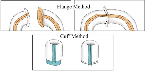
Observation 5. Joining a cylinder’s ends to form a torus using the Flange method makes the newly sewn seam a meridian of the torus in its current inversion state, whereas joining the cylinder’s ends using the Cuff method makes the newly sewn seam a longitude of the torus in its current inversion state.
As we’ve seen in the discussion of Figure , which seams on the finished scarf are longitudes, and which are meridians, depends on the construction procedure and is not a fixed property of the layout. Observation 5 is another example of this phenomenon. In general, when we talk about connecting the opposite edges of a fabric layout, we mean that we will be using the strategy depicted in Figure . Our construction approach for closing cylinders into tori uses only the Flange method. Substituting the Cuff method in our instructions will not produce the same result.
At this point, we have switched from talking about a ‘rubber-sheet’ torus, where only topology counts, to a fabric torus where the surface is inextensible and so distance has meaning. One of the key properties needed for the sub-scarves used in the triply invertible scarf is that they do not change shape when inverted. This is needed because, in the triply invertible scarf’s wearable configuration, the sub-scarves will be nested inside one another, with two of the scarves on the interior inside-out, and one on the exterior right-side-out. With every inversion, the exterior scarf swaps places with one on the interior. So, they must nest nicely together regardless of whether they are inside out or right-side out. Being the same shape regardless of their inversion status helps accomplish this. If they are not the same shape, the resulting problems can be akin to attempting to dress a short stout man in a tall thin man’s clothes, or vice versa.
Observation 6. A regular hexagon can be sewn into a torus that is shape-invariant on inversion by connecting its opposite edges using the method shown in Figure .
This key result from Baker and Wampler (Citation2017) depends on the fact that the hexagon-based torus has meridian geodesics the same length as its longitudinal geodesics. Shape invariance on inversion can be confirmed experimentally on fabric using the construction in Figure and a slit for inversion. We chose the hexagonally based scarf as the basis for the triply invertible scarf specifically because it has this property, as well as other qualities discussed in the introduction. However, as we’ll see next, we’re not restricted to sewing the sub-scarves from a hexagon. Other layout options that produce an equivalent scarf are possible.
Theorem 2:
A rhombus with its opposite edges connected is equivalent to the regular hexagon with its opposite edges connected, forming the same scarf once sewn.
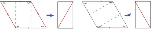
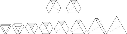
Figure illustrates this equivalency, showing how a hexagon (whose three sets of opposite edges are understood to be pairwise connected) can be transformed into a rhombus (whose two sets of opposite edges are understood to be pairwise connected), forming the same scarf. By relocating sections of the hexagon in such a way as to preserve its area and edge connectivity rules, we can produce the rhombus. Since the hexagon’s top and bottom edges are understood to be connected, we can legitimately relocate the red section of the hexagon shown in Figure a directly up without disrupting that connectivity, resulting in Figure b. Likewise, the yellow and blue sections can then be relocated up and to the right and left respectively to produce Figure c and 13d, resulting in a 60rhombus (13d). The torus can be sewn from the rhombus by stitching together its opposite edges, and the finished scarf will have the exact same geometry as one made from the hexagon. Only the seam lengths and locations are different.
Figure 13. Transforming a hexagon layout (a) to an equivalent rhombus layout (d).
On a rhombus, sewing together one set of opposite edges forms a cylinder with a diagonal seam as shown in Figure . The choice of which opposite edges are sewn determines the direction of the diagonal on the cylinder. A paper rhombus works well to demonstrate this by folding along the dotted lines in Figure . We will also see it demonstrated (three times!) in fabric when sewing the triply invertible scarf.
Figure 14. A rhombus forms a cylinder with a diagonal seam when either set of opposite edges is connected. The dotted lines represent valley folds in this diagram.
Since the rhombus layout is equivalent to the hexagon, it likewise produces a toroidal scarf that has a Möbius-like half twist as shown in Figure and Figure (Baker & Wampler, Citation2017). But since it’s not technically a Möbius band (unless you imagine the torus as flattened into a band), we refer to it as Möbius-like to avoid confusion. Once the rhombus’s first set of opposite edges are sewn together to form the cylinder, one end of that cylinder is given a half twist to correctly line up its second set of opposite edges for sewing the second seam. It is this half twist that gives the scarf its Möbius-like character. However, there are two choices for the direction of that twist, clockwise or counterclockwise. Either twist produces a correct scarf with the desired shape-invariance properties, but the two different twist options produce scarves that are mirror images of one another (e.g. Figure top). One reason we need to attend to the direction of the twist is again due to the nesting requirements of the design. If all three sub-scarves do not have the same twist, the resulting problems are akin to attempting to put a right-handed glove on a left hand, or vice versa. As we’ll see later, there is also another reason we’ll want to pay attention to the direction of this twist.
Figure 15. Two Möbius bands with mirror image twists. (top) A progression showing how a flattened Möbius-like scarf made from a torus can, with an increase in one dimension, result in the hexagonally based scarf, which folds into a 6-layer equilateral triangle. (bottom)
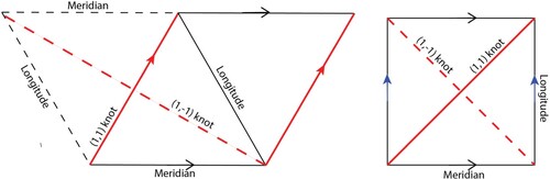
On the scarf made from the rhombus, unlike a scarf made from a square layout, the meridians and longitudes are not at right angles to one another. As a result, and
knots on a particular rhombus scarf are not the same length and are not mirror images of one another, at least not in the geometric sense. Figure shows example meridians, longitudes, and knots on the rhombus layout (left) in comparison to the square layout (right). Although there are multiple ways to sew the rhombus layout, we will be sewing it such that it matches the lefthand picture in Figure , with the
knot running along one edge.
Figure 16. Meridians, longitudes, and
knots on the rhombus and square layouts. To show the (1,−1) knot unbroken on the rhombus layout, it is presented on an alternate layout that includes the dashed triangle, in which case the (1,1) knot runs along a centre diagonal instead of an edge.
Our final observation in this section addresses another important property that both impacts how the scarf functions and provides a key sewing trick.
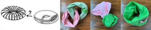
Observation 7. Two linked fabric tori become nested when one of them is inverted (Baker et al., Citation2020).
This observation is best verified experimentally as shown in Figure . It is a direct result of the swapping of meridians and longitudes on inversion, and it gives rise to an important sewing technique that makes it easy to hide seam flaps on a reversible toroidal scarf made from two separate layers of fabric. We can’t hide seam flaps by stuffing one torus inside the other to nest them back-to-back because the torus hole gets in the way (Figure left). But we can sew them inside out and linked and then invert one torus to get the same result (Figure photos). Note that in the linked configuration in Figure , the longitudinal rings of one torus are circling the meridian rings of the other, and vice versa. After inverting one torus, the former longitudes (now meridians) are still circling the meridians of the other torus. Likewise, the former meridians (now longitudes) are still circling the longitudes … and voila—nesting! The triply invertible scarf uses the more complex 3-component link shown in a and 2b, and we are nesting not a single torus, but a pair of linked tori. However, the same basic operation is applied.
Figure 17. Nesting two tori can be accomplished by sewing them linked and then inverting one.
The properties described in these last two sections come into play in the construction of the triply invertible scarf, and we’ll refer to them in the context of the sewing instructions in the following sections. An overriding goal to keep in mind, as we proceed with assembling the three component scarves, is that they must all be precisely identical to one another. All seams, twists, and knots that we construct in the process of sewing need to be identically aligned. Subtle differences in sewing steps—such as which set of opposite edges is sewn first, or which type of closure method to use—can produce surprisingly different results. Paying careful attention to the details is important to avoid mistakenly winding up with a construction that does not function as intended.
Rhombus layout benefits
Observation 6 says that we can sew together the opposite edges of a regular hexagon to create a toroidal scarf that does not change shape when inverted. Although a regular hexagon is this scarf’s quintessential layout (which we define as one with the shortest possible total seam length), this same scarf can be cut and sewn from infinitely many equivalent layout shapes (Baker & Wampler, Citation2017). As noted in Theorem 2, and shown in Figure , one such equivalent layout is the rhombus. The shape-invariance on inversion of the hexagon is a critical feature for the triply invertible scarf, but we’ll accomplish it using the equivalent rhombus layout instead. We will make three such (geometrically) identical scarves out of rhombi to link together into the link.
Despite its slightly longer total seam length (Baker & Wampler, Citation2017), the rhombus has multiple advantages for our project. One of them—that the hexagon does not have—is that it can easily be positioned on the fabric so that all its edges are cut on the bias. A bias cut is a cut that is diagonal to the direction of the fabric warp and weft, where warp refers to the threads running lengthwise and weft to the threads running crosswise in woven fabric. Typically warp and weft are perpendicular to one another. As any sewing manual will attest, seams cut on the bias have a greater degree of stretch and flow compared to those whose edges are cut perpendicular to the warp and weft.
With warp and weft oriented in the horizontal and vertical directions, Figure shows how to orient the rhombus such that all its edges are cut on the bias. While the rhombus geometry does not permit cutting these seams at a perfect 45-degree diagonal to the warp or weft, if the layout is positioned as shown in Figure , all the seams do have the same angle. This is helpful when sewing two edges of a seam together, since edges cut at differing angles can stretch differently from one another, making it trickier to match them up neatly at the join.
Figure 18. Laying out the rhombus on example fabric. The dotted white lines are sewing guides and the outer red lines are cutting guides that allow for a 5/8th inch seam allowance.
Do not be tempted to minimize sewing waste by rotating the rhombus away from the configuration shown in Figure , as doing so will not produce equivalent bias cuts on all the seam edges. Once sewn, the dots at the four corners all come together to form a single point on the finished torus. This point is the intersection of the two seams we will be sewing on each sub-scarf. Those corner points should be clearly marked front and back on your layouts, as this will make it easier later to ensure the seams intersect at (and are not sewn beyond) them. The numbers and letters in Figure are example markings that can also be made inside the seam allowance at regular intervals, using an erasable sewing marker, to indicate how to connect matching points along the opposite edges. This makes it easier to accurately line up edges horizontally for sewing the seam. However, if your fabric has a hexagonally based pattern that has been engineered to match at the seams, these markings may not be needed because the pattern itself will indicate the correct join points. For example, if you print and cut out the rhombus in Figure on paper and fold it into a cylinder using the method illustrated in Figure , the pattern will match perfectly without distortion only if you join it correctly along the dotted white lines. We printed faint stitching lines on our Spoonflower fabric, which, combined with looking at the pattern, help to match it accurately at the seam. Really precise matching takes care, however.
Note that the rhombus also has the nice features that it requires only two seams (thus fewer than a hexagon) and that both are the same length (thus it has more symmetry than, say, an equivalent rectangular layout). A scarf-appropriate size for the rhombus is a 40-inch side length (the dotted white sewing edges in Figure ).
Practical problems
Before discussing an even more important reason why the rhombus is useful, we need to detour briefly to explain some practical problems that can occur with the triply invertible scarf design. Its construction entails sewing the three slitted fabric tori into a link while they are inside out. Technically, the slits and tori don’t have to be aligned in any way. To transform the scarf, you could invert any one torus you choose, let’s say green. To change colours, you invert back again, then choose, say, a purple one and invert it. There are two downsides to this method: 1) it requires two inversion motions to change colours and exposes the
linked state in between (which otherwise might be used as a place to hide the fabric backsides and raw seam edges), and 2) the two nested hidden tori don’t necessarily stay distributed nicely around the torus tunnel. They must go around it, but with link components free-floating with respect to one another, the fabric can bunch up in some areas and stretch tight in others. This can create the need for tugging and smoothing after an inversion.
To solve (1), we want to align the slits and sew them together as one compound double-slotted slit (Figure ). This way, when you reach through the purple torus’s slit to grab green fabric, you are also reaching through the green torus’s slit and you accomplish the two inversions in one motion, thereby swapping the position of those two tori without ever re-entering the link state. To solve (2), we want to limit the free-floating nature of the link by attaching the three tori together as much as possible to provide stability during inversions.
Figure 19. A double slotted inversion slit.
More rhombus benefits: engineering a (1, 1) torus knot seam
We can use a torus knot positioned along the same seam of all three tori to help with both problems outlined in the previous section. A key benefit of the rhombus layout (in addition to enabling bias cuts) is that it provides a seam that can be made to form a (1, 1) torus knot on each of the three individual tori. Recall that a
torus knot is a path on the surface of a torus that traverses it meridianally exactly once at the same time as traversing it longitudinally exactly once. Because the torus meridians and longitudes swap roles on inversion, if we place a slit along a longitudinal line, it will change to being on a meridian after the torus is inverted, and vice versa. Given this chameleon-like repositioning of the meridians and longitudes, and the need to repeatedly swap the inversion states of the tori in our
scarf link, how can we manage to keep the three slits aligned regardless of inversion state? Our solution is to place them along the path of a
torus knot.
While meridians and longitudes swap on inversion, a (1, 1) torus knot is equal parts both. Since it traverses one meridian and one longitude, it will, after inversion, still traverse one longitude and one meridian (which is the same as traversing one meridian and one longitude). Furthermore, from Theorem 1, we know the knot won’t transform into a
knot—it reliably remains the same knot. So, the
knot is wonderfully stable—nothing about it changes when we invert the torus. Thus, the path of a
torus knot is an excellent location for aligning the slits. However, for the plan to work well, we need it to be possible to position the
link so that all three tori meet along an identical
torus knot on each. As it turns out, this is exactly their positioning in one of the link’s most wearable configurations.
To see this, we’ll inspect the link ‘pose’ shown in Figure b (and in Figure a), in which the whole link looks almost like a single compact torus with a clearly defined neck hole. In these solid clay models, the link is positioned here such that the three tori appear to touch each other along a single line, which would be a good place to connect them. But what is that line? A
link can be constructed by starting with a simple two-ring link and adding a third ring that links through both the other two. If we inspect the
torus knot depicted in Figure a, and imagine the yellow knot disconnected from the torus surface without cutting it, it becomes evident that the blue torus and yellow knot are a simple two-ring link. If you imagine adding a third ring going through these two, topologically, this two-ring link then becomes the
link. It turns out that the place where the three tori meet in Figure b is along a
knot on each. We can see this in the ‘filmstrip’ in Figure , which reveals the hidden line where the three tori meet to be a
knot on each.
Figure 20. a) A torus knot, shown in yellow on a blue torus. b) A clay model of a
link positioned so that its three component tori essentially ‘touch' each other along a
knot on each.
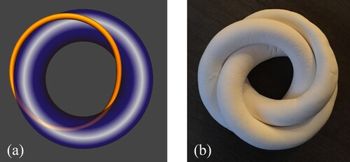
Figure 21. A clay model demonstrating that the hidden line where the three linked tori meet in Figure b coincides with a torus knot on each torus, shown in black.
Sticklers may note that the solid tori in our clay model have circular cross sections and since three circles cannot be made to touch one another at a single point, the clay tori do not actually touch each other at the knot. But since they are touching pairwise in a configuration that comes very close to a single touchpoint, and since our fabric tori can crease and fold a bit, coming close is sufficient. By slightly creasing each fabric torus along a
knot to change its cross section into a teardrop shape, as in Figure b below, one finds that it is indeed possible to make three fabric tori touch along a
knot. This then provides an excellent location to position and join the three slits because it remains so stable regardless of the inversion status of the three sub-scarves.
As you may already have guessed, the invariance of the knot on inversion can also be used to address our second problem: how best to attach the tori together to stabilize the whole link during inversions. In its wearable configuration, the scarf always has two tori in a linked configuration—albeit nested inside the third one, which surrounds them on the exterior. An inversion simply causes the outer torus to swap roles with one of the inner tori, allowing it to claim the exterior spot. Since the tori are continually moving back and forth between linked and nested states, we want a way to hold the three tori together that doesn’t impede this swapping action. Connecting the three scarves not just at the slits, but along the entire (or almost entire) (1,1) knot, helps secure them in the Figure b position. We’ve used this method successfully, and, although there is still some bunching up of the fabric during inversions, and smoothing out required after them, it’s a huge improvement over a totally free-floating link like Figure b. Perhaps an even better solution is possible, but this is the best practical solution we’ve found so far.
In the following instructions, we’ll see how to create a seam that follows the path of a knot, how to position the slits on it, and how best to attach the three tori together along it.
Sewing step 1: stitching the first pair of rhombus edges to create three cylinders
After cutting out the three rhombus layouts, the next step is to sew the first seam on each by stitching together one set of opposite edges, carefully making sure it’s the same set for each. If you’re not using fabric with a natural colour difference that identifies its front and back, it’s critical to assign and label the front and back, so that you can identify which is which later. To achieve consistency among the three rhombi, it’s helpful to place all three tori layouts as shown in Figure , with the opposite edge pairs marked as A and B as shown, indicating the A-pair is to be sewn first. If you are consistent in your sewing steps, it doesn’t actually matter which edge pair is chosen for the first seam. Either works, but as demonstrated on a square layout in Figure , the choice can impact which torus knot you get. It also ultimately impacts direction of the Möbius-like twist, which must be consistent among the sub-scarves, as well. For easiest comprehension if replicating this work, the crafting reader may want to match their work to the examples shown in Figure and Figure .
Figure 22. Sewing the first seam. Pressed open, its ends look like the close-up photo at right.
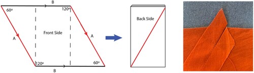
Figure 23. Sewing together the first pair of rhombus edges results in a ‘cylinder' with a diagonal seam. Each diagonal seam has a 4-inch opening in the middle.
It might seem confusing to visualize how opposite edges of a rhombus can be connected and sewn. However, if you start by pinning together the two sets of corner dots marked on the layout (i.e. the white dots in Figure ), it will come together like a normal seam. Do not stitch beyond those dots at either end.
Once the seam is sewn, you will have a cylinder (topologically) with a diagonal seam (Figure ). If you flatten the cylinder, the diagonal will appear to be leaning left or right, depending on which pair of opposite edges was sewn. One caution: a diagonal on a cylinder, unlike torus knots on a torus, will reverse direction when you invert the cylinder, so be sure your cylinder diagonals match Figure when they are inside-out.
When stitching this first (A) seam, leave a 4-inch opening in the middle for the slit. Don’t estimate the middle—measure it precisely, as correct positioning is important later for aligning the slits. These openings will eventually be part of the double-slotted inversion slit. If sewing a patterned fabric with an intent to match it at the seams, baste the seam by hand before machine stitching it to have better control over matching accuracy. Once sewn on the machine, pressing open the seam flaps creates less bulk when crossing over it with the next seam, and makes it easier to neatly finish the slits in the final steps. Pressed open, the sewn seam ends will look like Figure right. You should now have three cylindrical forms with slits in the middle of their diagonal seams, as shown in Figure .
This diagonal A seam will become a torus knot once the scarf is sewn, but it does not look like one yet because the diagonal travels only halfway around the meridian. When we form the cylinder into a torus by closing its ends (i.e. by connecting the B seams) we want the A seam to form a closed loop that makes one full longitudinal traversal and one full meridian traversal, i.e. the definition of a
knot. To accomplish this and match up the B edges properly, the cylinder will require a half twist at one end before sewing. A half twist in one direction transforms the A seam into a (1,1) torus knot, whereas a half twist in the other direction makes it a (1,0) knot, traversing the torus once longitudinally, but not at all meridianally. These correct and incorrect twist options are illustrated in Figure . Although we’re going to delay sewing this seam until a later step, it’s a good idea at this point to familiarize yourself with the two twist options and make sure you understand which one produces the correct result. This will make it easier to check for correctness and avoid mistakes later. Playing with your fabric cylinders and studying the examples in Figure should help.
Figure 24. If the cylinder end is rotated a half twist in the correct direction prior to sewing together the cylinder ends, the resulting torus will have a seam forming a knot. The sequence on the left illustrates a correct twist, with the knot depicted in red. An incorrect twist that forms a wiggly (1,0) knot instead is shown at right.
Sewing step 2: attaching at the  torus knot seams
Perhaps non-intuitively, our next step is to connect the cylinders together at the knot, i.e. along their A seams. Even though this seam is not yet a
torus knot, we know it will become one, and it’s easier to sew that connection now. You might reasonably wonder why we would do this step prior to connecting the cylinder ends (i.e. sewing the B seams) to form them into tori in a
link. Attaching the cylinders together along their
knot seams at this stage is easier because we can still lay these ‘knot-to-be’ seams along a straight line, whereas later, once they are twisted and closed into tori/knots, we must sew along curves.
Figure a shows a stack of the three cylinders positioned so that their knot seams are held together along a straight line. We have made scarves in which we simply machine stitched them together in this position right through the six layers of raw edging (leaving a gap at the slits), and this works okay. However, this approach has an asymmetric sandwiching of one seam inside the other two, which can be tactilely noticeable in the inversion symmetry of the finished scarf.
Figure 25. Sewing three tori together along the knot. a) A stack of three cylinders positioned so that their
knot seams are held (roughly) along the same straight line. b) A drawing showing this same stack with the pairwise stitching on the seam flaps (wide red dashes) magnified to provide a clearer view of how each pair is sewn.
More recently, we’ve gotten better results by stitching the raw edge flaps together in three pairwise seams. If we imagine the linked scarf sliced meridianally along the white bar in Figure a, with the three tori blown up like balloons, we get the cross-section view illustrated in Figure b, which illustrates how the seam flaps are sewn in pairs. The black stitching on the flaps in Figure b corresponds to the red stitching in Figure b. This approach has nice circular symmetry and corresponds more closely to the clay model positioning of the link shown in Figure b. A sewing machine could be used for these seams. But for better control, we chose to loosely hand sew them, stitching the three pairs together along their edge flaps about 1/8th of an inch from the machine-stitched A seam, as shown in Figure b in red. Since they will be hidden on the finished scarf, these seams don’t need to look perfect. For basting all three, we chose one colour of thread that contrasted enough to be seen easily (which is helpful later), but not so contrasting that it showed through the very sheer chiffon fabric.
Figure 26. a) Clay model with white cut line representing an imagined slice-through location to produce the cross-section illustration in (b). b) Cross-section view showing the seam flaps with pairwise stitching in black.
Important detail: leave the seam open (with about a half inch margin) along the slits and leave a one-inch margin at each of the two ends, as shown in Figure b. The margin at the ends is needed for seam allowance and maneuvering room later when you go to sew together the cylinder ends. The margin at the slits is needed so that you have some adjusting freedom later in case the slits don’t line up perfectly. After sewing one pairwise seam, you can flip one cylinder around the shared seam axis to be able to access and sew the next pair, kind of like the operation of a Rolodex. Sew all three pairs this way.
Note that by making the teardrops of Figure b narrower, this pairwise approach of attaching the tori together along the seam could be extended to any number of tori in your ‘Rolodex.’ This could be useful for anyone wanting to attempt a quadruply or quintuply invertible scarf or larger (we haven’t yet tried this; the reader is invited to be the first to climb that higher peak!).
Sewing step 3: stitching the second seams to create the knot and link
Now that all three tori are attached together at their knot seam, the next step is to connect the cylinder ends to form the three tori and
link. We highly recommend loosely hand basting these next seams prior to machine stitching, particularly if you’re matching a pattern at the seams. You’ll remove the basting once the machine stitching is done, so consider using a bright contrasting colour thread (we used white) that you can easily follow on the machine and easily see to remove later.
Connecting the cylinder ends of the first torus is trickiest because the cylinder needs that half twist at one end to join its other end properly, and a twist in the wrong direction will not create the knot. Here’s where prior familiarity with that topic is handy. Since the three cylinders are now like a set of conjoined triplets attached along their diagonal seams, things can get a little confusing, but it’s possible to bunch up two of the cylinders along the diagonal seam and try to ignore them, so that we can focus our thinking on just one cylinder, as shown in Figure a. Then we can apply the method illustrated in Figure to see how to correctly twist the first cylinder to form its
torus knot.
Figure 27. a) Two of the attached cylinders bunched up out of the way, to make it easier to focus on the third. b) The scarf with one cylinder correctly sewn closed.
To sew the seam, use the ‘Flange method’ (Figure ) to ensure, per Observation 5, that your new seam is a meridian. You’ll find that the knot seam where all three tori connect is an obstacle, but since we left a one-inch open margin there, you should be able to access the full circuit of the meridian seam as necessary, even with the machine. You will sew the seam into a complete closed loop to close the four corner points of the original rhombus so that they all connect and merge into a single point. Because of the two other tori attached near the vertex points, it works best to start sewing this loop at one corner point and finish at the other. It can be tight maneuvering, but the entire closed loop can be sewn and will wind up intersecting the other seam at the expected 60°/120° rhombus angles. Once the first cylinder is sewn closed, the other cylinders get forced into position to be sewn correctly and twist errors are harder to make.
After the first cylinder is closed, your scarf should look like the one in Figure b. Use the Flange method again to close the other two cylinders, double checking everything carefully as you go to convince yourself that the knots and
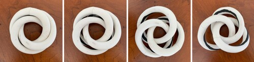
linkage are being formed correctly. Once all three tori are sewn closed, you should be able to locate the neck hole and position the scarf to look like the photos in Figure , where the structure of the
link can now be seen. At this point you can remove any unwanted basting, clip loose threads, and move on to the final step.
Figure 28. The resulting link after all three cylinders have been closed into tori.
Astute readers might observe that Figure (left) depicts a 4th potentially wearable state for the scarf, in which the link itself remains visible and no tori are nested. We have experimented with scarves that leave such a linked state accessible. While it’s a fun potential option, it introduces an extra layer of construction complexity. First, the raw seam edges are exposed in this configuration, so they would need to be finished off in some visually acceptable way, such as with French seams or a serger. Second, it’s only a viable option if the fabric backsides are attractive. Finally, it introduces additional questions about how best to architect a tidy slit to accommodate the fourth state. Adventurous readers might wish to try addressing these additional complexities, but, for the current project, our goal is to produce a scarf with just three symmetric inversion states and a double-slotted slit.
Sewing step 4: creating the double-slotted inversion slit.
If you have gotten to this point, congratulations! You’ve done the most difficult part. All that remains is to finish off the double slotted slit, which is easy. However, once you sew together all the slit edges pairwise, you will not be able to re-enter the linked state—so be sure to enjoy it, study it, and learn anything more you want from it before proceeding!
When ready, invert any one torus through its slit to enter the wearable state in which that torus is on the exterior and the other two are linked inside it (i.e. apply the method described in Observation 7). At this point, the scarf will be in the configuration illustrated in Figure c, and you should be able to confirm that all three torus slits are reasonably well-aligned. Figure (left) shows what they might look like. It’s possible that the slits may be slightly misaligned (despite your careful efforts earlier), but since we left inch margins along the
knots at the slits, you can still extend the opening of any (or all) of the slits up to an additional
inch at either end, as needed, to make sure they line up perfectly. About a five-inch slit was a good length for our fabric, but judge for yourself the length that works well for yours. Once you’re satisfied with the slit alignment and length, the six edges should be sewn together in appropriate pairs to create the double-slotted slit and close off any further access to the fabric back sides, raw edges, and linked state. We did this final step by hand using a whip stitch with different coloured thread on each pairing that matched the fabric on one side. Figure (right) shows the sewn slit.
Figure 29. The aligned slits, unsewn (left) and sewn (right), and the vertex joining the four corners of the rhombus (centre).

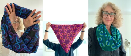
Once all three paired edges of the double slot are stitched closed, you’re done! Figure shows the finished product. Now that you have your own triply invertible scarf, you can practice the art of inverting it, smoothing it out after inversions, draping it nicely for wearing, folding it into an equilateral triangle for storing, and demonstrating it to your friends!
Figure 30. The finished scarf displayed, folded, and worn.
Conclusion
The triply invertible scarf is not a traditional museum artwork in the sense of a sculpture or painting you can simply view to enjoy or appreciate. It’s a tactile, wearable piece that is best played with, explored, inverted, and worn. While sewing one for yourself might not be for the faint-hearted, it’s currently the only way to acquire one—and doing so augments the experience, offering deeper understanding of its mathematical underpinnings and interesting structure. With the conviction that just seeing it is not enough, we’re excited to share our insights, sewing instructions, and our hope that others will adventure (and venture) with us down this entertaining path.
Acknowledgments
We would like to thank the editors and anonymous reviewers for their many helpful suggestions. The torus knot images in Figures 9 and 20 were produced using Robert Scharein’s KnotPlot (1998–2023), which is a marvellous tool. Thank you to Kent Christman for helping diagnose the misstep the first time Ellie tried to sew a torus knot seam on a rhombus layout, and for his excellent active listening in general.
Disclosure statement
No potential conflict of interest was reported by the author(s).
References
- Baker, E. (2017). Invertible Infinity II. Bridges 2017 Conference Art Exhibit. http://gallery.bridgesmathart.org/exhibitions/2017-bridges-conference/ellie-baker.
- Baker, E. (2020). Triply Invertible Toroidal Scarf. Bridges 2020 Virtual Conference Art Exhibit. http://gallery.bridgesmathart.org/exhibitions/2020-bridges-conference/ellie-baker.
- Baker, E., Baker, D., & Wampler, C. (2020). Infinitely invertible infinity. In C. Yackel, R. Bosch, E. Torrence, & K. Fenyvesi (Eds.), Proceedings of bridges 2020: Mathematics, Art, music, architecture, education, culture (pp. 83–92). Tessellations Publishing. http://archive.bridgesmathart.org/2020/bridges2020-83.html.
- Baker, E., Baker, D., & Wampler, C. (2021, April 20). Crafts, Math, and the Joy of Turning Things Inside Out, Gathering 4 Gardner Organization, Celebration of Mind talk. [Vídeo]. YouTube. https://www.youtube.com/watch?v=f82K5v8Ti7c&t=0s.
- Baker, E., & Wampler, C. (2017). Invertible infinity: A Toroidal fashion statement. In D. Swart, C. Séquin, & K. Fenyvesi (Eds.), Proceedings of bridges 2017: Mathematics, Art, music, architecture, education, culture (pp. 49–56). Tessellations Publishing. http://archive.bridgesmathart.org/2017/bridges2017-49.html.
- Heesch, H. (1968). Regulares Parkettierungsproblem. Westdeutscher Verlag. http://www.tessellations.org/tess-symmetry7.shtml.
- Richter-Gebert, J. (2012). iOrnament [computer software]. https://www.science-to-touch.com/en/iOrnament.html.
- Scharein, R. (1998–2022). Knot Zoo and Knotplot [computer software]. https://knotplot.com/zoo/ (As of January 23, 2020).
- Spoonflower. (n.d.). https://www.spoonflower.com/profiles/elliebaker.
- Surot. (2008, February 13). Turning a Punctured Torus Inside-out. Public domain, via Wikimedia Commons. Retrieved March 2, 2023, from .
Appendix A.
Templates for the paper constructions in Figure 1.