
 ?Mathematical formulae have been encoded as MathML and are displayed in this HTML version using MathJax in order to improve their display. Uncheck the box to turn MathJax off. This feature requires Javascript. Click on a formula to zoom.
ABSTRACT
Redox flow batteries (RFBs) are perceived to lead the large-scale energy storage technology by integrating with intermittent renewable energy resources such as wind and solar to overcome current challenges in conventional energy storage devices. Recently, several modifications have been employed in the development of RFBs to achieve efficient energy storage at an economically acceptable cost of the system. For large-scale deployment, further improvement in energy efficiency, longevity of the system, and reduction in cost are required. Most of the recent research activities are focused on the discovery of new materials to increase RFBs’ energy storage-release performance with long-term stable operations suitable for implementation in mobile devices. Considering the growth in research interest, and the volume of literature generated over the past decade on the topic, a review article highlighting the key development and status of research is essential. Herein, we intend to provide the basics of the RFB system including their cell components, various types, and the current trends highlighting the study gaps that require extra effort. Moreover, we conducted an analysis of the cost of the RFBs, associated challenges, and mitigation strategies. The review also includes electrode/electrolyte materials in a table format for quick access for comparison purposes.
GRAPHICAL ABSTRACT

1. Introduction
The fossil fuel-based energy resources, which were formed over a period of hundreds of millions of years, are being consumed in a short time period at an exceedingly rapid rate. At present, 20 × 103 TWh per year of energy is in demand that is growing at a rate of 3% per year (Citation1). Hydroelectric power plants, fossil fuels, and nuclear power plants are the primary sources of electricity, out of which, approximately two-third of the production of electrical energy is from fossil fuels (Citation2). The excessive use of fossil fuels has affected the carbon dioxide level in the environment that rapidly increased from 280 to 401 ppm in December 2015, which is seen as a central factor linked to adverse climate changes and increase in the global environment temperature (Citation3). The adverse effect of climate change on account of excess usage of fossil fuels has pushed the researchers and policy makers to develop and adopt energy systems with zero carbon emissions. Such systems are expected to be based on the utilization of renewable energy sources like hydroelectricity, solar energy, geothermal energy, wind energy, etc. Geothermal energy and hydroelectricity have limited availability due to the requirement of specific geographical conditions. Therefore, the solar energy and wind energy power stations are the promising alternatives for the future of power generation (Citation4).
A considerable number of solar and wind energy plants are proposed to be built at different locations in the world and between 2020 and 2050 to transition the energy dependency from fossil fuels to renewable sources (Citation4). The solar and wind power plants are considered as intermittent sources of energy because their productivity completely depends on the time and climatic availability, making them less suitable for uninterrupted use. However, energy storage systems/devices (ESSs) are seen as possible solutions to store the energy generated from solar/wind sources and release them at appropriate times to maintain continuous supply of energy (Citation5). Here, lead acid batteries, RFBs, fuel cells, lithium-ion batteries are the commonly used systems for storing energy. Lead acid batteries are the most used devices because of their low cost and ability to provide high currents to maintain a large power-to-weight ratio. + battery is also a similar system with reduced weight, however, requires a high cost. The RFBs can be used as the alternating renewable energy storage system for large-scale applications because of their outstanding performance at low cost. When compared with conventional batteries, the flow batteries have an attractive structure, unique scale-up characteristics and provide greater design flexibility. Among the many types of energy storage systems available in the market, RFBs are most suitable for large-scale applications based on their performance and design flexibility when compared to others. provides a quick comparative summary of the several types of energy storage systems for an easy access to the readers.
Table 1. Types of energy storage systems and their key features.
In principle, the RFB is a type of electrochemical cell which converts chemical energy into electrical energy. The chemical energy in the RFB is provided by the chemical reactions (reduction/oxidations) in the compounds dissolved in the electrolyte solution. The RFBs have some technical advantages over the conventional batteries. In conventional batteries, the activators and reactors are placed together, because of that the capacity of the conventional battery is limited and it cannot store large amount of energy. Whereas a distinction is made between the activators and reactors in RFB, two are separable, and the electrolytes are stored in different tanks. Also, the cell is divided by a membrane into two half cells. Therefore, the longevity of the battery is comparatively high, and the storage of energy is proportional to the storage tanks used for storing the electrolytes. There are different kinds of RFBs based on the types of components (electrode and electrolytes) used, which dictate their specification and performance. Out of various types of the RFBs, vanadium redox flow battery (VRFB) is widely accepted, which is considered as an industrial type of energy storage system owing to the higher energy density and long-term performance. Also, it is known to be more stable with long-life cycles than others (Citation15).
More recent reports suggest the use of organic materials as a good substituent for vanadium as an active material (Citation16). Some selected organic materials can be considered for a wide range of temperature applications as they do not induce precipitation issues especially at high temperatures. The cost of suitable organic materials can also be much lower than vanadium as they are widely available. Their functional properties such as redox reactivity, and capacity of aqueous organic RFBs are more attractive than VRFB (Citation16). As two electrons are involved in the redox reaction of organic materials, their capacity is twice as compared to the vanadium RFB where only one electron transfer is seen. These are some features of organic flow batteries that make them more promising, nonetheless, more research is still required in this emerging field for a large-scale deployment.
Iron and Mn–-based RFBs are also commonly used for energy storage in the solar and wind power grids (Citation17). In addition, the RFBs can be used in electric vehicles, load leveling and power quality control applications. All-vanadium and zinc-bromine systems are mainly applicable for these applications (Citation18). A 1-MWh/4-MWh zinc-bromine battery is known to be the first RFB installed in Imajuku, Fukuoka, Japan, in 1990 under the ‘Moonlight project’ sponsored by the Japanese government. A 15-kWh all-VRFB was the first VRFB system installed by the University of New South Wales as a demonstration of solar house in Thailand (Citation19). In power grid systems, the failure of electrical power can engender many challenges and requires a fast stabilization to avoid unforeseen problems. RFBs are more suitable for such situations as their response time to power demand can be less than 1 min. The suitability of RFBs for practical applications as energy storage systems can be easily understood by looking at their substantial growth after the first successful installation in the UPS application in 2001 by SEI (Citation20).
Organic redox flow batteries (ORFBs) are another important category of RFBs, providing favorable energy storage environment to harness the power of organic compounds and appropriately release electrical energy as required. In contrast to traditional inorganic RFBs, ORFBs utilize organic molecules as electroactive materials, opening new avenues for sustainable and cost-effective energy storage (Citation21). Nonetheless, in this study our focus is only on metal-based RFBs, and a separate ORFBs focused study can be considered in future to cover the development in this area.
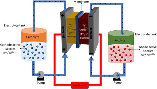
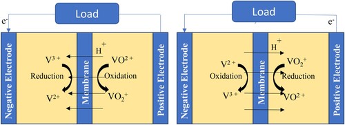
shows a schematic structure of a working RFB cell. Two tanks relate to liquid pumps for supplying the electrolytes that are stored in separate tanks on both the sides of the cell. The two sides are separated by a membrane to carry out the anode and cathode sides of the reactions separately into two half cells. As shown in , the structure of RFBs is considerably different than the conventional batteries, which are completely sealed and do not have any circulation system. The flow batteries also provide more design flexibility due to the use of transportable liquid electrolytes and variable storage capacity based on the size of the tanks used for storing the electrolytes. The power and energy capacity of flow batteries can be adjusted by adjusting the storage of liquid electrolyte, which also helps in adjusting the overall efficiency of the system. Both the power density and energy capacity are also independent in flow battery systems. The flow batteries have more stability than conventional batteries because of the external tanks. The installation and design of the auxiliary cooling systems in the flow batteries is comparatively easier because of the option of placing the external storage tanks in underground or building basement, thus it provides the freedom to choose the location for cell stack where the heat can be easily dissipated. can be used to assess the different types of existing energy storage systems, their features, and key characteristics (Citation22).
Figure 1. Schematic structure of RFB cell.
Based on the preceding discussion and properties listed in , flow batteries like VRFBs possess numerous advantages and are commonly used. Next, we present the primary components used in the design of RFBs.
2. Cell components
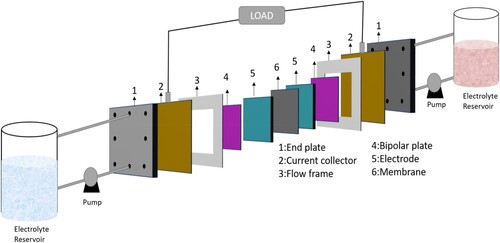
An electrochemical cell and two electrolyte container tanks are the main components of an RFB an electrochemical cell consists of two electrodes and one membrane that separate the electrolytes in each cell with the circulation of the electrolytes from the tanks. The redox active materials of cathode and anode are dissolved in the electrolyte and the electrolyte which passes through the cathode side is called catholyte, and electrolyte passing through the anode side is called anolyte. The electrochemical cell is divided by a membrane into two half cells to avoid the mixing of the electrolytes, while allowing the passage of H+ ions. Cathode is always the positive electrode and anode is the negative electrode. As shown in , the electrochemical cell construction, the bipolar plate plays important multifunctional roles. The end plate gives mechanical strength to the cell, while electrical isolation between the half-cell is ensured by the isolation plate. Graphite felt contains a large surface area and it acts as electrode. Flow frames in the cell distribute the electrolytes towards the cell chamber. Finally, the center of the cell is divided by a separator called membrane which divides the cell into two half-cells.
Figure 2. Schematics of RFB cell components.
Commercial RFB needs the entire cell assembly, pumps, fluid technology, sensors, battery unit, actuators, etc. The battery chemistry used in the RFB directs the design of cells and cell stacks. The current efficiency (also termed as columbic or faradic efficiency), voltage efficiency, and energy density are the frequently used parameters in the RFB system. The current efficiency is defined as the ratio of the total charge delivered by the battery to the charge stored up, whereas the ratio of the average discharged voltage to the average charged voltage is known as voltage efficiency. The ratio of energy (in watt hour) discharged to charged energy is called energy efficiency. The overall performance of a system is directly related to the energy efficiency, which is considered as the key parameter of the system for comparative analysis.
(1)
(1)
(2)
(2)
(3)
(3)
The conventional batteries are also assessed in a similar fashion with the electrolytes stored inside the cell component, whereas in an RFB the electrolytes have separate storage tanks outside the cell. The following section covers each component in RFB cells, their features, and recent advancements.
The primary RFB cell components are as follows:
Membrane
Bipolar plate
Electrode
Electrolytes.
2.1. Membranes
Over the last five decades, ion exchange membranes have received considerable interest in furthering the technological development of RFB from a laboratory scale to industrial scale targeting large techno-economic impact. Electrodes, soluble redox couples, and an ion-selective separator (ion exchange membranes (IEMs)) are the three major components of a battery (Citation23). The membranes are also named separators, as they separate or prevent the electrolyte solutions from mixing and thereby control the reaction between the half-cell. The selection of the separator is critical, as a cross-infection of electrolytes (both anolyte and catholyte) leads to a reduction in the efficiencies, and in case of asymmetric electrolytes it can cause a long-standing decay of capacity (Citation24). Membrane is a fundamental part in RFBs, however, in selected cases of RFBs membranes are not used. For example, flow batteries with two solid electrodes or batteries with a gas diffusion electrode are the rare types of RFBs (Citation25). The key properties that define a membrane's performance are ion selectivity and overall proton conductivity. A low ion conductivity directly affects the total coulombic efficiency, whereas an overall proton conductivity affects the performance of battery by decreasing the voltage (Citation26,Citation27). To reduce the impediment, the traditional method to develop ion-exchange membrane includes the polycondensation process. The cation and anion groups can be added to the ion exchange membrane to increase the ionic conductivity and selectivity, resulting in an improvement in the performance of membrane. shows the types of membranes and their performance in RFBs.
Table 2. Types of membranes and their performance in RFBs.
Based on their characteristics, membranes can be classified into three groups:
Ionic exchange membrane
Porous separators
Composite membrane.
2.1.1. Ionic exchange membrane
In 1890, Ostwald developed a semi-permeable ion exchange membrane for the first time and noted that the membrane can be made impermeable to electrolyte while maintaining transport of cation or anion (Citation54). Ion exchange membrane (IEM) can be in the form of sheet, ribbon, or tube-shaped membrane, which prevents the mixing of two fluids and allows the way of only ion exchange (Citation55). The membranes are like a three-dimensional network made of cross-linked linear polymer chain to provide structural robustness and avoid the formation of polyelectrolyte solution when they contact with water. IEMs are like resins, with fixed ion functional groups and oppositely charged counter ions that provide electrical neutrality to the whole exchanger.
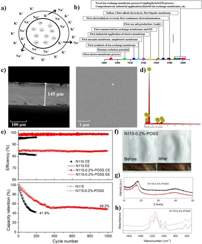
The ion exchange sites are the ionic functional groups, which can form an electrostatic bond with oppositely charged ions (Citation56). The ion exchange process occurs at a stage when the mobile counter ions in the solution are reinstated by another ion carrying the same charge. Ion exchange should be balanced in stoichiometry and is a reversible process. (a) depicts an example of an ion exchange process, which are frequently applied in various commercial applications (Citation57). A good IEM possesses high-conductivity/low-resistance, high ion exchange capacity (IEC), high permselectivity, high dimensional-stability/low-membrane swelling and water uptake, as well as high chemical, mechanical and thermal stability (Citation58). IEM technology has benefitted from extensive research expanded over a period that is more than a century. (b) shows a chronological timeline illustrating the development of IEMs and related proceedings (Citation54). These membranes separate the half cells and allow the ion passage only for the relevant chemical reactions. Mainly, the IEMs can be classified into two types as follows:
Cationic ion-exchange membrane
Anionic ion-exchange membrane.
Figure 3. (a) Schematic representation of an ion exchange process, (b) the timeline visualization of ion exchange membrane development and their related processes, (c) SEM and (d) EDX profile of N115-0.2%-POSS, (e) long-term run and capacity retention of VRFB connected with N115 and N115-0.2%-POSS at 80 mA cm–2, (f) real-time image, (g) XRD profile, (h) FTIR spectrum of N115-0.2%-POSS before and after stability run (Citation53,Citation54,Citation57).
2.1.1.1. Cationic ion-exchange membrane
Cationic ion-exchange membrane (CEM) was first developed by DuPont in 1970, which quickly became the most popular and widely used membrane in RFBs owing to the excellent activity and performance. CEMs contain fixed anion groups and exchangeable cations, with negatively charged functional groups in their structure. The examples for those functional groups are –SO3–, –COO−, –PO32−, –PO3H−, and –C6H4O− (Citation16,Citation20). The role of separator is to avoid mixing of electrolytes and electrode short-circuiting and maintaining charge neutrality in the system (Citation59). Due to high ion conductivity, the CEMs are the most preferred separator for vanadium oxide RFBs (VRFBs). As the CEMs provide a rapid transport of protons, they also make the passage of vanadium ions feasible through the membrane itself, which, in some cases results in cross-contamination of the electrolyte reducing the specific capacity of the battery. The positive charge carrying anion exchange membranes (AEMs) (Citation60) have been reported to reduce the cross-contamination, by the hypothesis of Donnan exclusion, of the positive ions. Because of low ionic conductivity, low membrane charge density and chemical stability, the AEMs do not block the vanadium ions (Citation61).
The fluorinated membrane and non-fluorinated membrane are the subgroup of cationic exchange membrane based on their base polymer. Perfluoro sulfonic acids (PFSAs) are a standard material for fluorinated exchange membrane. The fluorinated exchange membranes are chemically stable towards oxidants and reductants and possess reasonable stability in moderately concentrated alkaline and acidic medium. One example of these exchange membranes is NAFIONs, manufactured by DuPont, which are widely used in RFB because of their long-term chemical stability and excellent proton conductivity. Nafion membranes contribute to a significant portion of the overall cost of such systems, and the development of a compatible low-cost membrane can substantially reduce the final cost of the system. Nafion membranes are mainly composed of a polytetrafluoroethylene (PTFE) backbone with side chains containing ether groups and a sulfonic acid unit at the end. The number of fluoro propyl ether groups in the membrane structure impacts the chemical stability and swelling behavior of the membrane. In 1981, Gierke et al. developed the Nafion structure with a network of water clusters in spherical form that are connected through channels (1 nm in diameter) (Citation62). Solution casting (extracted from solution) or the extrusions of Fluor sulfonic acid precursor followed by the alkali hydrolysis are two different ways to obtain the PFSA membrane. The casting of membranes from a solution is generally preferred over the extrusion method, with the formation of inverse micelles as the conductive domain that leads to the ionic channels (Citation63). All of the tested membranes are in the group of sulfonated functional groups, for example, in poly (phenyl sulfone) (Citation64), poly(phthalazinone ether ketone) and tungstophosphoric acid composite (Citation65), poly(ether sulfone), sulfonated poly(ether-ether ketone) composite (Citation66), poly(ether ether ketone) composite, polypropylene and perfluoro sulfonic acid (Citation67), poly(arylene ether) (Citation68), poly(phenylene) (Citation69), poly(fluorenyl ether ketone sulfone) (Citation70) poly(ether-ether ketone), and poly(1, 4-phenylene ether-ether sulfone) (Citation71). These advanced membranes show superior performance than the Nafion membranes with high ion selectivity, low vanadium ion permeability, high coulombic efficiency, and good chemical stability.
According to a study, Hongli et al. incorporated chemical grafting method to prepare amino propyl isobutyl polyhedral oligosilsesquioxane (NH2-POSS) surface-modified Nafion membrane, which looked like a cage macromer consisting of an inorganic Si8O12 core surrounded by one active aminopropyl group and seven inert isobutyl groups (Citation53). For further modification with NH2-POSS, the sulfonic acid groups on the surface of Nafion can be activated by 1,1-carbonyldiimidazole. NH2-POSS with different concentration was successfully grafted on the surface of Nafion 115 and the formation was confirmed with scanning electron microscopy (c and d), Fourier transform infrared spectroscopy (FT-IR), and x-ray photoelectron spectroscopy (XPS). The organic–inorganic hybrid membranes displayed enhanced ion selectivity and excellent dimensional stability with lower water uptake and swelling ratio better than Nafion 115 membrane. In the case of VRFB also, the surface modified Nafion membrane achieved improved performance than Nafion 115. The VRFB with modified Nafion shows average coulombic efficiency (CE) of 98.7% and energy efficiency (EE) of 84.5% at a current density of 80 mA cm–2, whereas in Nafion 115 the coulombic efficiency (CE) was 95.7% and energy efficiency (EE) was 81.7% respectively. The cell holding high-capacity retention after 1000 charge–discharge cycles for modified Nafion membrane RFB was 49.2%, while the same for Nafion 115 was 41.7% as shown in (e). The real micrograph of N115-0.2%-POSS after long-term stability run is shown in (f) (Citation53). The FTIR spectrum retained the band position after cycling, as in (g), shows strong evidence of acid and high oxidation resistance of POSS, while the XRD image in (h) shows a slight deviation from 18° to 17.5° could be due to the leakage of POSS in the embedded Nafion nanocluster during the 1000 cycle stability operation. These results indicate the use of POSS surface modified Nafion membrane as a promising candidate for RFBs.
Research on the development of high performing membrane is still underway, with more researchers using sulfonated aromatic polymer membranes with sulfonated functional groups. According to Jinchao et al., sulfonated polymer membrane shows low cost, low vanadium permeability, and good ion selectivity. The membrane for the application in VRFBs is synthesized by X-shaped tetraamine monomer 4,4’,4’’,4’’’-(1H,3’H-[5,5’-bibenzo[d]imidazole]) tetra aniline with imidazole groups. A series of novel sulfonated polyimide membranes with covalent self-cross blinking and branching structures (sc-bSPI-x) are designed. Highest ion selectivity (2.78 × 10⁵ S min cm−3) was shown in the sc-bSPI-x membranes where the sc-bSPI-14 membrane had 14% theoretical cross-linking degree, which is 6.5 times greater than commercial Nafion 212 membrane (0.43 × 10⁵ S min cm−3). The performance of sc-bSPI-14 membrane at 80–200 mA cm−2 including coulombic efficiency, energy efficiency, self-discharge has a superiority over the Nafion membrane. The self-discharge time for sc-bSPI is 41 h, the coulombic efficiency is 97.6–99.2%, and the energy efficiency is 82.9–63.2%. In the case of Nafion 212, the self-discharge time is 11 h, the coulombic efficiency is 86.5–94.5%, and the energy efficiency is 78.4–61.4%. Also, the cyclic charge–discharge for 1000 times at 140 Ma cm−2 was tested, in which sc-Bspi-14 gives an outstanding performance than Nafion (Citation30). However, the deposition of vanadium species on the surface and internally within the membrane is the primary limitation of PFSA membrane. The limitation is due to the fouling process. Fouling occurs when vanadium species deposit on the surface of the membrane and affect the movement of ions resulting in a low mobility if cations through the membrane and a subsequent degradation in charge–discharge performance of the system (Citation72). Soaking the membrane in sulfuric acid is one of the methods reported to reduce the condition of membrane fouling (Citation27). The post modification of polyphenylene sulfone (Citation64) or polyimides by sulfonation (Citation73,Citation74) are the methods of obtaining the nonfluorinated membrane, which do not exhibit the desired chemical stability in vanadium electrolyte solution (Citation75,Citation76) and tend to form cracks resulting in collapse of RFBs.
2.1.1.2. Anionic ion-exchange membrane
The anion exchange membrane (AEM) offers a superior performance in terms of selectivity than cation exchange membranes that can result in high current efficiency in RFB none the less at the cost of a reduced conductivity. This type of membrane is commonly used in aqueous–organic system (Citation77,Citation78). AEM contains fixed cationic group and exchangeable anions embedded in suitable polymers, where metal cation-based groups are also found to be suitable, in addition to the common functional groups (Citation79). A positively charged zirconium-based metal organic framework is one example, which has shown improvement in hydroxide conductivity (Citation80). The extraction of hydrogen from water under alkaline conditions can be achieved with poly fluorenyl-co-aryl piperidinium (PFAP)-based anion exchange materials (electrolyte membrane and electrode binder) that possess high ion conductivity and durability. These membranes enclose positively charged groups in their structure that include –NR3+, –PR3+, –NH3+, –NRH2+, –NR2H+, –SR2+ (Citation81).
In CEM, the cation exchange groups are strongly attached to their structure, while in the anion exchange membrane, the bonding of the anion exchange groups is not very strong (Citation82). Chen et al. showed that both protons and sulfate anions can be effectively transported (Citation83). Low ion permeability, reduced area resistance, stable open circuit voltage for a long period of time (Citation84), greater energy efficiency, vanadium selectivity (Citation85), diminished water transport (Citation86); improved efficiency of energy, voltage, and total system (Citation87) are not able characteristics reported for AEM-based flow batteries. These results are a positive sign to the future development in anion exchange membranes in RFBs that can compete with the existing Nafion membrane.
Sukhwan et al. studied cardo-poly (ether ketone)-based AEMs as separator in vanadium–cerium flow battery. The energy efficiency (EE) of this V–Ce battery was observed to be 67–84% at a current density between 20 and 80 mA cm−2 (Citation88). The battery with Nafion 212 had an energy efficiency range from 50% to 84%. Due to the cation intermixing, the Nafion membrane battery had significant capacity and efficiency losses, whereas the AEM did not show capacity and efficiency loss in over 20 charge/discharged cycle (Citation88). Also, no significant change was seen in the ionic conductivity, ultimate tensile strength, and Young's modulus in AEMs after 50 charge/discharge cycles (Citation88). Lallo et al. compared five types of membranes, three AEMs and two CEMs. AF1-HNN5-50-X, AF1-HNN8-50-X, and AF1-ENN8-50-X were the three aemionTM AEM and Nafion 211, Nafion 212 were the tested CEMs (Citation89). They concluded that the three aemionTM AEMs showed outstanding performance than the CEMs. The VRFB using AEMs displayed high efficiency and low total resistance compared to Nafion 211 and 212. On the other hand, when using AF1-ENN8-50-X membrane, a relatively high-capacity loss of 28.7% was observed. Overall the studies based on AemionTM AEM showed a superior performance than that of CEMs (Citation89).
Singh et al. synthesized a modified AEM by cross-linked aliphatic polymer with side chain grafted imidazole using alkali chain spacer (Citation90). The synthesized anion exchange membrane had great vanadium ion impervious nature and ionic conductivity. An ion exchange capacity of 1.21 meq g–1 and conductivity of 8.1 × 10 S cm–1 were observed by the cross-linked methyl methacrylate-co-vinyl imidazole copolymer (CMVI) with C3 spacer (CMVI-C3). Due to blocking property of CMVI AEMs for VO2+, the VO2+ permeability (1.96 × 10) of CMVI-C3 AEM was extremely low compared to Nafion 117 (16.34 × 10). Compared to Nafion 117 membrane, the CMVI-C3 AEMs had more coulombic (98.8%), energy (78.2%) and voltage (80.5%) efficiency at 120.0 mA cm−2. Up to 200 charge/discharge cycle, the CMVI-C3 AEM showed a superior performance than Nafion (Citation29). Time-dependent open circuit voltage (OCV) curves provide information regarding self-discharge rate of VRFB operation. Different membranes (CMVI-C3, CMVI-C10, and Nafion 117) were evaluated for self-discharge at half charge condition till lower cut off (0.8 V), where the CMVI-C3 membrane was found to have a good potential for RFB applications. In addition to the CEMs and AEMs, proton exchange membranes (PEMs), bipolar membranes, amphoteric IEMs (also known as charged mosaic membranes), monovalent selective IEMs, and mixed matrix membranes (MMMs) are other specific types of membrane. PEMs are used to collect proton in fuel cells and falls under the category of common types of cation ion-exchange membrane (Citation49). The proton exchange membranes (PEMs) generally have high proton conductivity, low vanadium permeability, and good chemical stability (Citation91). Bipolar membranes, as the name indicates, contain both anionic and cationic groups. This membrane is made up of two layers, cationic exchange layer (CEL) and anionic exchange layer (AEL), which behave like CEM and AEM respectively (Citation92). The interface of the two layers serves as water dissociation zone to produce hydrogen ions and hydroxide ions using external power supply (Citation93), displaying potential use for electro dialysis (Citation94). Amphoteric ion-exchange membrane is like the bipolar membrane consisting of both cationic and anionic groups, are made by the radiation-graft copolymerization of prefabricated films or powdered PVDF (Citation95,Citation96) or ETFE (Citation97) with the help of gamma rays. The monovalent selective ion-exchange membrane is a type of membrane which separates monovalent ion from the solution (Citation98,Citation99). Monovalent selective cation ion-exchange membrane (Citation100,Citation101) and monovalent selective anion ion-exchange membrane (Citation102,Citation103) are two types of monovalent ion-exchange membranes which have been used in applications such as energy conversion through reverse electrodialysis (Citation102), reverse osmosis via electro dialysis (Citation104), and removal of arsenic and nitrate ions from ground water (Citation105).
2.1.2. Porous separators
The porous separators are mainly used in flexible polymer systems. Chieng et al. (Citation106) incorporated cost-effective Daramic® microporous separators in VRFBs to exploit the chemical stability of Daramic in vanadium electrolytes. The initial coulombic efficiency of the membrane, 77%, was increased to 90% after treating the membrane with polyelectrolyte/ion exchange resin. Mohammadi and Skyllas-Kazacos (Citation107,Citation108) studied the chemical stability of Daramic®, modified Daramic®, and several commercial ion exchange membranes in the vanadium redox battery (VRB). Due to increasing composite in daramic membrane, the stability of membrane decreased over a period. Porous solids are categorized because of pore size (PS) as nanoporous (PS < 1 nm), micro porous (1 < PS < 2 nm), mesoporous (2 nm < PS < 50 nm) and microporous materials (PS > 50 nm). Similarly, the filtration membrane classifications are taken to be nanofiltration membranes (PS < 5 nm), ultra-filtration membrane (5 < PS < 100 nm), and microfiltration membranes (100 nm < PS < 10 μm) based on the PS used in the manufacturing of the membrane. These types of separators are suitably treated to be used for RFBs applications otherwise the redox active ions will pass through the membrane and the efficiency will be decreased.
In a retroactive modification, the pores of daramic separators are filled with crosslinked polymers to provide a suitable variation (Citation109). After pore filling, the passage of large ions can be prevented without limiting the ion conductivity of protons. An ionomer solution, a solution of ion exchange, can be used to fill the pores of microfiltration membranes for achieving high-level ion selectivity (Citation110,Citation111). The phase inversion method is another common technique for producing microfiltration or ultra-filtration membranes. Controlled transformation of polymer from liquid state to solid state is known as the phase inversion method that was developed by Loeb and Sourirajan (Citation112). For increasing the selectivity and wetting of pores, inorganic fillers such as methyl ortho silicates can be used for covering and filling the pores (Citation113). These membrane examples are based on polycrylonitrile (PAN) (Citation114), polyether sulfone mixed with sulfonated polyether ether ketone (PES/SPEEK) (Citation115), and polyvinylidene fluoride (PVDF) (Citation116).
Nanofiltration membrane is one of the most promising membranes which is utilized under a pressure difference of 5–20 bar between the two sides to force guide the permeation of ions through the small pores of membrane (Citation117). The functioning mechanism of these membranes is different than ion exchange membrane and it works on the principle of adjusting selectivity between H+ protons and vanadium ions by neglecting the pore size (Citation114). The charge density and Stokes rays of vanadium ions are much greater than H+ ion due to which the nanofiltration membrane can efficiently separate the vanadium ions from the protons. Also the radius of vanadium species and H+ ions is considerably different to help the membrane work efficiently (Citation114). The pores of the nanofiltration membrane, which allow only H+ ions to pass through due to their smaller size, contribute to their exceptional performance. The small pore size of nanofiltration membrane is one of most critical parameters to prevent the passage of larger ions. In addition, it is seen that when the pore size increases the efficiency of RFB consequently decreases (Citation118). Zhang et al. (Citation114) reported the testing of highly selective V/H nanofiltration membrane, composed of polyacrylonitrile, which provided a coulombic efficiency of up to 95% and an energy efficiency of 77%. Later, Zhang et al. (Citation113) introduced some silica to the membrane to increase the V/H ion selectivity, which resulted in improving the battery coulombic efficiency up to 98% and the energy efficiency up to 79%. According to another study by Xi et al. (Citation119), the modification of poly (ether sulfone) nanofiltration membranes by silica significantly increased the performance of the membrane. Compared to the efficiency of the original nanoporous separator, the coulombic efficiency increased by more than 10% and the energy efficiency increased by 7% in the presence of silica. As reported by Wei et al., silica was added into the polytetrafluoroethylene matrix for the modification of the membrane (Citation118). After the modification, the VRFB displayed a great improvement in electrochemical performance, with high energy efficiency of 80% and increased coulombic efficiency of 93%. The cost of the silica-based material is also comparatively low while they show great performance when included in RFBs.
2.1.3. Composite membrane
Composite membranes are made up of two or more layers of different materials. During the solution casting in the sol–gel process, the composite membranes are generated by incorporating organic material into a polymer matrix. Some examples for composite membranes include polytungstate in sulfonated polyphenylene sulfide (PPS) (Citation120), silicates in nafion or partially fluorinated SPEEK (Citation121), and zirconium phosphate in partially fluorinated SPEEK (Citation122). A composite membrane is structured with a thin layer of selective material deposited upon a porous sub-layer to as a support. The overall performance of a composite membrane is based on the influence of these sublayer materials and the way the layers are fabricated and inserted. Dip coating, spin coating, plasma polymerization, spray coating, interfacial polymerization, in-situ polymerization, and grafting are different techniques reported to be used to apply a thin top layer onto the support. A variety of techniques are available for the preparation of membranes; in addition, many polymers are also available to be used in composite membranes.
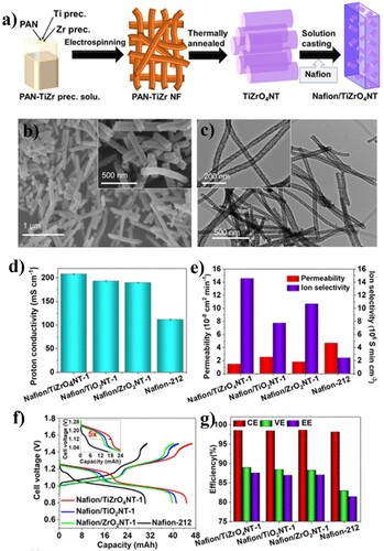
A single layer composite membrane consists of only two layers, a thin layer, and a support layer. The support layer provides mechanical strength and the thin layer acts as a separator. Overall, the cost of production of these membranes is comparatively low, providing a competitive edge against other membrane types. A multi-layered composite membrane consists of several layers of different materials and a porous support. Application wise gas separation, nanofiltration, reverse osmosis, and per evaporation utilize thin-top layer composite membranes. A selective layer can be applied in such methods like lamination, solution coating, interfacial polymerization, or plasma polymerization methods. The choice of the material from which the separating layer and the porous support layer are developed, and their manufacturing techniques define the functionality of composite membranes and provide numerous benefits over the asymmetric membranes. Abdul Aziz et al. prepared a composite of Nafion membrane modified with single-phase TiZrO4 nanotubes (Nafion/TiZrO4NTs) for the cobalt–tungsten all-heteropoly acid RFB (H6[CoW12O40] RFB) as shown in (a–c) (Citation123). A proton conductivity of 207.9 mS cm−1 (d) and anionic conductivity six times higher (e) were generated by the NAFION/TiZrO4NT composite membrane compared to industrial NAFION-212 membrane with proton and ion conductivity of 111.4 mS cm–1 and 2.39 × 10⁶ S min cm–3 respectively. The discharge capacity (44.8 mA h) was significantly improved with the use of a Nafion/TiZrO4NT composite membrane. In addition, high voltage efficiency (88.9%) and an energy efficiency (87.5%) show excellent enhancement compared to NAFION-212 membrane which had a discharge capacity of 30.2 mAh, low energy efficiency of 81.4% and 82.9% of voltage efficiency is detailed in (g). The comparison in (g) always shows the superiority of Nafion/TiZrO4NT composite membrane over the Nafion 212. Also, the improvements in the open circuit voltage of 190 mV, battery cycling efficiency at different current densities are noteworthy achievements of the Nafion/TiZrO4NT composite membrane. When utilized in the cobalt–tungsten all-heteropoly acid RFB, the membrane showed an outstanding performance, suggesting that it can be used to replace Nafion 212 membrane for improved performance.
Figure 4. (a) Illustration on the synthesis process of TiZrO4NTs and Nafion/TiZrO4NTs, (b) FE-SEM, and (c) FE-TEM image of TiZrO4NTs, (d) proton conductivity, (e) permeability and ion selectivity values of the different composite membranes, (f) charge–discharge voltage profile, (g) performance efficiencies of various Nafion/NT membranes at 5 mA cm−2 (Citation123).
Kwan Ju Lee et al. studied a composite membrane with Graphene oxide (GO) and Nafion (Citation124). The fabrication of GO/Nafion composite membranes encompassed varying GO compositions from 0.001 to 1 wt%. As per the analysis, because of a lower value of vanadium permeability, water uptake and proton conductivity than the Nafion 117 membrane, the composite membrane had a lower value of the inter-planar space dimension. As the GO composition in the composite membrane increased, there was a reduction in both proton conductivity and vanadium permeability. The optimal range for GO composition in the composite membranes, specifically for the ion-exchange membrane in the vanadium redox flow battery (VRB) system, was identified to be between 0.01 and 0.1 wt%. Notably, the application of a 0.01 wt% GO composite membrane resulted in the highest energy efficiency (EE) value for the VRB single cell, reaching 82.5%. This observation suggests that the GO/Nafion composite membrane holds significant promise as a compelling candidate for the VRB membrane electrolyte.
2.2. Bipolar plates
Bipolar plates have multifunctional roles and are one of the most important components of RFBs. The bipolar plates connect each cell electrically while separating them chemically and provide mechanical stability to each cell and cell stacks. In addition, the electrolyte distribution into the cell is governed by the bipolar plates used in the system. To fulfill their critical role, following features are required in the design and development of bipolar plates:
Good mechanical stability
High electrical conductivity
Resistance against acidic medium
High over potential for hydrogen evolution
Lower contact resistance especially with electrode.
Metallic bipolar plate
Graphitic bipolar plate
Carbon polymer composite bipolar plate
Carbon–carbon composite bipolar plate.
provides a quick comparison of advantages and disadvantages of different bipolar plates.
Table 3. Comparison of advantages and disadvantages of different bipolar plates.
2.2.1. Metallic bipolar plate
The metallic bipolar plates have advantages of outstanding thermal and electrical conductivity, easy machinability, and good mechanical stability. The main disadvantage of this type of bipolar plates is the tendency towards the surface corrosion and the large probability of occurrence of unwanted reaction pathway such as hydrogen evolution reaction (HER) and oxygen evolution reaction (OER) (Citation127,Citation128). In the case of VRFBB, the vanadium electrolyte gets contaminated by the metal ion dissolution due to the rapid surface corrosion of metallic bipolar plate. It also affects the RFB performance due to the parasitic reaction and gas evolution (Citation129). Owing to these challenges, many researchers are trying to develop bipolar plate with anti-corrosion strategies. Liu et al. developed metallic bipolar plate of titanium (Ti) and coated with carbon film (TCPF) through a process of electrode position in a LiCl–KCl–K2CO3 molten salt for the RFB. Due to the Ti–O–C gradient, amorphous and crystallized phases in the carbon film show good adhesion with Ti. Compared to the bare Ti plate, TPCF bipolar plate exhibited a more positive value of Ecorr by 969 mV for polarization characteristics in 2M H2SO4. So, they suggested that carbon film protects the Ti from critical acid corrosion, while observing no oxidation on the carbon film during the VRFB operation. In addition, a charging potential of 1.2 V still maintains the surface morphology of the TPCF plate. The carbon film starts to show failure when the charging potential reaches 1.5 V. The TPCF bipolar plate can only be used in RFB where the charging potential difference is strictly controlled to a value below 1.2 V, which makes the working potential range a limiting factor.
Burak Calgar et al. developed bipolar plates using a mixture of stainless steel 1.4301 and titanium alloy 3.7165 and coated with diamond like (DLC) coating films doped with vanadium, tungsten, titanium, and chromium elements (Citation130). They reported a significant shifting in hydrogen evolution reaction (HER) potential and improved corrosion resistance in 2M H2SO4. Haan et al. developed a metallic bipolar plate of IrOx layer coated nanotubular TiO2deposited on Ti substrate (IrOx-coated TiO2 NTs). The IrOx-coated TiO2 NTs bipolar plates showed better performance than conventional graphite bipolar plate of VRFB with 0.3M VOSO4 + 0.6 M H2SO4 solution. After 100 charge–discharge cycles at 40 mAcm−2, no degradation was noted on the IrOx layer. They reported an improved voltage and energy efficiency, low charge–discharge over potential and improved specific capacity for the IrOx-coated TiO2 NTs bipolar plates.
2.2.2. Graphitic bipolar plate
Graphitic bipolar plates are considered an excellent choice for RFB owing to their high electrical conductivity and chemical stability. But the relatively high cost limits the scale-up interest and requires further research and development to overcome this barrier. The kW scale power of the VRFB is mostly developed through the utilization of graphite bipolar plate (Citation131). The positive electrode surface corrosion and swelling, low mechanical strength, interfacial contact resistance, difficult machinability and high manufacturing cost also constitute to the limitation of the commercial prospect of graphite bipolar plate (Citation132,Citation133). Graphite is brittle in nature and requires being fabricated thicker (4–6 mm) to maintain mechanical integrity, which consequently increases the volume, weight, and cost of the RFB stack. In graphite bipolar plates, the electrolyte permeation at the positive side of the electrode and the surface swelling can be reduced by increasing the interfacial contact resistance between the bipolar plate and the electrode, which also reduces the electrical conductivity (Citation134). These challenges provide opportunities for new researchers to consider these factors while developing graphite polar plate with acceptable behavior in RFB.
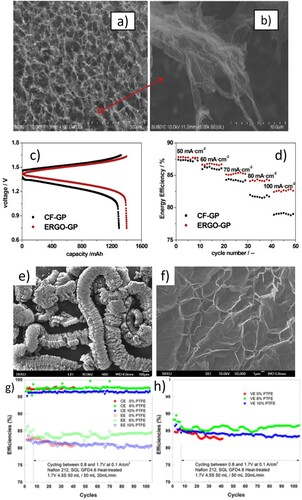
Jing et al. assembled an integrated electrode-graphite bipolar plate, ERGO-GP, by a novel 3D method consisting of electrochemically reduced graphite oxide (ERGO) porous gelatum material electro deposited on flexible graphite as shown in (a and b) (Citation135). The ERGO itself can be used as an electrode for the RFBs. Comparatively the ERGO-GP showed superior electrochemical performance than conventional carbon felt-graphite plate (CF-GP). Also, it has excellent charge transfer resistance and improved reversibility when compared to CF-GP assembly. The energy efficiency in (d) of the VRFB coupled with ERGO-GP is 6.2% higher than that of CF-GP at a charge–discharge current density of 100 mA cm−2, which make it a promising candidate for the future applications in RFB with graphite bipolar plate. Qian et al. prepared a novel electrode-bipolar plate for reducing the interfacial contact resistance between bipolar plate and porous electrode in the RFB, which consists of graphite felt (electrode), an adhesive conducting layer (ACL), and a flexible graphite felt (BP) (Citation134). Compared to conventional graphite bipolar plate the flexible graphite bipolar plate displayed a high electrical conductivity, reduced weight, and low cost. For the fabrication of the assembly, they first prepared the carbon black, and then used the ACL composed of resin and graphite powder on the flexible graphite bipolar plate. By hot pressing at a temperature of 150°C the porous graphite felt was heated to provide mechanically strong and uniform assembly. The resulting graphite bipolar plate showed an outstanding performance with 10% of lower cost, 40% decreased area resistivity, 11% improved energy efficiency, 150% increased electrical conductivity and avoiding the relative permeation of electrolytes when compared to conventional electrode-bipolar assembly. ACL helps in increasing the number of contact points between graphite felt and bipolar plate, which magnified the electrical conductivity and decreased the charge transfer resistance, and over potential in the RFB system. Recently Kim et al. developed a flexible graphite ultra-thin bipolar plate (0.76 mm) made up by the continuous rolling process of expanded graphite matrix and adding an additive, polytetrafluoroethylene (PTFE), as shown in (e–f) (Citation133). The swelling nature of bipolar plate in the corrosive vanadium electrolytes was reduced by the addition of PTFE. The expanded graphite with no PTFE had a high electrical conductivity of 41.7 mΩ cm, however, suffered from extremely high swelling in the electrolyte solution containing 1.7 M VO2+ + 4.5 M H2SO4. These factors reduced the cell efficiency of the RFB by 2.3% after 35 charge–discharge cycle as shown in (g–h). After adding 6% to 10% of PTFE in the expanded graphite bipolar plate, swelling suppressed, and the cell efficiency of RFB increased. Although it exhibited less area resistance and ohm loss, reduced permeability, better corrosion resistance, and excellent electrochemical performance of RFB are the desired benefits of ultra-thin graphite bipolar plate.
Figure 5. (a) SEM images of ERGO, (b) magnified SEM image, (c) charge–discharge profile of ERGOs at 100 cm−2, (d) energy efficiencies at different current densities, (e) SEM image of expanded graphite, (f) magnified, (g–h) cyclic performance of different concentration of PTFE (Citation133,Citation135).
2.2.3. Carbon polymer composite bipolar plate
As per the above-mentioned properties of both metallic and graphite bipolar plates, the metallic bipolar plates show good mechanical strength and ease of machinability; however, their chemical stability in corrosive electrolytes is poor, whereas the graphite bipolar plates have high corrosion resistance but poor mechanical strength and a relatively high cost of manufacturing. Due to these compromising factors, researchers are looking for high performing alternative bipolar plates with appropriate balance in cost and functionality. Carbon polymer and carbon–carbon composite bipolar plates have recently gained more attention as they provide more flexibility for design while lowering the manufacturing cost compared to pure graphitic plates (Citation136,Citation137). Polymer resin matrix such as thermoplastic and thermosetting can be mixed with carbonaceous conducting fillers by way of several processes like injection molding, compression molding, and casting to prepare carbon–polymer composites (Citation138,Citation139). With the help of injection molding and compression molding techniques the carbon–polymer composite bipolar plate with flow channels can be easily made in a short period with low cost. Most of the polymers are electrically insulators and can be used as continuous matrix. Graphite powder (Citation140), carbon fiber (Citation141), carbon nanotubes (Citation142), exfoliated graphite (Citation143), carbon black (Citation144), and graphene (Citation145) are materials which enhance the electrical conductivity of the composite. The carbon polymer composite bipolar plates have shown high electrical conductivity and good mechanical stability, which makes them a suitable choice for RFBs.
As reported by Choe et al. the performance of bipolar plates greatly impacts the efficiency of the VRFB (Citation146). The surface area of the electrode and the flow of electrolyte are based on the shape of the bipolar plate. To increase the efficiency of electrolyte flow and decrease area-specific resistance (ASR) in the RFB, they prepared a corrugated carbon/epoxy composite bipolar plate (CCBP) (Citation146). The apt shape of the bipolar plate significantly decreases the ohmic and pumping losses in RFBs. The purpose of CCBP was to provide and adjust the electrode areas between the high and low fiber volume fraction. The electrical resistance is low in high fiber volume fraction area, and the electron path is also reduced. In the case of low fiber fraction area pumping losses are significantly decreased providing a smooth pathway for electrolytes to flow. As the changing electrical resistance and the permeability of fabric materials are represented in terms of fiber volume fraction, the non-uniform compression of the carbon fiber electrode in CCBP may exhibit a synergistic effect for decreasing overall losses (Citation147), making CCBP is a good product with numerous benefits when utilized in RFB. According to a study of Lee et al., the promising carbon/epoxy composite bipolar plate showed high mechanical strength and improved performance to overcome the demerits of conventional graphite bipolar plate in the RFBs (Citation148). They performed an expanded graphite coating or additional surface treatments to the carbon/epoxy composite bipolar plate for decreasing the interfacial contact resistance. The carbon/epoxy composite bipolar plate showed a multifunctional structure; however, under the RFBs operating conditions the expanded graphite coating had low durability. As surface treatments are costly to implement, they uniformly removed the resin-rich layer and exposed carbon fibers on the surface of the carbon/epoxy composite by excess resin-absorbing method developed with polyester fabric (Citation148). As a result of the treatment, the exposed carbon fibers decrease the interfacial contact resistance and the generation of unique ditch pattern helped in fixing the carbon felt electrode in place. The composite bipolar plate showed high durability against acidic environment, high gas permeability, and mechanical strength.
Liu et al. studied the performance of RFBs consisting of carbon-based bipolar plates (Citation149). The conventional preparation methods of carbon composite plates did not result in acceptable mechanical stability and electrical conductivity, and they proposed an alternative four-step method to manufacture carbon bipolar plates with carbon plastic materials. First, the carbon felt is coated with polyvinylidene fluoride (PVDF) solution, followed by solvent evaporation, hot-pressing and surface modifications to fabricate the carbon polymer composite bipolar plate. High corrosion resistance, excellent mechanical strength, and high conductivity were achieved by the resulting bipolar plates. In the surface modification step, the PVDF-rich layer is removed from the surface and coated with carbon nanotubes (CNTs). The resulting composite showed good flexibility and battery charge–discharge cycle measurements. The RFB with carbon polymer composite bipolar plate also exhibited good stability, providing a suitable alternative to be used in RFB with increased efficiency and long-term stability. Ruban et al. used carbonized elastomeric based composite material to fabricate their bipolar plate (Citation150). The resistance of the RFB with the carbonized elastomeric was found to be 0.20 Ω cm–2, had elusive permeability, and suitable mechanical properties. The current densities in batteries with carbonized elastomer were found in the range of 50–150 mA cm–2, suitable for industrial RFB. Carbonized elastomeric with its superior performance can be considered a suitable option in RFBs.
2.2.4. Carbon–carbon composite bipolar plate
Carbon–carbon composite bipolar plate has similar layer patterns as seen in carbon–polymer bipolar plate. Instead of using polymer-based additives as in case of carbon–polymer, carbon group-based additive is used to develop the bipolar plates. The mechanical strength and the chemical stability of the carbon–carbon composite bipolar plates are found to be far better than the graphite and metallic bipolar plate. The production cost of these plates is also less compared to others. According to Caglar et al., the carbon–carbon bipolar plate, which is a composite form of synthetic graphite, has conductive filler made of carbon nanotubes (CNT) filled polyphenylene sulfide (PPS) (Citation151). The structure is achieved by using a Titanate coupling agent (KR-TTS) for improving the flow behavior of composite and the dispersion of the fillers. The CNTs and the additives of the bipolar plate display an outstanding performance when used in RFB. After adding a 2.5 wt.% CNT and 3 wt.% KR-TTS in 2.5 wt.% of total conductive filler concentration; the resulting composite showed exceptional performance compared to the sample without CNTs and additives. The electrical conductivity of through-plane increased from 1.42 to 20 S cm−l, whereas electrical conductivities of in-plane increased from 6.4 to 57.3 S cm−l. By the addition of 1.25 wt.% of CNTs, 15% flexural strength was increased. However, the threshold of this bipolar plate in the RFB has no standard for corrosion. Also, thus produced bipolar plates can be operated only between certain potentials without destructive surface reaction like oxygen or hydrogen evolution. Improvement in electrical conductivity of the composite bipolar plate is very important for improving the efficiency of the RFBs. Jiang et al. suggested the removal of resin-rich layer on the surface of the composite bipolar plate to improve electrical conductivity (Citation152). After surface treatment of graphite/resin composite bipolar plate with cactus-like carbon nanofibers, the performance, conductivity (198.7 S cm−1), and durability of the bipolar plate considerably increased. The area specific resistance decreased to 25.4 mΩ cm2 resulting in a high efficiency of 86.28% at 100 mA cm−2, along with an outstanding durability in charge–discharge cycling test. The benefits of modified carbon–carbon composite bipolar plate in terms of high efficiency and stable performance make them a promising candidate for RFB.
2.3. Electrodes
Electrodes are the main cell components where redox reactions take place and determine the capacity and the long-term stability in RFB. The redox couple reaction associated with the dissolved active agents in catholyte, and anolyte are facilitated on the surface of electrode, however, the electrodes (cathode and anode) are not expected to react. High specific surface area, high electrical conductivity, high electrochemical stability, and good mechanical stability at low cost are the looked-for properties of an ideal electrode. The surface area of the electrode plays a critical role on account of providing surface for reaction to take place, which can be modified by several treatments. Chemical doping (Citation153), addition of nanomaterials (Citation154), and chemical etching (Citation155) are frequently reported procedures to influence the redox reaction sensitive to the chemical state of the electrode surface. Thermal, chemical, electrochemical oxidations of the electrode surface are commonly reported, even though not desired. Essentially carbon-based materials such as carbon felt, carbon paper, and graphite felts are used as diffusion electrodes in RFB (Citation156). Carbon nanotubes (CNTs), carbon fiber, carbon paper, thermal hydroxylated and acid treated graphite and carbon–polymer composite materials, carbon cloth, iridium-modified (Ir-modified) carbon felt and graphene oxide (GNO) nanoplatelets are some of the emerging materials for electrodes being investigated for RFB (Citation157); none the less, carbon felt and graphite felt are the most common owing to low cost, high surface area, good conductivity, and good stability (chemical, electrochemical, and mechanical stability). Pure carbon and graphite, due to high brittleness, are increasingly being replaced by other relatively flexible materials. The utilization of brittle materials makes the scale-up of stacks very difficult, opening ways for composites of polymer binders like carbon–polymer composite (Citation158), conductive particles like polymer-impregnated graphite (Citation159) that seem to offer advantages in terms of less weight, low cost, and good mechanical properties.
Additionally, gold, platinum, lead, iridium oxide dimensionally stable electrodes (DSAs) and platinized titanium are some recent electrode materials being investigated for RFB, nonetheless only mixed results are reported so far (Citation160). Titanium electrodes, when used as a positive electrode in acidic systems, they become passivated in the potential range where the V (IV)/V (V) redox couple reaction occurs, whereas this problem is not exhibited on platinized titanium (Citation161). Similarly, lead electrodes also show this phenomenon (Citation160). A conducting polymer, such as polyaniline, when coated with carbon can be a better option as a positive electrode in RFB due to chemical resistivity of carbon (Citation160). The non-stability of the metal electrodes in electrolyte solution has been identified as a central challenge in metal electrode. The evolution of hydrogen and oxygen in aqueous electrolytes can be greatly prevented by using non-metal electrodes that can result in improving cell efficiency as the water splitting reaction (HER and OER) directly contributes to the efficiency loss and charge imbalance in RFBs.
Porosity in electrodes help in adjusting the surface area for redox reaction to take place, thereby regulating the overall charge transfer reaction. A porous electrode is a composite form of solids containing interconnected void spaces that considerably alter the electrochemical behavior and flow pattern within the vicinity of the electrodes as compared to that of planar electrodes. The porous electrodes can assist in regulating the charge transfer, improving mass transport and ohmic. Suitable electrode materials with high porosity have the potential for outstanding redox performance resulting in good economic benefits. Kim et al. studied the use of graphite-based electrodes fabricated using natural graphite (NG) powder and synthetic graphite (MCMB 1028) using a substrate resulting in dimensionally stable anode (DSA) (Citation162). The study of electrochemical properties in vanadium-based electrolytes helped to determine how to improve energy efficiency and durability of RFBs. They used a voltage range of −0.7 V to 1.6 V to perform the cyclic voltammetry (CV) experiments. Fast redox reaction and good reversibility in concentrated acidic electrolyte were showed by the graphite-based electrode. The electrochemical activity of the natural graphite (NH) for the redox reaction of V4+/V5+ was further increased by using the substrate, perhaps due to the functional groups of the conductive material acting as catalysts. The overall impact was in terms of high energy density, high power density, and improved efficiency of the battery system. The more types and features of electrode can be described in Section 3 in types of batteries which is in this review paper.
2.4. Electrolytes
Electrolytes are the active components in RFBSs where energy is stored in the form of varying oxidation states. The choice of electrolyte determines the potential window, safety, and the current capability in RFBs; and significantly impacts the properties of the cell, performance of RFBs, and the capital cost of the battery. From a practical application point of view, the energy density and operating temperature range are directly influenced by the chosen electrolyte composition, and a slight modification of the electrolytes can significantly affect the output in the performance of RFBs. Electrolytes are categorized into two parts: catholyte and anolyte, the electrolyte connected to cathode is termed as catholyte and the one connected to anode is anolyte, which contain the cathodic and anodic compounds of different elements. In addition to using pure elements in different oxidation states, the electrolytes can further be modified by introducing additives into the solution. Adding a small amount of chemical species or the electrolyte impurities into the solution can considerably influence the performance of the cell, temperature range, cost, electrochemical kinetics. Electrolytes are the primary energy storage medium in RFBs; nonetheless, suitable supporting electrolytes can also be added for better performance and stability. The supporting electrolytes assist in improving stability, widening the operation potential, adjusting solubility, enhancing the electrochemical kinetics, and lowering the overall cost (Citation163).
Conventionally, aqueous inorganic electrolytes have been used (Citation164), whereas more recent examples show promising future for organic (Citation165) and hybrid electrolytes (Citation166). A hybrid electrolyte has the merits of both aqueous and non-aqueous electrolyte, including a wide operational temperature range, non-flammability and extended potential window, presenting a great promise for future RFBs. They are also relatively safe and can be utilized for large energy storage. Kocygit et al. used a Ce/Cr redox pair in different oxidation states to study their behavior for RFBs application. They used electrochemical impedance spectroscopy (EIS) and differential pulse voltammetry (DPV) methods with the active ions of Cr (111) and Ce (111) in acidic (H2SO4) medium. The cyclic voltammetry method was used for the determination of mass transfer type of positive electrolyte, whereas scanning electron microscope was used for detecting the chemical stability and surface morphology changes on the pencil graphite electrode. The cyclic charge/discharge test using the Ce/Cr novel electrolyte composition showed a good performance with a charge current density of 0.8 mA cm−2 and discharge current density of 0.2 mA cm−2, the cell potential was determined as 1.52 V, and the highest discharge capacity value of 21.2 mAh L−1 was reported (Citation167). Noack et al. reported the composition of electrolytes and operational temperature to be important factors influencing the performance of reaction in the half cell of Fe/Fe RFB (Citation168). Additionally, the incorporated metal additives and supporting electrolytes to further improve the RFB performance. The study was carried out at temperatures up to 80°C in the presence of supporting salts of NH4+, Li+, K+, Na+, Cs+, Mg2+, and Al3+ with the addition of 10 Mm of chlorides of Bi, Cu, In, Pb, Sn, Tl, Cd, Sb, and Hg. The results highlighted the considerable impact of operational temperature on the performance of RFBs. Additionally, Na+ and Li+ are found to act as the best supporting electrolytes assisting in Fe dissolution. On the other hand, K+ showed a lower Fe dissolution capacity than Na+ and Li+, and exhibited a lower onset potential difference for the Fe/Fe2+ redox reaction. Consequently, K+ is also a suitable choice for higher voltage efficiency. A low concentration (10 mM) of secondary metal chloride was added to inhibit the hydrogen evolution reaction. Study also revealed that Cu, Tl, Pb, and Cd can be used as promising candidates, where Cd electrolytes performed the best, at the identical condition of electrolyte, which is 80% more metal plated than iron. The study shows the development of electrolytes and improvement tactics for future applicable in several RFBs, explained in upcoming sections.
3. Types of redox flow batteries
Due to the increase in energy production by renewable energy sources, large-scale energy storage systems (ESS) have become an emerging field with growing popularity every day. Many types of RFBs are being used as alternatives to classical ESS because of the flexibility to decouple power and energy. By increasing the number of cells, high power can be achieved, and a large amount of energy can be obtained by increasing the volume of electrolyte and redox species concentration. According to solvents and active species, the RFBs can be classified into two categories: aqueous and non-aqueous. The RFBs consist of two tanks, containing the electrolyte solution, with cathode connected to catholyte solution and anode connected to anolyte, both separated by a membrane that only transports the ions formed during redox process.
The general reactions can be written as
(4)
(4) and
(5)
(5) Equation (1) is associated with the anode (negative electrode) and Equation (2) with the cathode (positive electrode), respectively.
The RBFs are more stable and can store high amount of electricity than other conventional batteries due to ability to work under flow conditions. They are named on the basis of redox couple involved in the cell reactions, such as redox couples of Fe/Cr (Citation169), all vanadium (Citation170), Zn/Br2 (ZBB) (Citation171), Fe/V (Citation172), Fe/Fe, Zn/polyiodide and Li/polyiodide (Citation173), Mn/Mn, Zn/Fe (Citation174), and iron-chloride based RFBs. Out of these batteries, the all vanadium RFB (VRFB) and Zn-Br2 are more popular and commercially more attractive; nonetheless, there are associated limitations such as low energy density, dendrite formation, and safety concerns under corrosive electrolytes, which drive the research for alternative electrode/electrolyte materials suitable for RFB applications.
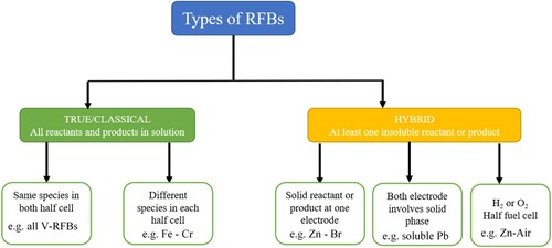
Mainly RFBs are of two types as shown in the chart below.
Out of the above-mentioned RFBs, four of the most promising RFBs for future ESS are selected for further discussion. The selection is based on the type of active materials incorporated in the RFBs, which are:
Vanadium -based redox flow batteries
Fe-based Redox flow batteries
Zn-based redox flow batteries
Mn-based redox flow batteries.
3.1. Vanadium-based redox flow batteries
Since the first successful presentation of vanadium-RFB by Skyllas-Kazacos et al. in 1986, VRFBs have emerged as the most promising electrochemical energy storage system owing to their suitability with a wide range of renewable energy sources, good stabilization, and smooth generation of output energy (Citation15). The VRFBs are mostly used for large-scale energy storage systems such as electrical peak shaving, load leveling, UPS coupled with renewable energy grids (like solar and wind power stations). The electrodes, membranes, and the electrolytes are the key parts of the VRFBs, which determine the overall performance of a VRFB, where the vanadium ions are used as the active materials in both electrolytes: anolyte and catholyte. A higher solubility characteristic of vanadium ions in sulfuric acid leads to an increase in the stability and energy density of VRFBs. The cell voltage of VRFB is 1.26 V, comparatively higher than other energy storage devices (Citation175). On the other hand, vanadium being a toxic and a rear earth metal, its availability and high cost limit the large-scale application of VRFBs. Many VRFB projects have been implemented in Japan, China, Austria, and Thailand over the last two decades (Citation176). The overall battery performance can be increased by modification of key materials like membrane, electrolytes, and electrode (Citation144–146), and optimizing the VRFB system and operation conditions (Citation177,Citation178). Some of the technical challengers that remain to be fully addressed in VRFBs are associated with the vanadium ions crossover through membranes, unwanted side reactions, self-discharge and capacity loss over repetitive cycles, poor stability, and electrolyte solubility, over heating that leads to change in operating conditions. Research groups primarily rely on mathematical modeling of VRFBs to understand the parametric sensitivity and conduct optimization studies by including diverse materials and battery/stack structure design. The all-VRFB is still considered the most efficient and most widely used RFB.
3.1.1. All-vanadium redox flow battery
All-VRFB is known to be the first invented vanadium-based flow battery. Due to the stability and longevity of all vanadium RFBs, they are suitable for large commercial applications. In addition, the environment potential of vanadium is less severe compared to the traditional lead-acid batteries (Citation179).
The All-VRFB utilizes a comparatively simple V2+/V3+ and VO2+/VO2+ redox couples for charge transfer that operates with high-cell and stack-energy efficiency in a dual electrolyte system ().
Figure 6. Classifications of existing RFBs.
The electrode reactions in the all-vanadium RFB shown in are as follows (Citation14):
(6)
(6)
(7)
(7)
(8)
(8)
Figure 7. Schematic representation and charge–discharge reaction of all-vanadium redox flow batteries.
The standard cell voltage for all vanadium RFBs can be calculated to be 1.26 V, which can be used in Nernst equation to calculate the cell voltage at a given pH value, temperature, and given concentrations of vanadium species:
(9)
(9) where
R = Universal constant
T = Absolute Temperature
F = Faraday constant.
However, the unwanted mixing of vanadium may occur in both sides of the cell due to crossover of vanadium ions through the membrane. This is known as self-discharge reaction, which can be represented as follows (Citation180).
In the negative half-cell, the diffusion of VO2+ and VO2+ from the positive side will react with V2+ and V3+:
(10)
(10)
(11)
(11)
(12)
(12)
In the positive half-cell, V2+ and V3+ diffused from the negative side will react with VO2+ and VO2+:
(13)
(13)
(14)
(14)
(15)
(15)
During the water decomposition, the hydrogen evolution reaction may occur and alongside an oxidation of carbon-based electrode may lead to CO2 evolution as well (Citation181). These two gaseous evolutions could adversely affect the overall efficiency of the system. One of the primary limiting factors of all-vanadium RFB is the higher cost of electrolyte. The electrolytes are generally prepared from the dissolution of vanadium pentoxide (V2O5) in sulphuric acid, and the optimization of vanadyl sulphate (VOSO4) solubility is a non-trivial process due to the concentrations of the major species being dependent on the composition and temperature (Citation182). Furthermore, to avoid the decomposition of the charged electrolytes, they must be stored in the isolation of air. The columbic efficiency, energy efficiency, and chemical stability of the all-vanadium RBF are comparatively better than others because of the use of same base material ions on both analyte and catholyte. However, because of the smaller size of vanadium ions cross over from electrode to electrode remains a challenge that decays the capacity during cycling, which requires further rebalancing to sustain the process. To overcome the limitations, VRFB researchers are trying to modify the VRFB by changing the materials or by introducing some additives into the electrolytes.
Zhao et al. studied a kW class of all-vanadium RFB stack consisting of 14 cells, with each cell having an electrode geometric area of 875 cm2 resulting in 1.14 kW of average output (Citation183). The system was successfully assembled by filter press type arrangement and showed a charge discharge current density of 70 mA cm−2. The configuration of 4 × 2 (serial × parallel) of the modified kW class stack module was the basic unit in the manufacture of 10 kW class VRFB stack with a maximum energy efficiency of 82.35% at a current density of 50 mA cm−2 showing an excellent performance to reveal the promising future of high efficiency VRFB technology for energy storage. Kumar et al. conducted an experiment with a single cell all-vanadium RFB fitted with three flow fields for a comparative study of the electrochemical energy conversion performance (Citation184). The serpentine, conventional, and inter digitated flow patterns were fitted in the VRFB; and additionally, for each flow field they also investigate the effect of electrolyte circulation rate. The RFB showed stable operation for 40 charge/discharge cycles. Ex-situ measurements of the pressure drop were carried out using water over a range of Reynolds numbers. As a result, the cell stack fitted with the serpentine flow filed shows the highest energy and voltaic efficiency with lowest pressure drop. The electrolyte flow was also found to be a factor influencing the performance of the system; 80% of high round-trip energy efficiency was obtained at the higher flow rate with the serpentine flow filed. This study shows an interesting correlation on the effect of electrolyte circulation on the performance of VRFB.
Electrolyte imbalance is one of the frequently reported challenges faced in the VRFB, which can be measured using a method reported by Ngamsai et al. (Citation185). A modified open circuit voltage (OCV) is attained by an addition of a middle half-cell in between the positive and negative half cells of the conventional OCV, that is used as the reference half-cell. This simple and low time-consuming technique is utilized to measure the oxidation state of vanadium in the electrolyte solution from the measured voltage in each side of the electrolyte. Thereafter, the basic electrochemical principles and the Nernst equation are applied to explain the cell voltage and oxidation state of vanadium. Different oxidation states of vanadium were seen in the experimental results and the predicted OCV was found to match with the experimental data.
Yue et al. developed an all-vanadium RFB consisting of a highly effective hydroxylated functionalization of carbon fibers as electrode (Citation186). Carbon fibers were made by ultrasonically hydroxylated carbon paper in mixed acids (H2SO4/HNO3, VH2SO4/VHNO3 = 3/1) in a Teflon-lined stainless-steel autoclave for different time periods at 80°C. The treated samples were used as positive and negative electrodes of VRFB. The hydroxyl group content changed drastically from 3.8% for the untreated sample to 14.3% for the carbon paper treated in mixed acids for 10h; and the treated showed high activity for the redox reaction of V(II)/V(III) and V(IV)/V(V). The modified VRFB showed an excellent performance with 91.3% of average voltage efficiency and 75.1% of average energy efficiency at a current density of 10 mA cm−2.
Another major issue reported in the VRFB is the thermal hydraulic effects and the influence of temperature on battery efficiency, which gradually impact the life span of the electrode material and the stability of the electrolytes. Xiong et al. developed a lumped model incorporating auxiliary pumps for the investigation of VRFB temperature response under different operating conditions (Citation187). The role of temperature and electrolyte flow rate on the battery electrical characteristics was also studied by the group in a 1-kW VRFB system. The thermal hydraulic model results were found to be in good agreement with the experimental data, indicating the pump power to be sensitive to the flow rates and hydraulic design. Under normal operating conditions for the stack design and selected electrolyte volume, the temperature in the tank and stack rose up to 10°C. The battery configuration was further modified to optimize battery efficiency showing an optimal flow rate of around 90 cm3 s−1. The model can effectively be used in the development of battery control strategy to achieve satisfactory thermal hydraulic performance and maximize energy efficiency.
3.1.2. Vanadium–bromine redox flow battery
Vanadium–bromine redox flow battery (VBRFB) is also known as the second-generation vanadium RFBs, where were developed to overcome the limiting energy density of the first-generation VRFB. The novel VBRFB consists of Vanadium (II)/Vanadium (III) in the negative half-cell and Br−/Br−3couplein the positive half-cell. Vanadium bromide, hydrochloric, and hydro bromide acids are typically used as the supporting electrolytes in both the cells, whereas carbon felt is a popular electrode for such systems. If both half cells are filled with vanadium bromide solution, cross-contamination can be greatly avoided. The system is suitable to handle a high concentration of vanadium due to better solubility, where vanadium concentration can be increased 3–4 M, resulting in a higher energy density of 50–70 Wh L−1 in the V/Br system. The higher solubility characteristics also allow VBRFBs to operate at low temperatures. The standard operating temperature of a V/Br battery is 45°C. The electrode reactions in the system of VBRFB are:
At positive electrode:
(16)
(16) At negative electrode:
(17)
(17) The VBRFB has some key advantages over the all-vanadium RFBs on account of an increased electrolyte energy density, which allows the V/Br system to operate with a decreased amount of vanadium with values as low as 50%. Vafiadis et al. conducted a study on evaluating the performance of ion exchange membrane used in such systems (Citation188), where they reported cation exchange membranes to be the best performing ion exchange membranes for VBRFB systems. During the battery cycle, the cation exchange membranes showed lower resistance losses. ABT3, Lo1854, and Mo4494 are the most common membranes reported for VBRFB systems.
As in the case of all vanadium RFBs, the VBRFBs are also not free from some practical challenges. The evolution of bromine gas at the positive half-cell during the charging time is a factor that affects the efficiency and stability of these systems. Grace poon et al. investigated the effect of adding two quaternary ammonium bromides (N-ethyl-N-methyl-morpholinium bromide (MEM) and N-ethyl-N-methyl-pyrrolidinium bromide (MEP)) to the positive and negative half-cell electrolytes of the V/Br system (Citation189). The inclusion of MEM and MEP effectively reduced the bromine vapor content generated during the electrochemical impedance spectroscopy (EIS), cyclic voltammetry (CV), and liner sweep voltammetry studies. Interestingly, the presence of MEM and MEP did not affect the mechanism of electrode reactions, making them promising additives for suppressing Br2 evolution to increase the VBRFBs efficiency.
The increase in electrochemical reaction improves efficiency in flow batteries. The electrochemical reactions are carried out on the surface of electrodes, so any surface modification of electrodes to improve surface area is expected to increase the efficiency of VBRFBs. Rui et al. prepared a few layered graphene oxide (GO) nanosheets with large specific surface area of 42.1 m2g−1 as per the hummers method to be used as electrodes in VBRFB (Citation190). CV results indicate that GO nanosheets with polymer binder (i.e. polyvinylidiene fluoride (PVDF) or sulfonated poly (ether-ether ketone) (SPEEK)) hybrids demonstrate a more favorable electro catalytic activity towards the Br−/Br3− and V3+/V2+ redox couples than the pure graphite electrode. Many oxygen-containing functional groups available in GO nanosheets generated more active sites to catalyze the redox reactions, which could have been the primary factor in the improved electrochemical performance of the modified SPEEK electrode. The electro catalytic activity of the VRFBs is primarily determined by the electro catalyst used in the system. Rui et al. further studies the performance of the Pristine graphite, multi-walled carbon nanotubes (MWCNTs), singe-walled carbon nanotubes (SWCNTs), and functionalized SWCNTs (FSWCNTs) with large number of oxygen-containing groups as electro catalysts for the Br/Br3redox couple reaction in the positive half-cell of the VBRFB system (Citation191). The FSWCNTs modified electrode for the Br/Br3 redox couple reaction showed an exceptional increase in the electrochemical activity compared to graphite, and a decreasing order in the electrochemical activities of the redox couple reaction was seen to follow as: FSWCNTs > SWCNTs > MWCNTs > graphite. The oxygen functional groups play a critical role in the electron transfer process by providing space for the active sites for the reaction and thus increase the effective electrode area. Even though VBRFBs have shown promising results, further process modifications related research is underway to tackle the limits of the system for a more acceptable large-scale application. Similar to VBRFBs, vanadium oxygen system has gained popularity in recent years that is discussed in the following section.
3.1.3. Vanadium oxygen redox flow battery
Kaneko et al., in 1992, proposed vanadium oxygen RFB (VORFB) system for the first-time as a promising candidate to replace the positive half-cell with an air electrode, with prospects of reducing the quantity of Vanadium needed for the cell reaction (Citation192). The use of air as the second redox couple decreases the overall system weight and increases the weight specific power output. However, the lack of reversibility in the positive electrode is seen as one of the main defects of the VORFB. This disability can be reduced by adding an electrolyte with suitable catalysts to act as a H2/O2 reverse fuel cell. This system shows high performance with less resistive membranes. In a standard VRFB, V(II)/V(III) redox couple is in the negative half-cell and the V(IV)/V(V) redox couple is in the positive half-cell. In the case of VORFB the negative side remains un-affected, whereas the positive side V(IV)/V(V) redox couple reaction is replaced by the oxygen reduction reaction, as follows:
At positive electrode:
(18)
(18) At negative electrode:
(19)
(19) With these redox reactions, a standard cell voltage of 1.49 V is and a current density up to 10 mA cm−2 could be obtained from the VORFB system, which results in a theoretical energy density of VORFB to be double than that of the VRFB. The system is also used in the ‘dual-circuit redox flow battery’ mode, which is combined with a separated catalytic hydrogen evolution reactor to take advantage of the conventional VRFBs (Citation193). According to the demand, the VORFB can be conventionally discharged or supply H2 by using a catalytic reactor. It consumes the proton during the hydrogen generation and creates a state of charge imbalanced. Under the charge imbalance conditions, a corresponding discharge of positive compartment is required to maintain proton to balance the charge of the system (Citation194). Herein, water oxidation can serve as a suitable reaction to provide the regeneration of the positive electrolyte (reduction of VO2+ to VO2+) as well as the protons. It does not possess a high potential oxygen evolution reaction. Additionally, the V–O2 cell can be converted into a circuit where a secondary flow cell provides a high rate of conversion and minimizes the energy requirements (Citation194). Authors reported the required additional energy of the system to be 140 mW cm−2 at a current density of 110 mA cm−2, which reduced the hydrogen evolution and improved the total efficiency of the coupled system to be between 42% and 62%. The VORFB system is not much studied and presents scope for further studies to improve the overall energy efficiency at a low cost of the overall RFB system.
3.1.4. Vanadium–manganese redox flow battery
Vanadium–manganese redox flow battery (VMRFB) is another interesting type of RFB which recently has gained popularity with its prospects for being used for commercial purposes. Here, manganese ions are added to increase the energy density of the VRFB system. The Mn (II)/Mn (III) ions in positive electrolyte considerably affect the performance and the life span of RFB system. The Mn (II)/Mn (III) ions have high redox potential with higher discharge voltage resulting an increment of 47% of initial density from 20 to 31 WhL1. However, the precipitation of MnO2 reduces the energy density of the Vanadium–Manganese system beyond the 10th cycle. In addition, the MnO2 is also formed by the conversion of Mn (III) in the positive electrolyte during the charging process. Lee et al. reported the particle size of the MnO2 to decrease and the number of vanadium ions permeating to the positive electrolyte to increase as the number of cycles increases in VMRFB (Citation195). As a result, in the reduction reaction MnO2 could participate without precipitating and increase the energy density. MnO2 is produced as indicated by the reaction below:
(20)
(20) The result indicates the possibilities of controlling the particle size of MnO2 and dissolution of Mn ions that can be used in the positive electrolyte. Park et al. demonstrated vanadium–manganese/vanadium–manganese multiple redox couple hybrid system to produce outstanding energy density and display superior performance compared to the All-VRFB (Citation196). The V–Mn/V–Mn system holds a much higher energy density than the V/V RFB due to the multiple redox reactions involving both V and Mn ions; additionally, the operating cell potential also increases owing to the high standard potential of the Mn (II)/Mn (III) reaction. As compared with the V/V system, the discharge density of V–Mn/V–Mn system is consequently increased by 66.8%. The electrolytes in the V–Mn/V–Mn system are not simply a mixture of V and Mn, it has some unique advantages. During the charging process, the disproportionation reaction occurs to form MnO2, which then is reduced in the presence of V ions. The small particles of MnO2 flow into the cell with electrolytes and change into Mn ions. Experiments demonstrate the reversibility, longevity, and stability of the VMRFB systems to greatly improve on account of these phenomena (Citation165). For ease of accessibility and comparison, selected vanadium-based flow batteries are characterized in .
Table 4. Characteristics of selected vanadium flow batteries.
3.2. Iron-based redox flow batteries
Iron is the most attractive option as a battery material due to its environment friendliness, cost, and abundant availability. NASA did some initial research on the development of iron–chromium (Fe–Cr) batteries in 1980 that was further expanded to several redox couples (Citation197), parallel to that Skyllas-Kazacos et al. reported the invention of the All-VRFB (Citation15), where four different ions of the same element were used as the active materials, making the VRFBs easier to fabricate compared to the Fe–Cr system. shows the characterization of IRFBs. However, with a growth in application accompanied by scarcity and high cost of vanadium, more emphasis is given to developing alternatives to all, where iron-based RFBs are the natural preferred choice. Some relevant iron-based RFBs are explained in the following sections.
Table 5. Characterization of different types of IRFBs.
3.2.1. All-iron redox flow batteries
Savinell et al. reported a critical development of iron-based RFBs, which was like all vanadium RFBs, except it consisted of three oxidation states of iron (Fe, Fe2+, and Fe3+) (Citation198). The all-iron RFB consists of the positive electrode having the redox couple of Fe3+/Fe2+ and the negative electrode consisting of the redox couple of Fe2+/Fe with an open circuit voltage of 1.2 V. All-iron RFB is hybrid RFB where the power densities and energy densities are not independent because of the plating of Fe2+/Fe happening at the negative electrode. A typical all-iron RFB model contains two tanks of negative and positive electrolyte, where the positive electrolyte is made of the mixture of ferrous and ferric chloride and negative electrolyte is the ferrous chloride. The electrolyte solution kept in the external tank greatly influences the performance and overall cost of the all-iron RFBs. In each battery, the residual energy is represented by a ratio of anolyte to catholyte solution which is a function of state of charge. The cost of all-iron RFB is directly proportional to the cost of metal slats used as electrodes in the electrolyte (Citation199); with graphite electrodes being commonly employed, nevertheless, in some cases only the iron electrode is also reported to be used. It is generally agreed that the graphite electrode only provides a surface for electrons to enter and pass to the electrolytes, it does not have a role in electrochemical reaction. Ammonium (NH4Cl) and boric acid (H3BO3) are chemical additives used as supportive electrolytes to reduce the resistivity of the electrolyte and to decrease the hydrogen evolution. Following reactions are supposed to take place in the all-iron RFBs:
(21)
(21)
(22)
(22)
(23)
(23)
Gong et al. explained the electrochemical reactions in all-iron RFB system as in (a), while suggesting some challenges associated with cross contamination of metal ion (Citation200). Therefore, they constructed an all-iron RFB by combining iron-triethanolamine redox pair, i.e. [Fe(TEOA) OH]−/[Fe (TEOA)(OH)]2–) and iron–cyanide redox pair, i.e. (Fe (CN)63–/Fe (CN)64–) with a formal potential difference of 1.34 V (b) between the redox pairs(Citation200). (c and d) shows the operation of all iron RFB with a cell voltage of 1.3 V and an outstanding performance with long term stability. Yu et al. developed a low-cost all-iron RFB system consisting of FeSO4 electrolyte, incorporating a microporous membrane along with a glass fiber separator (Citation201). To overcome the low solubility of FeSO4 in water, they also used 0.1 M 1-ethyl-3-methylimidazolium chloride (EMIC) as a supporting electrolyte that resulted in FeSO4 solubility of 2.2 M. Furthermore, using DFT calculations they demonstrated that EMI+ can strengthen the interaction between sulfate anions and water molecules. Both anode and cathode reactions can be performed without an active pH gradient between them, based on the electrolyte composition, to eliminate the need for expensive ion exchange membranes. The system can be operated stably at a current density of 20 mAcm−2 for more than 800 cycles. The projected cost of the FeSO4/EMIC RFBs is $ 50 per kWh (Citation202), which is very low due to the inexpensive micro porous membrane and the low-cost active material. These features make the all-iron RFBs a promising stationary storage system for storing highly concentrated renewable energy in an economical manner. Zhen et al. designed a non-aqueous all-iron redox flow battery (NARFB) based on iron acetylacetonate (Fe(acac)3) anolyte and N-(ferrocenylmethyl)-N, N-dimethyl-N-ethyl ammonium bis (trifluoromethane-sulfonyl) imide (Fc1N112-TFSI) catholyte, and an anion exchange membrane of FAP-375-PP; resulting in an open circuit voltage of 1.34 V (Citation203). The resultant battery demonstrated a high cycling performance and rate capability due to the high electrochemical activity of the active species. Over 100 cycles, the system maintained a coulombic efficiency (CE) of 98.7%, voltage efficiency of 84.5%, and the energy efficiency (EE) of 83.4% at a current density of 10 mA cm−2. The addition of the mixed reactant electrolyte (in both anolyte and catholyte) showed a further increase in voltage efficiency up to 89.2% and the energy efficiency up to 85.2%. Nonetheless, the system showed some capacity decay trend and requires further studies to be suitable for a sustainable performance in future.
3.2.2. Iron–chromium redox flow battery
Iron–chromium RFB (ICRFB) was investigated at the early stages of the RFBs development because of the low cost of the electrolyte capable of generating a cell potential of 1.2 V, which makes them still relevant, suitable, and competitive for large-scale energy storage applications. The first true RFB is considered by the ICRFB. Abundance of iron and chromium chlorides as redox active materials makes ICRFB a true frontrunner in RFB market (Citation23). The cost of the raw materials of chromium and iron is estimated to be $17 kW h−1, making ICRFBs most promising cost-effective redox flow batteries. Carbon felt can be used as electrodes and ion-exchange membrane can effectively separate the two components in most of the ICRFB to provide 1.18 V of standard voltage based on following redox reactions:
Figure 8. (a) Schematics of all-soluble all-iron RFB consist of iron−triethanolamine redox pair, (b) cyclic voltammogram of [Fe(TEOA)OH]−/[Fe(TEOA)OH]2− and Fe(CN)63−/Fe(CN)64− in NaOH solution, (c) polarization curve of all Fe RFB, (d) stability run for 110 cycles to test the cell voltage at 40 mA cm−2 and the corresponding performance parameters (VE, CE, EE, and volumetric capacity), (e) discharge capacity and columbic efficiency of 0.67 M iron(II) sulfate, 0.33 M AQDS, and 2 M sulfuric mixed electrolyte at 200 mA cm−2, (f) power density of symmetric cell with 5% Nafion MWCNT-felt 1 M iron(II) sulfate and 2 M sulfuric acid on the positive side and 1 M iron(II) sulfate with 2 M sulfuric acid and 0.5 M AQDS (Citation200,Citation209).
![Figure 8. (a) Schematics of all-soluble all-iron RFB consist of iron−triethanolamine redox pair, (b) cyclic voltammogram of [Fe(TEOA)OH]−/[Fe(TEOA)OH]2− and Fe(CN)63−/Fe(CN)64− in NaOH solution, (c) polarization curve of all Fe RFB, (d) stability run for 110 cycles to test the cell voltage at 40 mA cm−2 and the corresponding performance parameters (VE, CE, EE, and volumetric capacity), (e) discharge capacity and columbic efficiency of 0.67 M iron(II) sulfate, 0.33 M AQDS, and 2 M sulfuric mixed electrolyte at 200 mA cm−2, (f) power density of symmetric cell with 5% Nafion MWCNT-felt 1 M iron(II) sulfate and 2 M sulfuric acid on the positive side and 1 M iron(II) sulfate with 2 M sulfuric acid and 0.5 M AQDS (Citation200,Citation209).](/cms/asset/039418dc-c4ba-4afd-bdc9-1290ae0db080/tgcl_a_2302834_f0008_oc.jpg)
Positive electrode:
(24)
(24) Negative electrode:
(25)
(25) Overall:
(26)
(26)
The ICRFBs are among the most frequently studied systems over the past decades for energy storage applications (Citation172,Citation173). Because of the rapid kinetics of the Fe (II)/Fe (III) redox reaction, at the positive side of the carbon felt, enhancements are only needed for the electrochemical kinematic of Cr (II) / Cr (III) redox reaction by using suitable catalyst at the negative side of the cell. A catalyst generally increases hydrogen evolution reaction as the hydrogen ions are more easily reduced than the Cr (III). Hydrogen evolution serves as a competitive reaction and causes a decrease in coulombic efficiency leading to capacity decay. To reduce this issue, some researchers have tried depositing Bi and Au–Ti catalysts on the electrode surface to increase the electrochemical kinetics of Cr(II)/Cr(III) redox reaction and successfully reduced the hydrogen evolution reaction (Citation204). Electrochemical kinetic constant for Fe2+/Fe3+ redox couples on cathode side is of 8.6 × 10⁻² cm s−1, whereas the anode side redox couple of Cr2+/Cr3+ with bismuth catalyst shows a kinetic constant of 1.35 × 10⁻³ cm s−1, putting the ICRFBs at par with that of the V2+/V3+ redox couple (Citation205).
The charge–discharge performance of the ICRFBs is based on the effect of the design parameters. Zeng et al. investigated the key design parameters influencing the battery performance of iron–chromium based RFBs (Citation206). Catalyst loading, membrane thickness, electrode compression ratio and electrode pretreatment are the investigated parameters in their study. As per the results, (i) within the range of 0.52–10.45 mg cm−2, the bismuth catalyst loading has insignificant effect on the battery performance, (ii) utilizing NR-211membranewith a 62.5% of high electrode compression ratio, the system achieved a high operating current density of 480 mA cm−2 at an energy efficiency higher than 80%, (iii) the system worked at temperatures of 25°C and 65°C, and the dominant loss was identified to be ohmic loss rather than kinetics loss, (iv) the energy efficiency of the system improved after a moderate oxidative thermal pretreatment of the electrodes, whereas the electrode modified with harsh pretreatment conditions deteriorated quickly.
The bismuth catalysts used in ICRFBs are commonly prepared by adding small amount of Bi3+ in the electrolyte and synchronously depositing the metallic particles onto the porous electrode surface, where a uniform catalyst distribution is ideally sought (Citation207). Zeng et al. investigated the effects of flow field designs on catalyst electrode position and battery performance. They compared the inter digitated flow filed (IFF) against the Serpentine flow filed (SFF) and reported that the IFF forces the electrolytes to flow through the porous electrodes in between the neighboring channels and increases the transport of species during the process of iron/chromium redox reaction and catalyst electrode position. This process enables a more enhanced distribution of catalyst and a higher mass transport limitation (Citation207). The system with IFF shows an outstanding performance, which shows an energy efficiency of 80.7% at a higher current density of 320 mA cm−2. The energy efficiency of modified system with IFF was realized to be 8.2% higher than that of ICRFB with SFF. This design modification achieves an excellent performance with low-cost active materials, showing great promise for stationary energy storage devices.
The concentration of the electrolytes also influences the performance of the ICRFBs, as reported by Wang et al. using a series of electrolytes with x M FeCl2 + x M CrCl3 + 3.0 M HCl (x = 0.5, 0.75, 1.0, 1.25) and 1.0 M FeCl2 + 1.0 M CrCl3 + y M HCl (y = 1.0, 2.0, 3.0, 4.0) (Citation208). As per the results, while increasing the concentration of FeCl2, CrCl3, and HCl, the viscosity of electrolyte increased, whereas the conductivity decreased with an increase in the concentration of FeCl2 and CrCl3 but the addition of HCl showed an increase in conductivity trend. The electrochemical system performed well with electrolyte consisting of 1.0 M FeCl2, 1.0 M CrCl3, and 3.0 M HCl generating a synergistic effect in conductivity, viscosity, and electrochemical activity. ICRFB with optimized electrolyte system showed an outstanding performance with an energy efficiency of 81.5% and the coulombic efficiency of 97.4% at a current density as high as 120 mA cm−2.
3.2.3. Iron–sulfate redox flow battery
Iron–sulfate redox flow battery is a relatively new type of RFB consisting of iron sulfate and anthraquinone disulfonic acid (AQDC) that shows the outstanding electrical performance, chemical durability, and the capacity retention (Citation209). The cost of the system development is also considerably low as the iron sulfate is a waste material in steel industries resulting in the estimated cost of the active material to be $66/kWh. Performance wise, (e) shows a very stable operation of iron sulfate system resulting in a negligible capacity fade rate of 7.6 × 10⁻⁵% per cycle in a 500-cycle test (Citation209). An average columbic efficiency of 99.63% is shown by a symmetric cell using graphite felt electrodes. The graphite felt was further modified with multi-walled carbon nanotubes (MWCNTs), resulting in outstanding power density of 194 mW cm−2 as shown in (f). Nonetheless, major voltage losses were seen that are attributed to ohmic resistance of the electrode and electrolytes. The lower cell voltage of the system is like the VRFBs, however, the iron-AQDS RFB shows a better stability, cost-effectiveness, and scalability making it a promising system for future energy storage system (Citation197).
The reaction mechanism in the iron sulfate – AQDC is expected to be as follows:
3.3. Zinc-based redox flow batteries
The development of zinc-based RFBs consisting of zinc bromine and zinc chlorine is reported as early as 1970s (Citation210). The zinc redox flow batteries (ZRFBs) have comparatively higher energy density than others, fast kinetics of electrochemical reactions and low materials cost, which are the primary factors driving the research in zinc-based RFBs as noted by frequent reports on this system over the last two decades in both academic and industrial sectors (Citation211). Zinc–bromine, zinc–cerium, zinc–ferri cyanide, zinc–nickel, and zinc–polymer are some of the common types of Zn-RFBs, where the zinc–bromine system is primarily targeted for the industrial purpose whereas the zinc–ferri cyanide is relatively less studied and requires further research. However, major limitations in Zinc RFB are associated with the formation of zinc dendrites, shaped formation of electrodes, and competition with hydrogen evolution reaction. Even though issues like zinc electrode deposition, dissolution, and the formation zinc dendrite can be, to some extent, controlled by adding suitable electrolyte additives; further research is required to fully understand the origin of dendrites formation and limit their growth. A well-understood design strategy can make the zinc RFBs a good performer by improving the lifecycle of the battery and maintaining a stable concentration of Zn (II) ions (Citation212). summarizes the different types of zinc-based redox flow batteries investigated in this study.
Table 6. Different types of zinc-based redox flow batteries investigated in this study.
3.3.1. Zinc–bromine redox flow battery
Zinc–bromine redox flow battery (ZBRFB) is reported to have been developed by Exxon in 1970s (Citation213). The ZBRFB can be considered a type of hybrid RFB as much of the energy is stored by plating zinc metal as a solid onto the anode plates in the electrochemical stack during the charging process. The electrode area (stack size) and the size of the storage tanks of the electrolyte determine the total energy storage capacity of RFBs. The ZBRFB consists of not fully decoupled ratings of power and energy. Micro-porous polyolefin membrane is a commonly used separator in the system. The negative side (anode) contains purely water-based electrolytes, whereas the cathode side electrolyte contains an organic amine compound to hold bromine in the solution. Bromine has a very limited solubility in water but reacts with the organic amines in the catholyte to form a dense phase. During the charging cycle, the anode side of the carbon-plastic composite electrode gets plated with a thick metallic zinc film, whereas the bromine ions undergo oxidation to form bromine gas, which then evolves on the other side of the membrane.

During the discharge cycle, the anode plated with zinc metal oxidizes to Zn2+ ion and it gets dissolved into the aqueous anolyte, and two released electrons perform the work in the external circuit. Then these electrons return to the cathode and reduce the bromine molecules into bromine ions, which is soluble in aqueous catholyte solution. In the catholyte solution, bromine is decomplex from the amine and converted into two bromide ions balancing the Zn2+ ions resulting in a zinc bromide solution (Citation214). Whenever the chemical activity increases, the electric current will also increase along with the concentration of bromide ion and zinc ion in the electrolyte tank. A reasonable range of 65–75% net DC–DC efficiency is reported in zinc–bromine RFB (Citation215); however, the toxicity of the bromine is the primary issue facing such flow batteries, which could be addressed, to some extent, by suitable additives that generally tend to be highly expensive (Citation216). The complex bromine also had temperature stability issues, since the temperature must be kept below 50°C. During both charging and discharging only lower areal power (<0.2 W cm–2) occurs.
Qinzhi et al. improved the energy density of the ZBRFB by designing a novel single flow zinc–bromine RFB by using a semi-solid positive electrode to avoid liquid storage tank and pump on the positive side (Citation235). This arrangement resulted in 82% energy efficiency (EE) and 92% coulombic efficiency (CE) in the single flow batteries for over 70 cycles at a current density of 20 mA cm−2, which is comparatively better than the traditional zinc–bromine flow battery. The zinc–bromine RFB is a promising system with low cost; however, the system suffers from some difficulties like low conductivity of the electrolyte, high polarization in the positive electrode, and low power density. Wu et al. modified the electrolytes by adding chloride salts like KCl and NH4Cl as supporting electrolytes to increase electrolyte conductivity and used treated thermally graphite electrodes to improve the electrocatalytic activity(Citation236). Without using any electrolytes, the system showed an energy efficiency of 60.4%, whereas after the addition of 4M NH4Cl as supporting electrolyte, the system showed an energy efficiency of 74.3% at a current density of 40 mA cm−2. This modified electrolyte in the Zn/Br system with thermally treated graphite felt showed an energy efficiency of 81.8% at same current density of 40 mA cm−2. The surface properties of the positive electrode of the Zn/Br RFBs are related to the performance of the system, and any modification of surface electrodes are expected to result in an enhancement in the performance of the system. As per a study by Archana et al., a modified graphite electrode with thermal and plasma treatment under oxygen and nitrogen atmosphere resulted in a higher electrode surface area and increased defects density with the generation of oxygen functional groups and N-doped surfaces, respectively (Citation234). The increased surface area and the surface functional groups influenced the performance of the cell, and whenever the concentration of the organic polybromide phase was detected to be higher, the surface oxygen functionalization proved to be a decisive factor for an enhanced performance of the system (Citation234).
3.3.2. Zinc–cerium redox flow batteries
Another variation of Zn-based RFB systems was developed by Plur ion Inc. (UK) by incorporating cerium into the system to take advantage of energy storage properties of cerium-based compounds (Citation237). Zinc and cerium are particularly advantageous materials for their energy storage applications as their standard electrode potentials have larger differences in aqueous media. This system has a high energy density and a thermodynamic open circuit voltage of 2.4 V. The selection of the material is correctly necessitated by the large potential difference and reducing the secondary reactions such as oxygen and hydrogen evolution. The electrode position and dissolution of zinc on a planar carbon/polyvinyl-ester composite material is the key electrode reaction to take place on the negative electrode.
(27)
(27) While the hydrogen evolution can also take place on this electrode
(28)
(28) The oxidation process of Ce (III) is the primary reaction during the charging process, whereas the reduction of Ce (IV) is the targeted reaction during discharge cycles, both take place at the positive electrode. Depending on the background electrolyte, with respect to Ag/AgCl, the positive standard electrode potential lies between 1.28 and 1.72 V.
(29)
(29) While oxygen evolution can also take place:
(30)
(30) The overall reaction ZCRFB is
(31)
(31) Methane sulfonic acid is used as a solvent for both zinc and cerium ions. While its conductivity is comparable to that of the hydrochloric acid, it engenders a lower risk of corrosion compared to other mineral acids while at the same time maintains a high degree of stability (Citation185). It also essentially makes the preparation of electrolytes easier due to the high solubility of cerium in methane sulfonic with the solubility limits of Ce (III) and Ce (IV) ions in methane sulfonic acid being 1 mol dm−3. Zinc also has a high solubility of 2.16 mol dm−3 in the same acid (Citation219). These favorable conditions make the ZCRFB a promising system to store large amounts of energy commercially with an added advantage of high thermodynamic open circuit voltage compared to other aqueous RFBs.
Amini et al. studied the life cycle of the zinc–cerium RFB with the help of titrimetric analysis, monitored the potential of half-cell electrode, and measured the concentration of Ce (IV) and H+ ions on the positive and negative sides respectively (Citation238). During the discharging cycle of the system, they observed an incomplete reduction of Ce (IV) to Ce (III), and Ce (IV) ions were accumulated on the positive side due to the limitation of charge efficiency by the zinc redox reaction at 25 mA cm−2 of current density. The negative sides of battery consist of proton concentration that increased over the cycles. This effect is expected to enhance the hydrogen evolution rate on the negative side and contributes to Ce (IV) precipitation on the positive side. These combinations of the two phenomena could lead the cell to capacity fade and failure with time. However, a replacement of Nafion 117 cation exchange membrane with anion exchange membrane (AEM) can help in overcoming this limitation. In the presence of Ce (IV), a chemically stable Fap-375-PP anion exchange membrane was used which resulted in the concentration of proton on the negative side to be reduced and thereby the life cycle of the system also increased. The zinc–cerium RFB with fabricated AEM are a new promising dimension in the stationary energy storage system. Xie et al. studied the performance of Ce3+/Ce4+ redox couple in the methane sulfonic acid electrolyte to use in the RFB technology (Citation239). The linear sweep voltammetry, rotating disc electrode, cyclic voltammetry, and chronoamperometry methods were used to evaluate the electrochemical properties of the Ce3+/Ce4+ in methane sulfonic acid electrolyte. A standard rate constant of the Ce3+/Ce4+ redox reaction on graphite electrode in methane sulfonic acid was found to be 4.06 × 10⁻⁴ cm s–1, whereas the diffusion coefficient of Ce3+ and Ce4+ in methane sulfonic acid electrolyte was 5.87–6.15 × 10⁻⁶ cm2 s–1 and 2.56–2.68 × 10⁻⁶ cm2 s–1 respectively. Overall, an energy efficiency of 74.8% was observed in the cerium–zinc RFB making the Ce3+/Ce4+ system suitable and competitive for RFB technology.
3.3.3. Zinc–iodine redox flow batteries
Due to a high-energy density, the development of zinc–iodine redox flow battery (ZIRFB) was a promising energy storage system, nonetheless, the practical usage suffered from some grave limitations like poor stability, high cost and the low efficiency, which requires considerable efforts to make it a feasible system of practical considerations. Mousavi et al. thoroughly studied the zinc iodine RFBs system to improve the cyclic stability, performance and reduce the chemical cost by developing an ammonium-based electrolytes (ammonium chloride) supported ZIRFB battery (AC-ZIFB) to effectively utilize the triiodide/ammonium iodide redox couple for energy storage/generation (Citation233). The system showed a high coulombic efficiency of 99%, energy efficiency of 80%, energy density of 137 Wh L−1 and a cycle life of 2500 cycles. Also, the cost of the chemicals reduced by11 times compared to the conventional ZIRFB. The reaction held at ZIRFB is
Anode:
(32)
(32) Cathode:
(33)
(33) Mousavi et al. further reported a capacity fade as a main issue faced by the ZIRFB, which influenced the electrochemical performance and electrolytic properties (Citation240). Both sides of the porous separator consisted of differential hydraulic pressure that led to a massive electrolyte transport from catholyte to anolyte via convection (Citation240), generating a (poly) iodide accumulation on the negative side as cycling proceeds. This accumulation of (poly) iodide caused the capacity fade of the ZIRFB as indicated in (a). To reduce the capacity fade, the researchers selected a way of regulating the induced convection by balancing the hydraulic pressure with the help of adjusting electrolyte flow ratios as indicated in (b). As it can be seen in (c), the major effect of unbalanced hydraulic pressure was closely observed for the first 10 cycles and is highest for the same flow rate (1:1), whereas the electrolyte volume becomes more stable when the flow rate was increased to the ratio of 1:7 and 1:5. (d) shows the performance of ZIFB with different flow rates and it can be concluded that higher electrolyte flow rate ratio further improves the EE and VE of the RFB. This performance shows much higher efficiency than previously reported values for ZIRFB. A zinc negative electrode of an aqueous RFB system shows a high energy density, but the potential for achieving longevity and high-power density is difficult due to the dendrites growth at the anode that affects the overall efficiency of the RFB. The design of flow field is expected to influence the zinc deposition and the performance of ZIRFB as reported by Hosseinabad et al. (Citation241), who proposed a new cell design for zinc-iodide flow battery with a narrow gap between electrode and membrane. In the direction of current flow, a fraction of the flow passes through the porous felt electrode and some of the electrolyte flows over the surface of electrode. The flow battery was tested for under 40 cycles, and results were compared to the conventional flow field designs, resulting in the discharge energy density, the power density, and the efficiency of the battery showing much improvement with the narrow gap arrangement between electrode and membrane (Citation241). Based on scanning electron microscopy and optical profilometry study of the zinc deposition morphology, a thinner zinc deposit with lower roughness was observed due to the flow through the electrode.
Figure 9. Illustration of the unbalance of the hydraulic pressure in ZIFB, (b) the modified cell design by balancing the pressure on both sides by adjusting the flow rate 10 1:7, (c) the change of volume on anolyte and catholyte over different cycle number at different flow ratio. ZIFBs cell performance (d), CE, (e) VE, (f) EE at a current density of 80 mAcm−2, (g) performance of Zn–Mn flow cell at different current densities, (h) cell stability and discharge capacity of Zn–Mn cell at a charge capacity of 2.34 Ah L−1(Citation240).
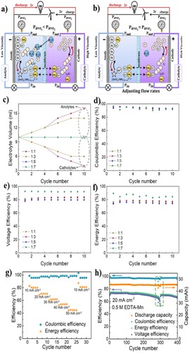
3.3.4. Zinc–manganese redox flow battery
Zinc–manganese redox flow battery (ZMRFB) is an emerging and low-cost environment friendly type of energy storage system, where the economical manganese redox couples ensure a similar cell voltage as vanadium systems (Citation242). Additionally, the Zn–Mn system shows higher energy density characteristics utilizing Mn (II)/Mn (III) manganese ions in the system. During the charging cycle, the oxidation occurs in the positive electrolyte, and then MnO2 is formed through the disproportionation reaction of Mn (III). If theMnO2 precipitation is not reduced during the discharge cycle, it affects the energy density and the overall efficiency of the system. Carbon felt is commonly used as the electrode in the system, where the precipitated MnO2is deposited causing instability in ZMRFB (Citation218). In a study by Yu et al., the researchers used EDTA-Mn as the positive electrolyte in highly reversible Zn–Mn flow battery (Citation218). Based on an initio calculation, the EDTA provides a strong ligand field for Mn2+ in aqueous solution, due to which the carboxyl/amino groups form bonds with Mn2+ and rearrange the bonded water in the solvation structure of Mn2+. These effects lead to an improvement in both electrochemical and material characteristics and effectively inhibit the disproportionation reaction of Mn3+ without forming any deposited MnO2 on carbon felt electrode (Citation218). The modified Zn–Mn flow battery with EDTA-Mn is shown in (g) and displays an outstanding performance with a high columbic efficiency value of above 95%, operated at 10–50 mA cm−2, while realizing a superior cycling stability over 300 cycles at 20 mA cm−2 affording 98% columbic efficiency and 75% energy efficiency (h).
The mechanism of reaction held in the manganese is shown below:
Charge process:
(34)
(34)
(35)
(35)
(36)
(36)
Discharge process:
(37)
(37) The primary advantage of the ZMRFB can be realized in the field of large-scale stationary energy storage system because of the low-cost, large-scale availability, and safety of zinc and manganese-based materials. As per are port by Liu et al, who designed ZMRFB with highly crystalline spinel-type λ-MnO2 as cathode (derived from LiMn2O4 via mild acid treatment), and utilized 1M Li2SO4 + 1M ZnSO4 as electrolytes in the system (Citation242). The λ-MnO2 cathode showed two high discharge voltages of 1.97 and 1.81 V, whereas the specific capacity of the system was found to be 128 mAh g−1 (Citation242). The combined form of modified system showed an excellent performance with high-capacity retention of 83% with 1000 continuous cycles while maintaining an energy efficiency of 98%. For the improvement of the performance of the ZMRFB, Naresh et al. investigated a new electrolyte composition with modified membranes (Citation243). The results indicated sulfate-based electrolyte compositions and a daramic membrane modified with polyacrylonitrile (PAN) as a pore filling agent to perform outstandingly at various operating conditions of the system (Citation243). The cell combined with this modified electrolyte and electrode shows excellent overall performance with the energy efficiency of the system to be 75.45%, and up to 40 mA cm−2 the modified membrane experienced an improved performance. Additionally, over 100 cycles, the system with PAN filled daramic membrane achieved a consistent performance. These results show the promise of the daramic membrane and sulfate-based electrolyte as a suitable system for ZMRFB.
3.4. Manganese-based redox flow batteries
Manganese-based RFB utilizes manganese ions to store large-scale energy for commercial purposes. With Mn being the 12th most abundant element in the earth’s crust without any significant geographic restrictions, its utilization can help in developing cost effective RFBs (Citation223). As discussed earlier, Mn has been utilized as active material in vanadium and zinc-based redox flow batteries to increase their energy efficiency. The manganese redox couple ensures similar cell voltage as vanadium, while having a higher redox potential. Mn (II)/Mn (III) ions are the commonly used of which the Mn (III) in the positive electrolyte converts to MnO2 during the charging cycle, and this precipitation does not get reduced during the discharge cycle; and affects the energy density and the overall efficiency of the system. The formation of MnO2can be understood with the following equation (Citation195):
(38)
(38) As discussed in the previous section, there are few strategies for flow cell design that can be adopted to minimize MnO2 precipitation. Furthermore, in the next section we have discussed RFB based on utilizing other materials alongside manganese for efficient management of the overall flow battery performance. Such systems include titanium-manganese RFB and hydrogen-manganese RFB.
3.4.1. Titanium–manganese redox flow battery
The manganese and titanium redox couple have low cost and have abundant chemical availability to make the titanium-manganese system a preferred choice for storage applications. The cell voltage of the Ti–Mn system is equivalent to the All-VRFB. Due to the possibility of MnO2 precipitation, the titanium and manganese mixed solutions are used as positive and negative electrolytes (Citation161). The disproportionation reaction of Mn (III) is suppressed in the presence of Ti (IV) ions in the positive electrolyte, which also suppresses the particle growth of formed MnO2. The nanoparticles of MnO2 contribute to excellent flow-ability and electro-active performance making Ti–Mn system a highly stable, along with reducing the crossover of electro-active species in the system due to the usage of same electrolyte on both half cells (Citation224).
The electron transfer reaction of the system is represented as follows:
(39)
(39)
(40)
(40) The potential difference between these two reactions is around 1.41 V, where the Ti3+ and TiO2+ form the Ti (III)/Ti (IV) redox couples in concentrated non-oxidizing strong acids. During the discharge period, Ti3+ is transformed to TiO2+ in the negative half-cell. The manganese ions, Mn2+ and Mn3+, are the existing form of Mn (II)/Mn (III) redox couple respectively, where the Mn3+ changes into Mn2+ in the positive half-cell during the discharge period. The chemical stability of the Mn3+ in aqueous solution is very low, literally it is unstable, and it transfers to disproportionate to Mn2+ ion and Mn dioxide. During the charging period, the manganese dioxide precipitates in the positive electrolyte, resulting in some efficiency issues, which in some cases, could lead to fatal problems for the RFBs. Dong et al. studied a mixture of Ti (IV) and Mn (II) in both the half-cell electrolytes of Ti–Mn system, with an objective of reducing the disproportionation reaction of Mn (III) (Citation161). In a single cell test, energy density of 23.5 kWh m−3 was obtained, while maintaining an excellent flow-ability and electro-active performance of the system due to the contribution of manganese dioxide nano particles. In this study, they found that the disproportionation of Mn3+ ions changed by mixing with TiO2+ ions in sulfuric acid solution and the TiO2+ ions suppressed Mn3+ ions disproportionation reaction (Citation161). The performance of Ti–Mn system is comparable to the All-VRFB, making it a promising and economic RFB alternative system for the future energy storage. Nan et al. introduced a MnO2-based slurry flow battery (CMSFB) for the first time to improve the life cycle of Mn-RFB, where small-sized MnO2 acted as redox active materials (Citation225). The system benefits from the electrostatic interactions of the homogeneously dispersed MnO2 particles in the electrolyte during the charging process, and sufficient contact with the reaction sites of the electrode during the discharge process. As per the results, the CMSFB system showed a Coulombic efficiency and energy efficiency of 99% and 85%, respectively, at a current density of 40 mA cm−2 without any capacity delay for over 1000 cycles (Citation226). This developed cell offers an interesting and promising future for titanium–manganese towards for stationary energy storage system.
3.4.2. Hydrogen–manganese redox flow batteries
In manganese-based RFBs, a large pressure drop occurs because of the formation of solid, insoluble MnO2 particles, which reduce the mass transport due to the electrode and flow field blocking (Citation227). A drop in the concentration of active species in solution and an irreversible decay in RFB power and capacity are also caused by MnO2 formation (Citation228), whereas in liquid–liquid RFB configuration, the crossover of the active species poses considerable challenges for RFBs. These complications led researchers to configure a new setup for manganese-based RFB by employing liquid–gas configurations (Citation229). Because of the hybrid design featuring multiple phases with vast difference in the densities of the liquid and gas, they can easily be separated. Hydrogen is a natural choice for the gaseous species to be used as an active component in most the systems. In this hybrid RFB, the manganese ions in the positive half-cell and the H2 in the negative half-cell constitute the cell reactions as below:
(40)
(40)
(41)
(41) According to a study of Rubio-Garcia et al., the rebalancing of the electrolyte is easier by pumping the liquid back or H2 top up from a cylinder in the hydrogen–manganese RFB (Citation227). When the hydrogen–manganese system is compared with the hydrogen/bromine system, the hydrogen system has advantages because of the usage of manganese-based liquid electrolytes that allows preserving the activity of metal catalysts at the gas side. This combination of hybrid battery system shows outstanding performance, excellent longevity, high round trip efficiency, and impressive power output (Citation227). Additionally, the hydrogen/manganese RFBs are economically suited for large-scale energy storage applications.
4. Current trends
RFBs have emerged as a preferred choice for large-scale energy storage devices. Owing to their suitability in integration with intermitted power sources such as wind and solar, favorable balancing cost, efficiency, safety, and performance, there has been a growing emphasis on the research and development of RFBs. Over the past few years, there has been a growing trend in adopting new chemistries and redox couples in RFBs to lower the cost further and extend the lifespan. In this section we briefly discuss some of the emerging technologies in the field, as listed below:
Solar Redox flow battery
Metal–CO2 battery
Air-breathing sulfur flow batteries
Lithium redox flow battery
Membrane free – chlorine redox flow battery.
4.1. Solar redox flow battery
A combination of photoelectron-conversion electrodes into the RFBs system, known as solar redox flow batteries (SRFB), can be a promising energy storage device (Citation230). Such systems are expected to have low cost as they combine the contributions from photo voltage to reduce the operating potential. An efficient design, with less packaging in a compact device can also considerably reduce the physical size required for SRFB applications. Although first developed in 1970s, in parallel to the development of All-VRFB, requires clever architectural designs to enable efficient photo charging mechanisms for practical purposes (Citation230).
4.2. Metal–CO2 batteries
Wanget et al. recently demonstrated the idea of Zn–CO2 flow battery concept in 2020 that shows promise for CO2 recycling along with energy storage (Citation231). In this study, the reduction of CO2 is coupled with the generation of electricity, providing an eco-friendly and economical alternative for storing intermitted energy. Following reactions are expected to take place:
Positive electrode:
(43)
(43) Negative electrode:
(44)
(44) In this Zn–CO2 battery system, hollow fibers of carbon nanotubes are used as the cathode and Zn wire as anode. In flow mode, the fiber is fed with CO2 and the system works in a static mode. An ionic liquid electrolyte, [EMIM][BF4], was used in the system to efficient absorption of CO2. The oxidation of zinc to Zn (OH)2 at the anode, which provides the e–/H+ pair to cathode for CO2 to CH4 conversion is the working force of the system. A coulombic efficiency of 94% and energy density of 288.3 Wh kg−1 was observed for the system, making it one of the promising systems in the field of RFBs.
4.3. Air-breathing sulfur flow batteries
Air-breathing sulfur flow batteries are a type of promising battery system utilizing air and sulfur as reactive components. Sulfur is the 14th highest crustal abundance, and it is one of the regulated by products during fossil fuel production, making the air–sulfur redox couples economically attractive (Citation232). Li et al. demonstrated at ambient-temperature and air-breathing aqueous polysulfide flow battery, which utilizes the intrinsic advantages of sulfur (Citation232). They conducted a detailed analysis of the technology and considered economic factors in the system to conclude that air breathing sulfur flow batteries have the potential to meet future needs for renewable energy storage (Citation232). In addition, sodium can also be combined to act as an intermediary working species facilitating the overall process. Low-cost polysulfide anolytes in conjunction with lithium or sodium counter-ions and air or oxygen breathing cathodes are used in the air-breathing RFBs. The battery could work in both, acid or alkaline electrolytes, giving a potential of roughly 1.26 V at neutral pH, based on following electrode reactions:
Positive electrode:
(45)
(45) Negative electrode:
(46)
(46) Positive electrode:
(47)
(47) Negative electrode:
(48)
(48)
4.4. Lithium redox flow batteries
Lithium-based RFBs have opened a new era in the field of energy storage systems. It is an emerging system which inherits the advantageous features of modular design of conventional RFBs: energy efficiency and high voltage of Li-ion batteries (Citation244). Lithium redox flow batteries (LRFBs), on account of their high efficiency and power density to weigh ratio, are promising for applications in transportation, residential, and commercial sectors; even though the basic features of the structure are like the conventional RFB. According to a study by Zhao et al., the catholyte of the system is formed by the soluble cathode-active redox couple dissolved in a suitable solvent, and the anolyte is formed by a combination of soluble anode-active redox couple and solvent, or the metallic Li as the anode (Citation244). The chemistry of Li-RFB is based on the replacement of proton-mediated redox reaction with an Li-mediated one, which shows a higher operating voltage than the Li-ion batteries. The charge transport inside the battery is associated with the transport of Li ions between anode and cathode. Furthermore, Li-ion conducting membranes are used to prevent the crossover of redox couples in either side of electrodes.
The cell reactions in an Li-RFB are
(49)
(49)
(50)
(50)
(51)
(51) where
C(x+y)+/Cx+: Redox couple in catholyte
Am+/A(m-n)+: Redox couple in anolyte.
During the discharge cycle, the process will be reversed. The lithium RFB can be categorized into two types based on the structure of anode: full-flow redox flow cells and semi-flow redox flow cells. Overall, the system offers many exciting opportunities, and the development of suitable redox active material is a key factor in the practical application of Li RFB.
4.5. Membrane free – chlorine redox flow battery
It is now well established that RFBs show exceptional performance in the field of stationary energy storage. The application of transition metal ions and/or synthetic organics used in the current RFB chemistries make the entire system very expensive. However, there are membrane-free systems that have been proposed to reduce the total cost of RFBs (Citation245). In a reversible chlorine RFB, the process involves electrolysis of an aqueous electrolyte solution of NaCl, then the produced Cl2 is extracted and stored in a carbon tetrachloride (CCl4) or mineral spirit flow (Citation246). The mineral spirit and NaCl electrolyte are immiscible with one another, and because of that the system is designed as a membrane-free system. The membrane-free chlorine RFB system shows an energy efficiency greater than 91% at 10 mA/cm2 while maintaining an energy density of 125.7 Wh L–1 for the system. The redox reaction of Cl2/Cl is highly reversible and relative low cost, making the system cost effective (Citation246).
5. Challenges and mitigation strategies
The role of energy storage systems in power grids is critically important in the light of recent growth in the intermittent power sources such as wind and solar, where the scale and performance of flow batteries seem move beneficial over the conventional batteries like Li-ion batteries. Nonetheless, there are major challenges that still need to be addressed and require more research and development to make RFBs globally acceptable. Vanadium RFBs demonstrate noticeable advantages over other RFBs owing to the chemical stability and efficiency of the VRFBs compared to others. However, the chemical cost of vanadium, crossover of vanadium species, lower thermal stability, limited redox reaction kinetics, and the scarcity of the vanadium are clear stumbling blocks. Due to these issues, extensive effort is required in the development of suitable electrolytes, electrodes and fitting membrane properties to overcome such challenges.
As per the reports discussed in previous sections, modifications in electrolytes are useful for improving the thermal stability and solubility of metal salts in VRFBs. The modification of electrolyte is typically completed by the addition of supporting electrolytes like hydrochloric acid and sulfuric acid. In presence of higher concentration of 2.5M of supporting electrolyte, the stability of the developed electrolyte-based VRFBs increased in the temperature window (−10°C to 50°C) (Citation247). According to a study by Roe et al., the electrolyte developed by using 1 wt.% H3PO4 and 2 wt.% ammonium sulfates in higher concentration solution of 3M V(V) operated for 90 cycles without any capacity decay with an energy efficiency of approximately 70% at 80 mA cm−2. Other additives such as organic compounds containing two or more –OH, –NH2, and –SH moieties; or surfactants, are also reported to be effective at reducing the instability of vanadium electrolytes (Citation248). Tian et al. developed an electrolyte by adding H3PO4 into the electrolyte solution, and due to the interaction between VO(OH)3 and H3PO4, a V–O–P bond containing neutral compound could be formed at a low activation energy of 7 kcal mol−1 to avoid the precipitation of V2O5, which resulted in considerable improvement in the stability of the system (Citation249).
Due to the stability of H2O molecules and the multiple steps of reaction, the catholyte reaction in the VRFBs suffers from slow reaction kinetics (Citation250). Moreover, due to the parasitic hydrogen evolution reactions, the anolyte reaction (V2+/V3+) is also negatively impacted. These two factors provide research opportunities to improve the anolyte/catholyte reaction kinetics by inhibiting parasitic reactions. The functionalization of carbon materials via the surface treatment of graphite felt has been used as one of the strategies in this direction. Thermal activation (Citation215), oxidation using a strong acid or base (Citation216), and other related electrode modification techniques are reported to improve the energy efficiency of VRFBs (Citation251). The decoration of hybrid carbon nanomaterials like graphene oxide (GO) or multiwalled carbon nanotubes are also found to increase the redox kinetics of the VO2+/VO2+ reaction (Citation252). The study by Xu et al. suggests that modified carbon felt electrodes with spent asphalt from damaged road could be used as an efficient and low-cost precursor for developing effective electrodes for RFB applications (Citation253). A highly active pyrolytic carbon is formed upon the thermal decomposition of the spent asphalt, which can be deposited on the surface of the carbon felt to enhance the surface area and the hydrophilicity of the electrode. As a result, the modified carbon felt using RFB shows an excellent performance and outstanding voltage efficiency (Citation253). During the cell operation, the vanadium cations crossover occurs due to the high concentration gradient, which is the main reason for the self-discharge of VRFBs (Citation254). Due to the hydration of vanadium cations and protons, the H2O migration also occurs; requiring development of suitable membranes to mitigate the issues of electrolytes crossover. There is growing need for modified membranes with improved chemical durability in the presence of strong acidic or oxidizing electrolytes and having superior ionic selectivity without scarifying ion conductivity. Per fluorinated cation exchange membranes (DuPont Nafion) are the most widely employed membranes for VRFB till date. The RFBs are also promising in the field of automotive industries and provide some unique advantages by significantly cutting environmental emissions, however, the technology still needs to be further developed and adopted. Vanadium is the most used active material in automotive RFB applications, its scarcity and toxicity limit large-scale applications, which also affects the cost of the system. Currently used RFB shave relatively low specific energy of 25–35 Wh kg−1 (per weight basis) and needs to be considerably higher for practical applications. High energy density and power can be achieved by optimizing the mechanical design and choosing suitable battery chemistry. The power density of the system can be further increased by closely spacing the electrodes. Further modifications associated with heat transfer and flow characteristics are required to improve the current and power density of the system. In the case of vehicle applications, other factors such as proper packaging of the RFBs should also be considered.
6. Technical readiness level of RFBs
We discussed several types of RFBs in the preceding sections, including the differences in their working principles at the fundamental levels as well as recent advancements. However, their technological readiness level also vary greatly as some of them have been evaluated for pilot scale, some are already at the industrial applications level; however, others are still in their experimental stages. Among the various types, VRFBs have been considered one of the most mature and commercially viable options for both grid-scale energy storage and industrial applications. Their relatively long cycle life, scalability, and stable performance make them suitable for applications requiring large-scale and long-duration energy storage (Citation255). The zinc–bromine flow batteries have been studied and considered for their potential use in industrial applications. They are known for their ability to provide energy for longer durations, making them suitable for applications that require extended backup power. As per the qualities, these types of batteries are widely used in several industries (Citation216). Iron–chromium flow batteries have been explored for their potential cost-effectiveness and find applications in industries where cost competitiveness is critical. Research is ongoing to enhance their efficiency and performance (Citation205). Efficiency and cost are two crucial parameters in determining RFBs potential for industrial applications and their subsequent scale-up studies to meet the requirement. Another promising category of RFBs, membrane-less RFBs, has received considerable research attention to reduce costs associated with membrane materials and improve overall efficiency. Depending on the advancements and successful implementation, they could soon find applicable in certain industrial contexts (Citation256,Citation257). Other hybrid and organic RFBs are also frequently implied to have the potential to be used at industrial scale; nonetheless, further research and development is required to realize their potential.
7. Conclusion
Herein, a comprehensive and critical review on RFBs technology is conducted. RFBs are seen as the preferred choice for large-scale energy storage, especially for storing energy from intermittent wind and solar-based sources. This paper provides an overview on the functionalities of RFBs, different types and components utilized in RFB cells, current research trends and challenges in existing technologies. This paper also includes tables for easy access of data, in terms of types of cells, electrolytes, electrodes, etc. and associated performance of the cell, for comparative analysis to fine-tune future research directions. The RFBs have relatively more stability than the conventional batteries, and the cost of the system has also considerably decreased over a period through the developments and modifications in different components of RFBs. A typical RFB is comprised of many cell components such as bipolar plates, membranes, electrodes, electrolytes and so on; and their choices are critical in improving the efficiency of the system. Overall, approximately 30% of the total cost of the RFB system is due to the bipolar plates, which are among the primary components of the system to maintain functionality and stability. The membranes play indispensable roles of restricting the electrolytes from mixing, and selectively allowing targeted ions to permeate through. If the electrolytes are mixed up, the stability of the battery will collapse, wherein the role of ion exchange membranes cannot be ignored in flow batteries. The structure of RFBs allows the accommodation of two external tanks of catholyte and anolyte to operate in flow mode, which makes them drastically different than the conventional batteries where the activates and the reactants are present at the same space. The separation of electrolytes and operation in flow mode affords a more stable system, with scale-up possibility for grid applications, and enhances the overall efficiency of the system. The choice of materials for electrodes and electrolyte determines the performance and cost of RFBs, and provides flexibility based on the requirement as listed in the tables and discussed in the preceding sections of the review. Nonetheless, challenges persist regarding overall cost, performance, and scalability of the system. More recent research trends explore some promising combinations redox chemistry and system design that are attractive for commercial applications in terms of environmentally friendliness and low cost. Metal–CO2 and air-breathing sulfur flow batteries are some of the examples; nonetheless require considerable efforts to compete in the market. Assessing the benefits of RFBs, future energy requirements and the emphasis on the contribution of renewable energy sources in the global energy nexus, the development of RFBs is essential and holds great promise.
Acknowledgements
Open Access funding provided by the Qatar National Library.
Disclosure statement
No potential conflict of interest was reported by the author(s).
References
- López-Vizcaíno, R.; Mena, E.; Millán, M.; Rodrigo, M.A.; Lobato, J. Performance of a Vanadium Redox Flow Battery for the Storage of Electricity Produced in Photovoltaic Solar Panels. Renew. Energy 2017, 114, 1123–1133. doi:10.1016/j.renene.2017.07.118.
- United States Energy Information Administration. Annual Energy Outlook 2013 Early Release Overview. Annual Energy Outlook 2013 Early Release Overview 2011.
- Solomon, S.; Plattner, G.K.; Knutti, R.; Friedlingstein, P. Irreversible Climate Change due to Carbon Dioxide Emissions. Proc. Natl. Acad. Sci. U.S.A. 2009, 106, 1704–1709. doi:10.1073/pnas.0812721106.
- Edenhofer, O.; Seyboth, K.; Creutzig, F.; Schlömer, S. On the Sustainability of Renewable Energy Sources. Annu. Rev. Environ. Resour. 2013, 38, 169–200. doi:10.1146/annurev-environ-051012-145344.
- Bussar, C.; Moos, M.; Alvarez, R.; Wolf, P.; Thien, T.; Chen, H.; Cai, Z.; Leuthold, M.; Sauer, D.U.; Moser, A. Optimal Allocation and Capacity of Energy Storage Systems in a Future European Power System with 100% Renewable Energy Generation. Energy Procedia 2014, 46, 40–47. doi:10.1016/j.egypro.2014.01.156.
- Rehman, S.; Al-Hadhrami, L.M.; Alam, M.M. Pumped Hydro Energy Storage System: A Technological Review. Renewable Sustainable Energy Rev. 2015, 44, 586–598. doi:10.1016/j.rser.2014.12.040.
- Pullen, K.R. The Status and Future of Flywheel Energy Storage. Joule 2019, 3, 1394–1399. doi:10.1016/j.joule.2019.04.006.
- Papič, I. Simulation Model for Discharging a Lead-Acid Battery Energy Storage System for Load Leveling. IEEE Trans. Energy Convers. 2006, 21, 608–615. doi:10.1109/TEC.2005.853746.
- Kumar, D.; Rajouria, S.K.; Kuhar, S.B.; Kanchan, D.K. Progress and Prospects of Sodium-Sulfur Batteries: A Review. Solid State Ion. 2017, 312, 8–16. doi:10.1016/j.ssi.2017.10.004.
- Fan, L.; Tu, Z.; Chan, S.H. Recent Development of Hydrogen and Fuel Cell Technologies: A Review. Energy Reports 2021, 7, 8421–8446. doi:10.1016/j.egyr.2021.08.003.
- Chen, T.; Jin, Y.; Lv, H.; Yang, A.; Liu, M.; Chen, B.; Xie, Y.; Chen, Q. Applications of Lithium-Ion Batteries in Grid-Scale Energy Storage Systems. Transactions of Tianjin University 2020, 26, 208–217. doi:10.1007/s12209-020-00236-w.
- Buckles, W.; Hassenzahl, W.v. Superconducting Magnetic Energy Storage. IEEE Power Eng. Rev. 2000, 20, 16–20. doi:10.1109/39.841345.
- Budt, M.; Wolf, D.; Span, R.; Yan, J. A Review on Compressed air Energy Storage: Basic Principles,: Past Milestones and Recent Developments. Appl. Energy 2016, 170, 250–268. doi:10.1016/j.apenergy.2016.02.108.
- Zhang, H.; Li, X.; Zhang, J. Redox Flow Batteries: Fundamentals and Applications; 2017. doi:10.1201/9781315152684.
- Skyllas-Kazacos, M.; Grossmith, F. Efficient Vanadium Redox Flow Cell. J. Electrochem. Soc. 1987, 134, 2950–2953. doi:10.1149/1.2100321.
- Winsberg, J.; Hagemann, T.; Janoschka, T.; Hager, M.D.; Schubert, U.S. Redox-Flow Batteries: From Metals to Organic Redox-Active Materials. Angew. Chem. – Int. Ed. 2017, 56, 686–711. doi:10.1002/anie.201604925.
- Archana, K.S.; Suresh, S.; Ragupathy, P.; Ulaganathan, M. Investigations on New Fe–Mn Redox Couple Based Aqueous Redox Flow Battery. Electrochim. Acta 2020, 345, 136245. doi:10.1016/j.electacta.2020.136245.
- Suresh, S.; Ulaganathan, M.; Venkatesan, N.; Periasamy, P.; Ragupathy, P. High Performance Zinc-Bromine Redox Flow Batteries: Role of Various Carbon Felts and Cell Configurations. J Energy Storage 2018, 20, 134–139. doi:10.1016/j.est.2018.09.006.
- Skyllas-Kazacos, M.; Chakrabarti, M.H.; Hajimolana, S.A.; Mjalli, F.S.; Saleem, M. Progress in Flow Battery Research and Development. J. Electrochem. Soc. 2011, 158, R55. doi:10.1149/1.3599565.
- Alotto, P.; Guarnieri, M.; Moro, F. Redox Flow Batteries for the Storage of Renewable Energy: A Review. Renewable Sustainable Energy Rev. 2014, 29, 325–335. doi:10.1016/j.rser.2013.08.001.
- Leung, P.; Shah, A.A.; Sanz, L.; Flox, C.; Morante, J.R.; Xu, Q.; Mohamed, M.R.; Ponce de León, C.; Walsh, F.C. Recent Developments in Organic Redox Flow Batteries: A Critical Review. J. Power Sources 2017, 360, 243–283. doi:10.1016/j.jpowsour.2017.05.057.
- Behabtu, H.A.; Messagie, M.; Coosemans, T.; Berecibar, M.; Fante, K.A., Kebede, A.A., Mierlo, J.V. A Review of Energy Storage Technologies’ Application Potentials in Renewable Energy Sources Grid Integration. Sustainability 2020, 12, 10511. doi:10.3390/su122410511.
- Wang, W.; Luo, Q.; Li, B.; Wei, X.; Li, L.; Yang, Z. Recent Progress in Redox Flow Battery Research and Development. Adv. Funct. Mater. 2013, 23, 970–986. doi:10.1002/adfm.201200694.
- Potash, R.A.; McKone, J.R.; Conte, S.; Abruña, H.D. On the Benefits of a Symmetric Redox Flow Battery. J. Electrochem. Soc. 2016, 163, A338–A344. doi:10.1149/2.0971602jes.
- Cheng, J.; Zhang, L.; Yang, Y.S.; Wen, Y.H.; Cao, G.P.; Wang, X.D. Preliminary Study of Single Flow Zinc-Nickel Battery. Electrochem. Commun. 2007, 9, 2639–2642. doi:10.1016/j.elecom.2007.08.016.
- Sukkar, T.; Skyllas-Kazacos, M. Membrane Stability Studies for Vanadium Redox Cell Applications. J. Appl. Electrochem. 2004, 34, 137–145. doi:10.1023/B:JACH.0000009931.83368.dc.
- Li, X.; Zhang, H.; Mai, Z.; Zhang, H.; Vankelecom, I. Ion Exchange Membranes for Vanadium Redox Flow Battery (VRB) Applications. Energy Environ. Sci. 2011, 4, 1147. doi:10.1039/c0ee00770f.
- Lou, X.; Lu, B.; He, M.; Yu, Y.; Zhu, X.; Peng, F.; Qin, C.; Ding, M.; Jia, C. Functionalized Carbon Black Modified Sulfonated Polyether Ether Ketone Membrane for Highly Stable Vanadium Redox Flow Battery. J. Memb. Sci. 2022, 643, 120015. doi:10.1016/j.memsci.2021.120015.
- Singh, A.K.; Sharma, P.; Singh, K.; Shahi, V.K. Improved Performance of Vanadium Redox Flow Battery with Tuneable Alkyl Spacer Based Cross-Linked Anion Exchange Membranes. J. Power Sources 2022, 520, 230856. doi:10.1016/J.JPOWSOUR.2021.230856.
- Li, J.; Liu, J.; Xu, W.; Long, J.; Huang, W., Zhang, Y.; Chu L. Highly Ion-Selective Sulfonated Polyimide Membranes with Covalent Self-Crosslinking and Branching Structures for Vanadium Redox Flow Battery. Chem. Eng. J. 2022, 437, 135414. doi:10.1016/J.CEJ.2022.135414.
- Jia, C.; Cheng, Y.; Ling, X.; Wei, G.; Liu, J.; Yan, C. Sulfonated Poly(Ether Ether Ketone)/Functionalized Carbon Nanotube Composite Membrane for Vanadium Redox Flow Battery Applications. Electrochim. Acta 2015, 153, 44–8. doi:10.1016/J.ELECTACTA.2014.11.123.
- Dai, W.; Shen, Y.; Li, Z.; Yu, L.; Xi, J.; Qiu, X. SPEEK/Graphene Oxide Nanocomposite Membranes with Superior Cyclability for Highly Efficient Vanadium Redox Flow Battery. J. Mater. Chem. A Mater 2014, 2, 12423–12432. doi:10.1039/c4ta02124j.
- Zhang, Y.; Wang, H.; Yu, W.; Shi, H. Structure and Properties of Sulfonated Poly(Ether Ether Ketone) Hybrid Membrane with Polyaniline-Chains-Modified Graphene Oxide and Its Application for Vanadium Redox Flow Battery. ChemistrySelect 2018, 3, 9249–9258. doi:10.1002/slct.201801548.
- Li, Z.; Liu, L.; Yu, L.; Wang, L.; Xi, J.; Qiu, X.; Chen, L. Characterization of Sulfonated Poly(Ether Ether Ketone)/Poly(Vinylidene Fluoride-co-Hexafluoropropylene) Composite Membrane for Vanadium Redox Flow Battery Application. J. Power Sources 2014, 272, 427–35. doi:10.1016/J.JPOWSOUR.2014.08.101.
- Hossain, S.I.; Aziz, M.A.; Han, D.; Selvam, P.; Shanmugam, S. Fabrication of SPAEK-Cerium Zirconium Oxide Nanotube Composite Membrane with Outstanding Performance and Durability for Vanadium Redox Flow Batteries. J. Mater. Chem. A Mater 2018, 6, 20205–20213. doi:10.1039/c8ta08349e.
- Niu, R.; Kong, L.; Zheng, L.; Wang, H.; Shi, H. Novel Graphitic Carbon Nitride Nanosheets/Sulfonated Poly(Ether Ether Ketone) Acid-Base Hybrid Membrane for Vanadium Redox Flow Battery. J. Memb. Sci. 2017, 525, 220–8. doi:10.1016/J.MEMSCI.2016.10.049.
- Li, J.; Zhang, Q.; Peng, S.; Zhang, D.; Yan, X.; Wu, X.; Gong, X.; Wang, Q.; He, G. Electrospinning Fiberization of Carbon Nanotube Hybrid Sulfonated Poly (Ether Ether Ketone) ion Conductive Membranes for a Vanadium Redox Flow Battery. J. Memb. Sci. 2019, 583, 93–102. doi:10.1016/J.MEMSCI.2019.04.043.
- Ahn, Y.; Kim, D. Ultra-low Vanadium ion Permeable Electrolyte Membrane for Vanadium Redox Flow Battery by Pore Filling of PTFE Substrate. Energy Storage Mater 2020, 31, 105–14. doi:10.1016/J.ENSM.2020.06.035.
- Che, X.; Tang, W.; Dong, J.; Aili, D.; Yang, J. Anion Exchange Membranes Based on Long Side-Chain Quaternary Ammonium-Functionalized Poly(Arylene Piperidinium)s for Vanadium Redox Flow Batteries. Sci. China Mater. 2022, 65, 683–694. doi:10.1007/s40843-021-1786-0.
- Xu, W.; Long, J.; Liu, J.; Luo, H.; Duan, H.; Zhang, Y.; Li, J.; Qi, X.; Chu, L. A Novel Porous Polyimide Membrane with Ultrahigh Chemical Stability for Application in Vanadium Redox Flow Battery. Chem. Eng. J. 2022, 428, 131203. doi:10.1016/J.CEJ.2021.131203.
- Cha, M.S.; Jo, S.W.; Han, S.H.; Hong, S.H.; So, S.; Kim, T.H.; Oh, S.-G.; Hong, Y.T.; Lee, J.Y. Ether-free Polymeric Anion Exchange Materials with Extremely low Vanadium ion Permeability and Outstanding Cell Performance for Vanadium Redox Flow Battery (VRFB) Application. J. Power Sources 2019, 413, 158–66. doi:10.1016/J.JPOWSOUR.2018.12.036.
- Ma, Y.; Li, L.; Ma, L.; Qaisrani, N.A.; Gong, S.; Li, P.; Zhang, F.; He, G. Cyclodextrin Templated Nanoporous Anion Exchange Membrane for Vanadium Flow Battery Application. J. Memb. Sci. 2019, 586, 98–105. doi:10.1016/J.MEMSCI.2019.05.055.
- Ye, J.; Yu, S.; Zheng, C.; Sun, T.; Liu, J.; Li, H. Advanced Hybrid Membrane for Vanadium Redox Flow Battery Created by Polytetrafluoroethylene Layer and Functionalized Silicon Carbide Nanowires. Chem. Eng. J. 2022, 427, 131413. doi:10.1016/J.CEJ.2021.131413.
- Zhang, Y.; Wang, H.; Qian, P.; Zhang, L.; Zhou, Y.; Shi, H. Hybrid Proton Exchange Membrane of Sulfonated Poly(Ether Ether Ketone) Containing Polydopamine-Coated Carbon Nanotubes Loaded Phosphotungstic Acid for Vanadium Redox Flow Battery. J. Memb. Sci. 2021, 625, 119159. doi:10.1016/J.MEMSCI.2021.119159.
- Zhang, D.; Xin, L.; Xia, Y.; Dai, L.; Qu, K.; Huang, K.; Fan, Y.; Xu, Z. Advanced Nafion Hybrid Membranes with Fast Proton Transport Channels Toward High-Performance Vanadium Redox Flow Battery. J. Memb. Sci. 2021, 624, 119047. doi:10.1016/J.MEMSCI.2020.119047.
- Afzal, C.W.; Pang, B.; Yan, X.; Jiang, X.; Cui, F.; Wu, X.; He, G. Oxidized Black Phosphorus Nanosheets/Sulfonated Poly (Ether Ether Ketone) Composite Membrane for Vanadium Redox Flow Battery. J. Memb. Sci. 2022, 644, 120084. doi:10.1016/J.MEMSCI.2021.120084.
- Si, J.; Lv, Y.; Lu, S.; Xiang, Y. Microscopic Phase-Segregated Quaternary Ammonia Polysulfone Membrane for Vanadium Redox Flow Batteries. J. Power Sources 2019, 428, 88–92. doi:10.1016/J.JPOWSOUR.2019.04.100.
- Cha, M.S.; Jeong, H.Y.; Shin, H.Y.; Hong, S.H.; Kim, T.H.; Oh, S.G.; Lee, J.Y.; Hong, Y.T. Crosslinked Anion Exchange Membranes with Primary Diamine-Based Crosslinkers for Vanadium Redox Flow Battery Application. J. Power Sources 2017, 363, 78–86. doi:10.1016/J.JPOWSOUR.2017.07.068.
- Pang, B.; Cui, F.; Chen, W.; Wang, X.; Du, R.; Wu, X.; Yan, X.; Dai, Y.; He, G. Construction of Hierarchical Proton Sieving-Conductive Channels in Sulfated UIO-66 Grafted Polybenzimidazole ion Conductive Membrane for Vanadium Redox Flow Battery. J. Power Sources 2022, 526, 231132. doi:10.1016/J.JPOWSOUR.2022.231132.
- Che, X.; Zhao, H.; Ren, X.; Zhang, D.; Wei, H.; Liu, J.; Zhang, X.; Yang, J. Porous Polybenzimidazole Membranes with High ion Selectivity for the Vanadium Redox Flow Battery. J. Memb. Sci. 2020, 611, 118359. doi:10.1016/J.MEMSCI.2020.118359.
- Zhou, X.; Xue, R.; Zhong, Y.; Zhang, Y.; Jiang, F. Asymmetric Porous Membranes with Ultra-High ion Selectivity for Vanadium Redox Flow Batteries. J. Memb. Sci. 2020, 595, 117614. doi:10.1016/J.MEMSCI.2019.117614.
- Qian, P.; Wang, H.; Sheng, J.; Zhou, Y.; Shi, H. Ultrahigh Proton Conductive Nanofibrous Composite Membrane with an Interpenetrating Framework and Enhanced Acid-Base Interfacial Layers for Vanadium Redox Flow Battery. J. Memb. Sci. 2022, 647, 120327. doi:10.1016/J.MEMSCI.2022.120327.
- An, H.; Zhang, R.; Li, W.; Li, P.; Qian, H.; Yang, H. Surface-Modified Approach to Fabricate Nafion Membranes Covalently Bonded with Polyhedral Oligosilsesquioxane for Vanadium Redox Flow Batteries. ACS Appl. Mater. Interfaces 2022, 14, 7845–7855. doi:10.1021/acsami.1c20627.
- Xu, T. Ion Exchange Membranes: State of Their Development and Perspective. J. Memb. Sci. 2005, 263, 1–29. doi:10.1016/j.memsci.2005.05.002.
- Egle, D. An Introduction to Ion Exchange. Von R. Paterson. 109 S. Heyden & Son Ltd.,: London 1970. Engl. Preis: DM 22.50. Arch Pharm 1970, 303, 1020–1020. doi:10.1002/ardp.19703031225.
- Ion Exchange Resins. 2nd ed. By Robert Kunin. John Wiley & Sons,: Inc.,: New York, 1958. Xiii + 466pp. 15 × 23cm. Price $11. J. Am. Pharm. Assoc. 1958, 47, 836. doi:10.1002/jps.3030471140.
- Prifti, H.; Parasuraman, A.; Winardi, S.; Lim, T.M.; Skyllas-Kazacos, M. Membranes for Redox Flow Battery Applications. Membranes 2012, 2, 275–306. doi:10.3390/membranes2020275.
- Hosseini, S.M.; Jashni, E.; Amani, S.; van der Bruggen, B. Tailoring the Electrochemical Properties of ED ion Exchange Membranes Based on the Synergism of TiO2 Nanoparticles-co-GO Nanoplates. J. Colloid Interface Sci. 2017, 505, 763–775. doi:10.1016/j.jcis.2017.06.045.
- Sreenath, S.; Sharma, N.K.; Nagarale, R.K. Alkaline all Iron Redox Flow Battery with a Polyethylene/Poly(Styrene-: Co -Divinylbenzene) Interpolymer Cation-Exchange Membrane. RSC Adv. 2020, 10, 44824–44833. doi:10.1039/d0ra08316j.
- Chen, D.; Hickner, M.A.; Agar, E.; Kumbur, E.C. Optimized Anion Exchange Membranes for Vanadium Redox Flow Batteries. ACS Appl. Mater. Interfaces 2013, 5, 7559–7566. doi:10.1021/am401858r.
- Yuan, Z.; Li, X.; Zhao, Y.; Zhang, H. Mechanism of Polysulfone-Based Anion Exchange Membranes Degradation in Vanadium Flow Battery. ACS Appl. Mater. Interfaces 2015, 7, 19446–19454. doi:10.1021/acsami.5b05840.
- Gierke, T.D.; Munn, G.E.; Wilson, F.C. Morphology in Nafion Perfluorinated Membrane Products,: as Determined by Wide- and Small-Angle X-Ray Studies. J. Polym. Sci. Part A-2,: Polym. Phys. 1981, 19, 1687–1704. doi:10.1002/pol.1981.180191103.
- Yeager, H.L.; Steck, A. Cation and Water Diffusion in Nafion Ion Exchange Membranes: Influence of Polymer Structure. J. Electrochem. Soc. 1981, 128, 1880–1884. doi:10.1149/1.2127757.
- Kim, S.; Yan, J.; Schwenzer, B.; Zhang, J.; Li, L., Liu, J., Yang, Z.G.; Hickner M.A. Cycling Performance and Efficiency of Sulfonated Poly(Sulfone) Membranes in Vanadium Redox Flow Batteries. Electrochem. Commun. 2010, 12, 1650–1653. doi:10.1016/j.elecom.2010.09.018.
- Wang, N.; Yu, J.; Zhou, Z.; Fang, D.; Liu, S.; Liu, Y. SPPEK/TPA Composite Membrane as a Separator of Vanadium Redox Flow Battery. J. Memb. Sci. 2013, 437, 114–121. doi:10.1016/j.memsci.2013.02.053.
- Ling, X.; Jia, C.; Liu, J.; Yan, C. Preparation and Characterization of Sulfonated Poly(Ether Sulfone)/Sulfonated Poly(Ether Ether Ketone) Blend Membrane for Vanadium Redox Flow Battery. J. Memb. Sci. 2012, 415-416, 306–312. doi:10.1016/j.memsci.2012.05.014.
- Jia, C.; Liu, J.; Yan, C. A Multilayered Membrane for Vanadium Redox Flow Battery. J. Power Sources 2012, 203, 190–194. doi:10.1016/j.jpowsour.2011.10.102.
- Chen, D.; Kim, S.; Li, L.; Yang, G.; Hickner, M.A. Stable Fluorinated Sulfonated Poly(Arylene Ether) Membranes for Vanadium Redox Flow Batteries. RSC Adv. 2012, 2, 8087. doi:10.1039/c2ra20834b.
- Fujimoto, C.; Kim, S.; Stains, R.; Wei, X.; Li, L.; Yang, Z.G. Vanadium Redox Flow Battery Efficiency and Durability Studies of Sulfonated Diels Alder Poly(Phenylene)s. Electrochem. Commun. 2012, 20, 48–51. doi:10.1016/j.elecom.2012.03.037.
- Yin, B.; Li, Z.; Dai, W.; Wang, L.; Yu, L.; Xi, J. Highly Branched Sulfonated Poly(Fluorenyl Ether Ketone Sulfone)s Membrane for Energy Efficient Vanadium Redox Flow Battery. J. Power Sources 2015, 285, 109–118. doi:10.1016/j.jpowsour.2015.03.102.
- MacKsasitorn, S.; Changkhamchom, S.; Sirivat, A.; Siemanond, K. Sulfonated Poly(Ether Ether Ketone) and Sulfonated Poly(1,4-Phenylene Ether Ether Sulfone) Membranes for Vanadium Redox Flow Batteries. High Perform. Polym. 2012, 24, 603–608. doi:10.1177/0954008312446762.
- Vijayakumar, M.; Bhuvaneswari, M.S.; Nachimuthu, P.; Schwenzer, B.; Kim, S., Yang, Z.; Liu, J.; Graff, G.L.; Thevuthasan, S; Hu, J. Spectroscopic Investigations of the Fouling Process on Nafion Membranes in Vanadium Redox Flow Batteries. J. Memb. Sci. 2011, 366, 325–334. doi:10.1016/j.memsci.2010.10.018.
- Li, J.; Zhang, Y.; Zhang, S.; Huang, X.; Wang, L. Novel Sulfonated Polyimide/ZrO2 Composite Membrane as a Separator of Vanadium Redox Flow Battery. Polym. Adv. Technol. 2014, 25, 1610–1615. doi:10.1002/pat.3411.
- Düerkop, D.; Widdecke, H.; Schilde, C.; Kunz, U.; Schmiemann, A. Polymer Membranes for all-Vanadium Redox Flow Batteries: A Review. Membranes (Basel) 2021, 11, 214. doi:10.3390/membranes11030214.
- Kim, S.; Tighe, T.B.; Schwenzer, B.; Yan, J.; Zhang, J., Liu, J., Yang, Z; Hickner, M.A. Chemical and Mechanical Degradation of Sulfonated Poly(Sulfone) Membranes in Vanadium Redox Flow Batteries. J. Appl. Electrochem. 2011, 41, 1201–1213. doi:10.1007/s10800-011-0313-0.
- Chen, D.; Hickner, M.A. V5+ Degradation of Sulfonated Radel Membranes for Vanadium Redox Flow Batteries. Phys. Chem. Chem. Phys. 2013, 15, 11299. doi:10.1039/c3cp52035h.
- Hu, B.; Debruler, C.; Rhodes, Z.; Liu, T.L. Long-Cycling Aqueous Organic Redox Flow Battery (AORFB) Toward Sustainable and Safe Energy Storage. J. Am. Chem. Soc. 2017, 139, 1207–1214. doi:10.1021/jacs.6b10984.
- Li, Y.; Liu, Y.; Xu, Z.; Yang, Z. Poly(Phenylene Oxide)-Based Ion-Exchange Membranes for Aqueous Organic Redox Flow Battery. Ind. Eng. Chem. Res. 2019, 58, 10707–10712. doi:10.1021/acs.iecr.9b01377.
- Hagesteijn, K.F.L.; Jiang, S.; Ladewig, B.P. A Review of the Synthesis and Characterization of Anion Exchange Membranes. J. Mater. Sci. 2018, 53, 11131–11150. doi:10.1007/s10853-018-2409-y.
- Li, K.; Chen, J.; Guan, M.; Tang, S. Novel Multi-Channel Anion Exchange Membrane Based on Poly Ionic Liquid-Impregnated Cationic Metal-Organic Frameworks. Int. J. Hydrogen Energy 2020, 45, 17813–17823. doi:10.1016/j.ijhydene.2020.04.196.
- Yuan, X.Z.; Song, C.; Platt, A.; Zhao, N.; Wang, H., Li, H.; Fatih, K; Jang, D. A Review of all-Vanadium Redox Flow Battery Durability: Degradation Mechanisms and Mitigation Strategies. Int. J. Energy Res. 2019. doi:10.1002/er.4607.
- Kreuer, K.D. Ion Conducting Membranes for Fuel Cells and Other Electrochemical Devices. Chem. Mater. 2014, 26, 361–380. doi:10.1021/cm402742u.
- Chen, D.; Hickner, M.A.; Agar, E.; Kumbur, E.C. Selective Anion Exchange Membranes for High Coulombic Efficiency Vanadium Redox Flow Batteries. Electrochem. Commun. 2013, 26, 37–40. doi:10.1016/j.elecom.2012.10.007.
- Qiu, J.; Li, M.; Ni, J.; Zhai, M.; Peng, J.; Xu, L.; Zhou, H.; Li, J.; Wei, G. Preparation of ETFE-Based Anion Exchange Membrane to Reduce Permeability of Vanadium Ions in Vanadium Redox Battery. J. Memb. Sci. 2007, 297, 174–180. doi:10.1016/j.memsci.2007.03.042.
- Xing, D.; Zhang, S.; Yin, C.; Zhang, B.; Jian, X. Effect of Amination Agent on the Properties of Quaternized Poly(Phthalazinone Ether Sulfone) Anion Exchange Membrane for Vanadium Redox Flow Battery Application. J. Memb. Sci. 2010, 354, 68–73. doi:10.1016/j.memsci.2010.02.064.
- Mohammadi, T.; Skyllas Kazacos, M. Modification of Anion-Exchange Membranes for Vanadium Redox Flow Battery Applications. J. Power Sources 1996, 63, 179–186. doi:10.1016/S0378-7753(96)02463-9.
- Hwang, G.J.; Ohya, H. Crosslinking of Anion Exchange Membrane by Accelerated Electron Radiation as a Separator for the all-Vanadium Redox Flow Battery. J. Memb. Sci. 1997, 132, 55–61. doi:10.1016/S0376-7388(97)00040-9.
- Yun, S.; Parrondo, J.; Ramani, V. A Vanadium-Cerium Redox Flow Battery with an Anion-Exchange Membrane Separator. Chempluschem 2015, 80, 412–421. doi:10.1002/cplu.201402096.
- Lallo, E.; Khataee, A.; Lindström, R.W. Article Vanadium Redox Flow Battery Using AemionTM Anion Exchange Membranes. Processes 2022, 10, 270. doi:10.3390/pr10020270.
- Singh, A.K.; Kumar, S.; Bhushan, M.; Shahi, V.K. High Performance Cross-Linked Dehydro-Halogenated Poly (Vinylidene Fluoride-co-Hexafluoro Propylene) Based Anion-Exchange Membrane for Water Desalination by Electrodialysis. Sep. Purif. Technol. 2020, 234, 116078. doi:10.1016/j.seppur.2019.116078.
- Luo, Q.; Zhang, H.; Chen, J.; You, D.; Sun, C.; Zhang, Y. Preparation and Characterization of Nafion/SPEEK Layered Composite Membrane and its Application in Vanadium Redox Flow Battery. J. Memb. Sci. 2008, 325, 553–558. doi:10.1016/j.memsci.2008.08.025.
- Khoiruddin; Ariono, D.; Subagjo; Wenten, I.G. Surface Modification of ion-Exchange Membranes: Methods,: Characteristics, and Performance. J. Appl. Polym. Sci. 2017, 134. doi:10.1002/app.45540.
- Pärnamäe, R.; Mareev, S.; Nikonenko, V.; Melnikov, S.; Sheldeshov, N.; Zabolotskii, V.; Hamelers, H.V.M.; Tedesco, M. Bipolar Membranes: A Review on Principles, Latest Developments, and Applications. J. Memb. Sci. 2021, 617, 118538. doi:10.1016/j.memsci.2020.118538.
- Fu, L.; Gao, X.; Yang, Y.; Aiyong, F.; Hao, H.; Gao, C. Preparation of Succinic Acid Using Bipolar Membrane Electrodialysis. Sep. Purif. Technol. 2014, 127, 212–218. doi:10.1016/j.seppur.2014.02.028.
- Ma, J.; Wang, Y.; Peng, J.; Qiu, J.; Xu, L.; Li, J.; Zhai, M. Designing a New Process to Prepare Amphoteric Ion Exchange Membrane with Well-Distributed Grafted Chains for Vanadium Redox Flow Battery. J. Memb. Sci. 2012, 419-420, 1–8. doi:10.1016/j.memsci.2012.04.034.
- Qiu, J.; Zhang, J.; Chen, J.; Peng, J.; Xu, L.; Zhai, M.; Li, J.; Wei, G. Amphoteric ion Exchange Membrane Synthesized by Radiation-Induced Graft Copolymerization of Styrene and Dimethylaminoethyl Methacrylate Into PVDF Film for Vanadium Redox Flow Battery Applications. J. Memb. Sci. 2009, 334, 9–15. doi:10.1016/j.memsci.2009.02.009.
- Qiu, J.; Zhai, M.; Chen, J.; Wang, Y.; Peng, J.; Xu, L.; Li, J.; Wei, G. Performance of Vanadium Redox Flow Battery with a Novel Amphoteric ion Exchange Membrane Synthesized by two-Step Grafting Method. J. Memb. Sci. 2009, 342, 215–220. doi:10.1016/j.memsci.2009.06.043.
- Ramdin, M.; Morrison, A.R.T.; de Groen, M.; van Haperen, R.; de Kler, R.; van den Broeke, L.J.P.; Trusler, J.P.M.; de Jong, W.; Vlugt, T.J.H. High Pressure Electrochemical Reduction of CO2 to Formic Acid/Formate: A Comparison Between Bipolar Membranes and Cation Exchange Membranes. Ind. Eng. Chem. Res. 2019, 58, 1834–1847. doi:10.1021/acs.iecr.8b04944.
- Nie, X.Y.; Sun, S.Y.; Sun, Z.; Song, X.; Yu, J.G. Ion-fractionation of Lithium Ions from Magnesium Ions by Electrodialysis Using Monovalent Selective ion-Exchange Membranes. Desalination 2017, 403, 128–135. doi:10.1016/j.desal.2016.05.010.
- Ge, L.; Wu, L.; Wu, B.; Wang, G.; Xu, T. Preparation of Monovalent Cation Selective Membranes Through Annealing Treatment. J. Memb. Sci. 2014, 459, 217–222. doi:10.1016/j.memsci.2014.02.025.
- Li, J.; Zhou, M.l.; Lin, J.y.; Ye, W.y.; Xu, Y.q.; Shen, J.n.; Gao, C.-j.; Bruggen, B.V.d. Mono-valent Cation Selective Membranes for Electrodialysis by Introducing Polyquaternium-7 in a Commercial Cation Exchange Membrane. J. Memb. Sci. 2015, 486, 89–96. doi:10.1016/j.memsci.2014.12.056.
- Güler, E.; van Baak, W.; Saakes, M.; Nijmeijer, K. Monovalent-ion-selective Membranes for Reverse Electrodialysis. J. Memb. Sci. 2014, 455, 254–270. doi:10.1016/j.memsci.2013.12.054.
- Zhang, Y.; Liu, R.; Lang, Q.; Tan, M.; Zhang, Y. Composite Anion Exchange Membrane Made by Layer-by-Layer Method for Selective ion Separation and Water Migration Control. Sep. Purif. Technol. 2018, 192, 278–286. doi:10.1016/j.seppur.2017.10.022.
- Xu, X.; Lin, L.; Ma, G.; Wang, H.; Jiang, W.; He, Q.; Nirmalakhandan, N.; Xu, P. Study of Polyethyleneimine Coating on Membrane Permselectivity and Desalination Performance During Pilot-Scale Electrodialysis of Reverse Osmosis Concentrate. Sep. Purif. Technol. 2018, 207, 396–405. doi:10.1016/j.seppur.2018.06.070.
- Cohen, B.; Lazarovitch, N.; Gilron, J. Upgrading Groundwater for Irrigation Using Monovalent Selective Electrodialysis. Desalination 2018, 431, 126–139. doi:10.1016/j.desal.2017.10.030.
- Chieng, S.C.; Kazacos, M.; Skyllas-Kazacos, M. Modification of Daramic,: Microporous Separator, for Redox Flow Battery Applications. J. Memb. Sci. 1992, 75, 81–91. doi:10.1016/0376-7388(92)80008-8.
- Mohammadi, T.; Skyllas Kazacos, M. Evaluation of the Chemical Stability of Some Membranes in Vanadium Solution. J. Appl. Electrochem. 1997, 27, 153–160. doi:10.1023/A:1018495722379.
- Mohammadi, T.; Skyllas-Kazacos, M. Preparation of Sulfonated Composite Membrane for Vanadium Redox Flow Battery Applications. J. Memb. Sci. 1995, 107, 35–45. doi:10.1016/0376-7388(95)00096-U.
- Mohammadi, T.; Skyllas-Kazacos, M. Use of Polyelectrolyte for Incorporation of ion-Exchange Groups in Composite Membranes for Vanadium Redox Flow Battery Applications. J. Power Sources 1995, 56, 91–96. doi:10.1016/0378-7753(95)80014-8.
- Mohammadi, T.; Skyllas-Kazacos, M. Characterisation of Novel Composite Membrane for Redox Flow Battery Applications. J. Memb. Sci. 1995, 98, 77–87. doi:10.1016/0376-7388(94)00178-2.
- Wei, W.; Zhang, H.; Li, X.; Mai, Z.; Zhang, H. Poly(Tetrafluoroethylene) Reinforced Sulfonated Poly(Ether Ether Ketone) Membranes for Vanadium Redox Flow Battery Application. J. Power Sources 2012, 208, 421–425. doi:10.1016/j.jpowsour.2012.02.047.
- Urducea, C.B.; Nechifor, A.C.; Dimulescu, I.A.; Oprea, O.; Nechifor, G.; Totu, E.E.; Isildak, I.; Albu, P.C.; Bungău, S.G. Control of Nanostructured Polysulfone Membrane Preparation by Phase Inversion Method. Nanomaterials 2020, 10, 2349. doi:10.3390/nano10122349.
- Zhang, H.; Zhang, H.; Li, X.; Mai, Z.; Wei, W. Silica Modified Nanofiltration Membranes with Improved Selectivity for Redox Flow Battery Application. Energy Environ. Sci. 2012, 5, 6299–6303. doi:10.1039/c1ee02571f.
- Zhang, H.; Zhang, H.; Li, X.; Mai, Z.; Zhang, J. Nanofiltration (NF) Membranes: The Next Generation Separators for all Vanadium Redox Flow Batteries (VRBs)? Energy Environ. Sci. 2011, 4, 1676. doi:10.1039/c1ee01117k.
- Xu, W.; Li, X.; Cao, J.; Yuan, Z.; Zhang, H. Morphology and Performance of Poly(Ether Sulfone)/Sulfonated Poly(Ether Ether Ketone) Blend Porous Membranes for Vanadium Flow Battery Application. RSC Adv. 2014, 4, 40400–40406. doi:10.1039/c4ra05083e.
- Wei, W.; Zhang, H.; Li, X.; Zhang, H.; Li, Y.; Vankelecom, I. Hydrophobic Asymmetric Ultrafiltration PVDF Membranes: An Alternative Separator for VFB with Excellent Stability. Phys. Chem. Chem. Phys. 2013, 15, 1766–1771. doi:10.1039/c2cp43761a.
- Vandezande, P.; Gevers, L.E.M.; Vankelecom, I.F.J. Solvent Resistant Nanofiltration: Separating on a Molecular Level. Chem. Soc. Rev. 2008, 37, 365–405. doi:10.1039/b610848m.
- Wei, X.; Nie, Z.; Luo, Q.; Li, B.; Chen, B.; Simmons, K.; Sprenkle, V.; Wang, W. Nanoporous Polytetrafluoroethylene/Silica Composite Separator as a High-Performance all-Vanadium Redox Flow Battery Membrane. Adv. Energy. Mater. 2013, 3, 1215–1220. doi:10.1002/aenm.201201112.
- Xi, X.; Ding, C.; Zhang, H.; Li, X.; Cheng, Y.; Zhang, H. Solvent Responsive Silica Composite Nanofiltration Membrane with Controlled Pores and Improved ion Selectivity for Vanadium Flow Battery Application. J. Power Sources 2015, 274, 1126–1134. doi:10.1016/j.jpowsour.2014.10.160.
- Kim, J.G.; Lee, S.H.; Choi, S.i.; Jin, C.S.; Kim, J.C.; Ryu, C.H.; Hwang, G.-J. Application of Psf-PPSS-TPA Composite Membrane in the all-Vanadium Redox Flow Battery. J. Ind. Eng. Chem. 2010, 16, 756–762. doi:10.1016/j.jiec.2010.07.007.
- Teng, X.; Zhao, Y.; Xi, J.; Wu, Z.; Qiu, X.; Chen, L. Nafion/Organically Modified Silicate Hybrids Membrane for Vanadium Redox Flow Battery. J. Power Sources 2009, 189, 1240–1246. doi:10.1016/j.jpowsour.2008.12.040.
- Pan, J.; Wang, S.; Xiao, M.; Hickner, M.; Meng, Y. Layered Zirconium Phosphate Sulfophenylphosphonates Reinforced Sulfonated Poly (Fluorenyl Ether Ketone) Hybrid Membranes with High Proton Conductivity and low Vanadium ion Permeability. J. Memb. Sci. 2013, 443, 19–27. doi:10.1016/j.memsci.2013.04.068.
- Aziz, M.A.; Shanmugam, S. High-Performance Cobalt-Tungsten All-Heteropolyacid Redox Flow Battery with a TiZrO4-Decorated Advanced Nafion Composite Membrane. ACS Appl Energy Mater 2021, 4, 2115–2129. doi:10.1021/acsaem.0c02538.
- Lee, K.J.; Chu, Y.H. Preparation of the Graphene Oxide (GO)/Nafion Composite Membrane for the Vanadium Redox Flow Battery (VRB) System. Vacuum 2014, 107, 269–276. doi:10.1016/j.vacuum.2014.02.023.
- Li, X.; Sabir, I. Review of Bipolar Plates in PEM Fuel Cells: Flow-Field Designs. Int. J. Hydrogen Energy 2005, 30, 359–371. doi:10.1016/j.ijhydene.2004.09.019.
- Liao, S.H.; Yen, C.Y.; Weng, C.C.; Lin, Y.F.; Ma, C.C.M.; Yang, C.H.; TSAI, M.; YEN, M.; HSIAO, M.; LEE, S. Preparation and Properties of Carbon Nanotube/Polypropylene Nanocomposite Bipolar Plates for Polymer Electrolyte Membrane Fuel Cells. J. Power Sources 2008, 185, 1225–1232. doi:10.1016/j.jpowsour.2008.06.097.
- Wang, Z.; Xiao, B.; Lin, Z.; Xu, Y.; Lin, Y.; Meng, F.; Zhang, Q.; Gu, L.; Fang, B.; Guo, S.; Zhong, W. PtSe2/Pt Heterointerface with Reduced Coordination for Boosted Hydrogen Evolution Reaction. Angew. Chem. – Int. Ed. 2021, 60, 23388–23393. doi:10.1002/anie.202110335.
- Wang, Z.; Lin, Z.; Deng, J.; Shen, S.; Meng, F.; Zhang, J.; Zhang, Q.; Zhong, W.; Gu, L. Elevating the d-Band Center of Six-Coordinated Octahedrons in Co9S8 Through Fe-Incorporated Topochemical Deintercalation. Adv. Energy. Mater. 2021, 11, doi:10.1002/aenm.202003023.
- Shen, S.; Lin, Z.; Song, K.; Wang, Z.; Huang, L.; Yan, L.; Meng, F.; Zhang, Q.; Gu, L.; Zhong, W. Reversed Active Sites Boost the Intrinsic Activity of Graphene-Like Cobalt Selenide for Hydrogen Evolution. Angew. Chem. – Int. Ed. 2021, 60, 12360–12365. doi:10.1002/anie.202102961.
- Caglar, B.; Richards, J.; Fischer, P.; Tuebke, J. Conductive Polymer Composites and Coated Metals as Alternative Bipolar Plate Materials for all-Vanadium Redox-Flow Batteries. Adv Mater Lett 2014, 5, 299–308. doi:10.5185/amlett.2014.amwc.1023.
- Reed, D.; Thomsen, E.; Li, B.; Wang, W.; Nie, Z.; Koeppel, B.; Kizewski, J.; Sprenkle, V. Stack Developments in a kW Class All Vanadium Mixed Acid Redox Flow Battery at the Pacific Northwest National Laboratory. J. Electrochem. Soc. 2016, 163, A5211–A5219. doi:10.1149/2.0281601jes.
- Reynard, D.; Vrubel, H.; Dennison, C.R.; Battistel, A.; Girault, H. On-Site Purification of Copper-Contaminated Vanadium Electrolytes by Using a Vanadium Redox Flow Battery. ChemSusChem. 2019, 12, 1222–1228. doi:10.1002/cssc.201802895.
- Kim, S.; Yoon, Y.; Narejo, G.M.; Jung, M.; Kim, K.J.; Kim, Y.J. Flexible Graphite Bipolar Plates for Vanadium Redox Flow Batteries. Int. J. Energy Res. 2021, 45, 11098–11108. doi:10.1002/er.6592.
- Jung, S.; Choi, B.; Park, S.; Lee, D.W.; Kim, Y.B.; Kim, S. Computational Study of Effects of Contact Resistance on a Large-Scale Vanadium Redox Flow Battery Stack. Int. J. Energy Res. 2019, 43, 2343–2360. doi:10.1002/er.4453.
- Jing, M.; Zhang, C.; Qi, X.; Yang, Y.; Liu, J., Fan, X., Yan, C.; Fang, D. Gradient-microstructural Porous Graphene Gelatum/Flexible Graphite Plate Integrated Electrode for Vanadium Redox Flow Batteries. Int. J. Hydrogen Energy 2020, 45, 916–923. doi:10.1016/j.ijhydene.2019.10.123.
- Ramakrishna, S.; Mayer, J.; Wintermantel, E.; Leong, K.W. Biomedical Applications of Polymer-Composite Materials: A Review. Compos. Sci. Technol. 2001, 61, 1189–1224. doi:10.1016/S0266-3538(00)00241-4.
- Sengupta, R.; Bhattacharya, M.; Bandyopadhyay, S.; Bhowmick, A.K. A Review on the Mechanical and Electrical Properties of Graphite and Modified Graphite Reinforced Polymer Composites. Progress in Polymer Science (Oxford) 2011, 36, 638–670. doi:10.1016/j.progpolymsci.2010.11.003.
- Wulfsberg, J.; Herrmann, A.; Ziegmann, G.; Lonsdorfer, G.; Stöß, N.; Fette, M. Combination of Carbon Fibre Sheet Moulding Compound and Prepreg Compression Moulding in Aerospace Industry. Procedia. Eng. 2014, 81, 1601–1607. doi:10.1016/j.proeng.2014.10.197.
- Tiusanen, J.; Vlasveld, D.; Vuorinen, J. Review on the Effects of Injection Moulding Parameters on the Electrical Resistivity of Carbon Nanotube Filled Polymer Parts. Compos. Sci. Technol. 2012, 72, 1741–1752. doi:10.1016/j.compscitech.2012.07.009.
- Gautam, R.K.; Kar, K.K. Synthesis and Properties of Highly Conducting Natural Flake Graphite/Phenolic Resin Composite Bipolar Plates for PEM Fuel Cells. Adv. Compos. Lett. 2016, 25, 096369351602500. doi:10.1177/096369351602500402.
- Kim, M.; Lim, J.W.; Kim, K.H.; Lee, D.G. Bipolar Plates Made of Carbon Fabric/Phenolic Composite Reinforced with Carbon Black for PEMFC. Compos. Struct. 2013, 96, 569–575. doi:10.1016/j.compstruct.2012.09.017.
- Bairan, A.; Selamat, M.Z.; Sahadan, S.N.; Malingam, S.D.; Mohamad, N. Effect of Carbon Nanotubes Loading in Multifiller Polymer Composite as Bipolar Plate for PEM Fuel Cell. Procedia. Chem. 2016, 19, 91–97. doi:10.1016/j.proche.2016.03.120.
- Sykam, N.; Gautam, R.K.; Kar, K.K. Electrical, Mechanical, and Thermal Properties of Exfoliated Graphite/Phenolic Resin Composite Bipolar Plate for Polymer Electrolyte Membrane Fuel Cell. Polym. Eng. Sci. 2015, 55, 917–923. doi:10.1002/pen.23959.
- Serban, D.; Opran, C.G. Injection Moulded Composite Bipolar Plates for a Portable Hydrogen Fuel Cell Charger. IOP Conf Ser Mater Sci Eng 2020, 916, 012104. doi:10.1088/1757-899X/916/1/012104.
- Adloo, A.; Sadeghi, M.; Masoomi, M.; Pazhooh, H.N. High Performance Polymeric Bipolar Plate Based on Polypropylene/Graphite/Graphene/Nano-Carbon Black Composites for PEM Fuel Cells. Renew. Energy 2016, 99, 867–874. doi:10.1016/j.renene.2016.07.062.
- Choe, J.; Kim, K.H.; Lee, D.G. Corrugated Carbon/Epoxy Composite Bipolar Plate for Vanadium Redox Flow Batteries. Compos. Struct. 2015, 119, 534–542. doi:10.1016/j.compstruct.2014.09.022.
- Chang, T.C.; Zhang, J.P.; Fuh, Y.K. Electrical, Mechanical and Morphological Properties of Compressed Carbon Felt Electrodes in Vanadium Redox Flow Battery. J. Power Sources 2014, 245, 66–75. doi:10.1016/j.jpowsour.2013.06.018.
- Lee, D.; Lee, D.G.; Lim, J.W. Development of Multifunctional Carbon Composite Bipolar Plate for Vanadium Redox Flow Batteries. J. Intell. Mater. Syst. Struct. 2018, 29, 3386–3395. doi:10.1177/1045389X17708345.
- Liu, Z.; Wang, B.; Yu, L. Preparation and Surface Modification of PVDF-Carbon Felt Composite Bipolar Plates for Vanadium Flow Battery. Journal of Energy Chemistry 2018, 27, 1369–1375. doi:10.1016/j.jechem.2018.04.010.
- Ruban, E.; Stepashkin, A.; Gvozdik, N.; Konev, D.; Kartashova, N.; Antipov, A.; Lyange, M.; Usenko, A. Carbonized Elastomer Composite Filled with Hybrid Carbon Fillers for Vanadium Redox Flow Battery Bipolar Plates. Mater. Today Commun. 2021, 26, 101967. doi:10.1016/j.mtcomm.2020.101967.
- Caglar, B.; Fischer, P.; Kauranen, P.; Karttunen, M.; Elsner, P. Development of Carbon Nanotube and Graphite Filled Polyphenylene Sulfide Based Bipolar Plates for all-Vanadium Redox Flow Batteries. J. Power Sources 2014, 256, 88–95. doi:10.1016/j.jpowsour.2014.01.060.
- Jiang, F.; Liao, W.; Ayukawa, T.; Yoon, S.H.; Nakabayashi, K.; Miyawaki, J. Enhanced Performance and Durability of Composite Bipolar Plate with Surface Modification of Cactus-Like Carbon Nanofibers. J. Power Sources 2021, 482, 228903. doi:10.1016/j.jpowsour.2020.228903.
- Shao, Y.; Wang, X.; Engelhard, M.; Wang, C.; Dai, S.; Liu, J.; Yang, Z.; Lin, Y. Nitrogen-Doped Mesoporous Carbon for Energy Storage in Vanadium Redox Flow Batteries. J. Power Sources 2010, 195, 4375–4379. doi:10.1016/j.jpowsour.2010.01.015.
- Zhu, H.Q.; Zhang, Y.M.; Yue, L.; Li, W.S.; Li, G.L., Shu, D.; Chen, H.Y. Graphite-Carbon Nanotube Composite Electrodes for all Vanadium Redox Flow Battery. J. Power Sources 2008, 184, 637–640. doi:10.1016/j.jpowsour.2008.04.016.
- Ponce-de-León, C.; Reade, G.W.; Whyte, I.; Male, S.E.; Walsh, F.C. Characterization of the Reaction Environment in a Filter-Press Redox Flow Reactor. Electrochim. Acta 2007, 52, 5815–5823. doi:10.1016/j.electacta.2007.02.080.
- Weber, A.Z.; Mench, M.M.; Meyers, J.P.; Ross, P.N.; Gostick, J.T.; Liu, Q. Redox Flow Batteries: A Review. J. Appl. Electrochem. 2011, 41, 1137–1164. doi:10.1007/s10800-011-0348-2.
- Chakrabarti, M.H.; Brandon, N.P.; Hajimolana, S.A.; Tariq, F.; Yufit, V.; Hashim, M.A.; Hussain, M.A.; Low, C.T.J.; Aravind, P.V. Application of Carbon Materials in Redox Flow Batteries. J. Power Sources 2014, 253, 150–166. doi:10.1016/j.jpowsour.2013.12.038.
- Zhong, S.; Kazacos, M.; Burford, R.P.; Skyllas-Kazacos, M. Fabrication and Activation Studies of Conducting Plastic Composite Electrodes for Redox Cells. J. Power Sources 1991, 36, 29–43. doi:10.1016/0378-7753(91)80042-V.
- Yazici, M.S.; Krassowski, D.; Prakash, J. Flexible Graphite as Battery Anode and Current Collector. J. Power Sources 2005, 141, 171–176. doi:10.1016/j.jpowsour.2004.09.009.
- Rychcik, M.; Skyllas-Kazacos, M. Evaluation of Electrode Materials for Vanadium Redox Cell. J. Power Sources 1987, 19, 45–54. doi:10.1016/0378-7753(87)80006-X.
- Dong, Y.-R.; Kaku, H.; Hanafusa, K.; Moriuchi, K.; Shigematsu, T. A Novel Titanium/Manganese Redox Flow Battery. ECS Trans. 2015, 69, 59–67. doi:10.1149/06918.0059ecst.
- Kim, H.S. Electrochemical Properties of Graphite-Based Electrodes for Redox Flow Batteries. Bull. Korean Chem. Soc. 2011, 32, 571–575. doi:10.5012/bkcs.2011.32.2.571.
- Chakrabarti, M.H.; Dryfe, R.A.W.; Roberts, E.P.L. Evaluation of Electrolytes for Redox Flow Battery Applications. Electrochim. Acta 2007, 52, 2189–2195. doi:10.1016/j.electacta.2006.08.052.
- Zhu, K.; Li, Z.; Sun, Z.; Liu, P.; Jin, T.; Chen, X.; Li, H.; Lu, W.; Jioa, L. Inorganic Electrolyte for Low-Temperature Aqueous Sodium Ion Batteries. Small 2022, 18. doi:10.1002/smll.202107662.
- Read, J. Characterization of the Lithium/Oxygen Organic Electrolyte Battery. J. Electrochem. Soc. 2002, 149, A1190. doi:10.1149/1.1498256.
- Wang, Y.; He, P.; Zhou, H. Li-redox Flow Batteries Based on Hybrid Electrolytes: At the Cross Road Between Li-ion and Redox Flow Batteries. Adv. Energy. Mater. 2012, 2, 770–779. doi:10.1002/aenm.201200100.
- Kocyigit, N.; Gencten, M.; Sahin, M.; Sahin, Y. A Novel Electrolytes for Redox Flow Batteries: Cerium and Chromium Couples in Aqueous System. Int. J. Energy Res. 2021, 45, 16176–16188. doi:10.1002/er.6850.
- Noack, J.; Berkers, M.; Ortner, J.; Pinkwart, K. The Influence of Some Electrolyte Additives on the Electrochemical Performance of Fe/Fe2+ Redox Reactions for Iron/Iron Redox Flow Batteries. J. Electrochem. Soc. 2021, 168, 040529. doi:10.1149/1945-7111/abf5a3.
- Lopez-Atalaya, M.; Codina, G.; Perez, J.R.; Vazquez, J.L.; Aldaz, A. Optimization Studies on a Fe/Cr Redox Flow Battery. J. Power Sources 1992, 39, 147–154. doi:10.1016/0378-7753(92)80133-V.
- Ulaganathan, M.; Aravindan, V.; Yan, Q.; Madhavi, S.; Skyllas-Kazacos, M.; Lim, T.M. Recent Advancements in All-Vanadium Redox Flow Batteries. Adv. Mater. Interfaces. 2016, 3. doi:10.1002/admi.201500309.
- Venkatesan, N.; Archana, K.S.; Suresh, S.; Aswathy, R.; Ulaganthan, M.; Periasamy, P.; Ragupathy, P. Boron-Doped Graphene as Efficient Electrocatalyst for Zinc-Bromine Redox Flow Batteries. ChemElectroChem 2019, 6, 1107–1114. doi:10.1002/celc.201801465.
- Wang, W.; Kim, S.; Chen, B.; Nie, Z.; Zhang, J.; Xia, G.G.; Li, L.; Yang, Z. A new Redox Flow Battery Using Fe/V Redox Couples in Chloride Supporting Electrolyte. Energy Environ. Sci. 2011, 4, 4068. doi:10.1039/c0ee00765j.
- Weng, G.M.; Li, Z.; Cong, G.; Zhou, Y.; Lu, Y.C. Unlocking the Capacity of Iodide for High-Energy-Density Zinc/Polyiodide and Lithium/Polyiodide Redox Flow Batteries. Energy Environ. Sci. 2017, 10, 735–741. doi:10.1039/c6ee03554j.
- Xie, C.; Duan, Y.; Xu, W.; Zhang, H.; Li, X. A Low-Cost Neutral Zinc–Iron Flow Battery with High Energy Density for Stationary Energy Storage. Angew. Chem. Int. Ed. 2017, 56, 14953–14957. doi:10.1002/anie.201708664.
- Huang, Z.; Mu, A. Research and Analysis of Performance Improvement of Vanadium Redox Flow Battery in Microgrid: A Technology Review. Int. J. Energy Res. 2021, 45, 14170–14193. doi:10.1002/er.6716.
- Kear, G.; Shah, A.A.; Walsh, F.C. Development of the all-Vanadium Redox Flow Battery for Energy Storage: A Review of Technological, Financial and Policy Aspects. Int. J. Energy Res. 2012, 36, 1105–1120. doi:10.1002/er.1863.
- Aaron, D.S.; Liu, Q.; Tang, Z.; Grim, G.M.; Papandrew, A.B.; Turhan, A.; Zawodzinski, T.A.; Mench, M.M. Dramatic Performance Gains in Vanadium Redox Flow Batteries Through Modified Cell Architecture. J. Power Sources 2012, 206, 450–453. doi:10.1016/j.jpowsour.2011.12.026.
- Ma, X.; Zhang, H.; Sun, C.; Zou, Y.; Zhang, T. An Optimal Strategy of Electrolyte Flow Rate for Vanadium Redox Flow Battery. J. Power Sources 2012, 203, 153–158. doi:10.1016/j.jpowsour.2011.11.036.
- Rydh, C.J. Environmental Assessment of Vanadium Redox and Lead-Acid Batteries for Stationary Energy Storage. J. Power Sources 1999, 80, 21–29. doi:10.1016/S0378-7753(98)00249-3.
- Tang, A.; Bao, J.; Skyllas-Kazacos, M. Thermal Modelling of Battery Configuration and Self-Discharge Reactions in Vanadium Redox Flow Battery. J. Power Sources 2012, 216, 489–501. doi:10.1016/j.jpowsour.2012.06.052.
- Liu, H.; Xu, Q.; Yan, C.; Qiao, Y. Corrosion Behavior of a Positive Graphite Electrode in Vanadium Redox Flow Battery. Electrochim. Acta 2011, 56, 8783–8790. doi:10.1016/j.electacta.2011.07.083.
- Skyllas-Kazacos, M.; Peng, C.; Cheng, M. Evaluation of Precipitation Inhibitors for Supersaturated Vanadyl Electrolytes for the Vanadium Redox Battery. Electrochem. Solid-State Lett. 1999, 2, 121. doi:10.1149/1.1390754.
- Zhao, P.; Zhang, H.; Zhou, H.; Chen, J.; Gao, S.; Yi, B. Characteristics and Performance of 10 kW Class all-Vanadium Redox-Flow Battery Stack. J. Power Sources 2006, 162, 1416–1420. doi:10.1016/j.jpowsour.2006.08.016.
- Kumar, S.; Jayanti, S. Effect of Flow Field on the Performance of an all-Vanadium Redox Flow Battery. J. Power Sources 2016, 307, 782–787. doi:10.1016/j.jpowsour.2016.01.048.
- Ngamsai, K.; Arpornwichanop, A. Analysis and Measurement of the Electrolyte Imbalance in a Vanadium Redox Flow Battery. J. Power Sources 2015, 282, 534–543. doi:10.1016/j.jpowsour.2015.01.188.
- Yue, L.; Li, W.; Sun, F.; Zhao, L.; Xing, L. Highly Hydroxylated Carbon Fibres as Electrode Materials of all-Vanadium Redox Flow Battery. Carbon. N. Y. 2010, 48, 3079–3090. doi:10.1016/j.carbon.2010.04.044.
- Xiong, B.; Zhao, J.; Tseng, K.J.; Skyllas-Kazacos, M.; Lim, T.M.; Zhang, Y. Thermal Hydraulic Behavior and Efficiency Analysis of an all-Vanadium Redox Flow Battery. J. Power Sources 2013, 242, 314–324. doi:10.1016/j.jpowsour.2013.05.092.
- Vafiadis, H.; Skyllas-Kazacos, M. Evaluation of Membranes for the Novel Vanadium Bromine Redox Flow Cell. J. Memb. Sci. 2006, 279, 394–402. doi:10.1016/j.memsci.2005.12.028.
- Poon, G.; Parasuraman, A.; Lim, T.M.; Skyllas-Kazacos, M. Evaluation of N-Ethyl-N-Methyl-Morpholinium Bromide and N-Ethyl-N-Methyl-Pyrrolidinium Bromide as Bromine Complexing Agents in Vanadium Bromide Redox Flow Batteries. Electrochim. Acta 2013, 107, 388–396. doi:10.1016/j.electacta.2013.06.084.
- Rui, X.; Oo, M.O.; Sim, D.H.; Raghu, S.C.; Yan, Q.; Lim, T.M.; Skyllas-Kazacos, M. Graphene Oxide Nanosheets/Polymer Binders as Superior Electrocatalytic Materials for Vanadium Bromide Redox Flow Batteries. Electrochim. Acta 2012, 85, 175–181. doi:10.1016/j.electacta.2012.08.119.
- Rui, X.; Parasuraman, A.; Liu, W.; Sim, D.H.; Hng, H.H.; Yan, Q.; Lim, T.M.; Skyllas-Kazacos, M. Functionalized Single-Walled Carbon Nanotubes with Enhanced Electrocatalytic Activity for Br-/Br3-Redox Reactions in Vanadium Bromide Redox Flow Batteries. Carbon. N. Y. 2013, 64, 464–471. doi:10.1016/j.carbon.2013.07.099.
- Sánchez-Díez, E.; Ventosa, E.; Guarnieri, M.; Trovò, A.; Flox, C.; Marcilla, R.; Soavi, F.; Mazur, P.; Aranzabe, E.; Ferret, R. Redox Flow Batteries: Status and Perspective Towards Sustainable Stationary Energy Storage. J. Power Sources 2021, 481, 228804. doi:10.1016/j.jpowsour.2020.228804.
- Gentil, S.; Reynard, D.; Girault, H.H. Aqueous Organic and Redox-Mediated Redox Flow Batteries: A Review. Curr Opin Electrochem 2020, 21, 7–13. doi:10.1016/j.coelec.2019.12.006.
- Piwek, J.; Dennison, C.R.; Frackowiak, E.; Girault, H.; Battistel, A. Vanadium–Oxygen Cell for Positive Electrolyte Discharge in Dual-Circuit Vanadium Redox Flow Battery. J. Power Sources 2019, 439, 227075. doi:10.1016/j.jpowsour.2019.227075.
- Lee, H.J.; Park, S.; Kim, H. Analysis of the Effect of MnO2 Precipitation on the Performance of a Vanadium/Manganese Redox Flow Battery. J. Electrochem. Soc. 2018, 165, A952–A956. doi:10.1149/2.0881805jes.
- Park, S.; Lee, H.; Lee, H.J.; Kim, H. New Hybrid Redox Flow Battery with High Energy Density Using V–Mn/V–Mn Multiple Redox Couples. J. Power Sources 2020, 451, 227746. doi:10.1016/j.jpowsour.2020.227746.
- Bartolozzi, M. Development of Redox Flow Batteries. A Historical Bibliography. J. Power Sources 1989, 27, 219–234. doi:10.1016/0378-7753(89)80037-0.
- Hawthorne, K.L.; Wainright, J.S.; Savinell, R.F. Studies of Iron-Ligand Complexes for an All-Iron Flow Battery Application. J. Electrochem. Soc. 2014, 161, A1662–A1671. doi:10.1149/2.0761410jes.
- Dinesh, A.; Olivera, S.; Venkatesh, K.; Santosh, M.S.; Priya, M.G.; Inamuddin; Asiri, A.M.; Muralidhara, H.B. Iron-based Flow Batteries to Store Renewable Energies. Environ. Chem. Lett. 2018, 16, 683–694. doi:10.1007/s10311-018-0709-8.
- Gong, K.; Xu, F.; Grunewald, J.B.; Ma, X.; Zhao, Y., Gu, S., Yan Y, All-Soluble All-Iron Aqueous Redox-Flow Battery. ACS Energy Lett. 2016, 1, 89–93. doi:10.1021/acsenergylett.6b00049.
- Yu, S.; Yue, X.; Holoubek, J.; Xing, X.; Pan, E.; Pascal, T.; Liu, P. A Low-Cost Sulfate-Based all Iron Redox Flow Battery. J. Power Sources 2021, 513, 230457. doi:10.1016/j.jpowsour.2021.230457.
- Zhang, Q.G.; Wang, N.N.; Yu, Z.W. The Hydrogen Bonding Interactions Between the Ionic Liquid 1-Ethyl-3-Methylimidazolium Ethyl Sulfate and Water. J. Phys. Chem. B 2010, 114, 4747–4754. doi:10.1021/jp1009498.
- Zhen, Y.; Zhang, C.; Yuan, J.; Zhao, Y.; Li, Y. A High-Performance all-Iron non-Aqueous Redox Flow Battery. J. Power Sources 2020, 445, 227331. doi:10.1016/j.jpowsour.2019.227331.
- Cheng, D.; Hollax, E. The Influence of Thallium on the Redox Reaction Cr3+/Cr2+. J. Electrochem. Soc. 1985, 132, 269–273. doi:10.1149/1.2113807.
- Zeng, Y.K.; Zhao, T.S.; An, L.; Zhou, X.L.; Wei, L. A Comparative Study of all-Vanadium and Iron-Chromium Redox Flow Batteries for Large-Scale Energy Storage. J. Power Sources 2015, 300, 438–443. doi:10.1016/j.jpowsour.2015.09.100.
- Zeng, Y.K.; Zhao, T.S.; Zhou, X.L.; Zeng, L.; Wei, L. The Effects of Design Parameters on the Charge-Discharge Performance of Iron–Chromium Redox Flow Batteries. Appl. Energy 2016, 182, 204–209. doi:10.1016/j.apenergy.2016.08.135.
- Zeng, Y.K.; Zhou, X.L.; Zeng, L.; Yan, X.H.; Zhao, T.S. Performance Enhancement of Iron-Chromium Redox Flow Batteries by Employing Interdigitated Flow Fields. J. Power Sources 2016, 327, 258–264. doi:10.1016/j.jpowsour.2016.07.066.
- Wang, S.; Xu, Z.; Wu, X.; Zhao, H.; Zhao, J.; Liu, J.; Yan, C.; Fan, X. Analyses and Optimization of Electrolyte Concentration on the Electrochemical Performance of Iron-Chromium Flow Battery. Appl. Energy 2020, 271, 115252. doi:10.1016/j.apenergy.2020.115252.
- Yang, B.; Murali, A.; Nirmalchandar, A.; Jayathilake, B.; Prakash, G.K.S.; Narayanan, S.R. A Durable, Inexpensive and Scalable Redox Flow Battery Based on Iron Sulfate and Anthraquinone Disulfonic Acid. J. Electrochem. Soc. 2020, 167, 060520. doi:10.1149/1945-7111/ab84f8.
- Trudgeon, D.P.; Qiu, K.; Li, X.; Mallick, T.; Taiwo, O.O.; Chakrabarti, B.; Yufit, V.; Brandon, N.P.; Crevillen-Garcia, D.; Shah, A. Screening of Effective Electrolyte Additives for Zinc-Based Redox Flow Battery Systems. J. Power Sources 2019, 412, 44–54. doi:10.1016/j.jpowsour.2018.11.030.
- Yin, Y.; Yuan, Z.; Li, X. Rechargeable Aqueous Zinc-Bromine Batteries: An Overview and Future Perspectives. Phys. Chem. Chem. Phys. 2021, 23, 26070–26084. doi:10.1039/d1cp03987c.
- Li, X.; de Léon, C.P.; Walsh, F.C.; Wills, R.G.A.; Pletcher, D. Zinc-based Flow Batteries for Medium- and Large-Scale Energy Storage. Advances in Batteries for Medium and Large-Scale Energy Storage: Types and Applications; Menictas, Chris, Skyllas-Kazacos, Maria, Lim, Tuti Mariana, Eds.; Woodhead Publishing; 2015; pp 293–315. doi:10.1016/B978-1-78242-013-2.00008-X.
- Vanýsek, P.; Novák, V. Redox Flow Batteries as the Means for Energy Storage. J Energy Storage 2017, 13, 435–441. doi:10.1016/j.est.2017.07.028.
- Matz, D.L.; Jones, D.G.; Roewe, K.D.; Gorbet, M.J.; Zhang, Z.; Chen, Z.; Prior, T.J.; Archibald, S.J.; Yin, G.; Hubin, T.J. Synthesis, Structural Studies, Kinetic Stability, and Oxidation Catalysis of the Late First row Transition Metal Complexes of 4,10-Dimethyl-1,4,7,10-Tetraazabicyclo[6.5.2]Pentadecane. Dalton Trans. 2015, 44, 12210–12224. doi:10.1039/c5dt00742a.
- Rose, D.M.; Ferreira, S.R. Performance Testing of Zinc-Bromine Flow Batteries for Remote Telecom Sites. The BattconTM 2013 Stationary Battery Conference and Trade Show. 2013.
- Xu, Z.; Fan, Q.; Li, Y.; Wang, J.; Lund, P.D. Review of Zinc Dendrite Formation in Zinc Bromine Redox Flow Battery. Renewable Sustainable Energy Rev. 2020, 127, 109838. doi:10.1016/j.rser.2020.109838.
- Walsh, F.C.; Poncedeléon, C.; Berlouis, L.; Nikiforidis, G.; Arenas-Martínez, L.F.; Hodgson, D.; Hall, D. The Development of Zn-Ce Hybrid Redox Flow Batteries for Energy Storage and Their Continuing Challenges. Chempluschem 2015, 80, 288–311. doi:10.1002/cplu.201402103.
- Yu, X.; Song, Y.; Tang, A. Tailoring Manganese Coordination Environment for a Highly Reversible Zinc-Manganese Flow Battery. J. Power Sources 2021, 507, 230295. doi:10.1016/j.jpowsour.2021.230295.
- Kreh, R.P.; Spotnitz, R.M.; Lundquist, J.T. Mediated Electrochemical Synthesis of Aromatic Aldehydes, Ketones, and Quinones Using Ceric Methanesulfonate. J. Org. Chem. 1989, 54, 1526–1531. doi:10.1021/jo00268a010.
- Li, G.; Chen, W.; Zhang, H.; Gong, Y.; Shi, F.; Wang, J.; Zhang, R.; Chen, G.; Jin, Y.; Wu, T.; Tang, Z.; Cui, Y. Membrane-Free Zn/MnO2 Flow Battery for Large-Scale Energy Storage. Adv. Energy. Mater. 2020, 10, doi:10.1002/aenm.201902085.
- Amini, K.; Pritzker, M.D. Improvement of Zinc-Cerium Redox Flow Batteries Using Mixed Methanesulfonate-Chloride Negative Electrolyte. Appl. Energy 2019, 255, 113894. doi:10.1016/j.apenergy.2019.113894.
- Jian, Q.P.; Wu, M.C.; Jiang, H.R.; Lin, Y.K.; Zhao, T.S. A Trifunctional Electrolyte for High-Performance Zinc-Iodine Flow Batteries. J. Power Sources 2021, 484, 229238. doi:10.1016/j.jpowsour.2020.229238.
- Wadia, C.; Albertus, P.; Srinivasan, V. Resource Constraints on the Battery Energy Storage Potential for Grid and Transportation Applications. J. Power Sources 2011, 196, 1593–1598. doi:10.1016/j.jpowsour.2010.08.056.
- Chen, C.; Yang, X. MnO2 Modified TiN Nanotube Arrays on Ti Mesh for Flexible Supercapacitors Electrode. RSC Adv. 2017, 7, 56440–56446. doi:10.1039/c7ra10961j.
- Rodrigues, S.; Munichandraiah, N.; Shukla, A.K. A Cyclic Voltammetric Study of the Kinetics and Mechanism of Electrodeposition of Manganese Dioxide. J. Appl. Electrochem. 1998, 28, 1235–1241. doi:10.1023/A:1003472901760.
- Nan, M.; Qiao, L.; Liu, Y.; Zhang, H.; Ma, X. Improved Titanium-Manganese Flow Battery with High Capacity and High Stability. J. Power Sources 2022, 522, 230995. doi:10.1016/j.jpowsour.2022.230995.
- Rubio-Garcia, J.; Kucernak, A.; Zhao, D.; Li, D.; Fahy, K.; Yufit, V.; Brandon, N.; Gomez-Gonzalez, M. Hydrogen/Manganese Hybrid Redox Flow Battery. JPhys Energy 2019, 1, 015006. doi:10.1088/2515-7655/aaee17.
- Reynard, D.; Maye, S.; Peljo, P.; Chanda, V.; Girault, H.H.; Gentil, S. Vanadium–Manganese Redox Flow Battery: Study of MnIII Disproportionation in the Presence of Other Metallic Ions. Chem. A Eur. J. 2020, 26, 7250–7257. doi:10.1002/chem.202000340.
- Cho, J.; Jeong, S.; Kim, Y. Commercial and Research Battery Technologies for Electrical Energy Storage Applications. Prog. Energy Combust. Sci. 2015, 48, 84–101. doi:10.1016/j.pecs.2015.01.002.
- Murcia-López, S.; Chakraborty, M.; Carretero, N.M.; Flox, C.; Morante, J.R.; Andreu, T. Adaptation of Cu(In, Ga)Se2 Photovoltaics for Full Unbiased Photocharge of Integrated Solar Vanadium Redox Flow Batteries. Sustain Energy Fuels 2020, 4, 1135–1142. doi:10.1039/c9se00949c.
- Wang, K.; Wu, Y.; Cao, X.; Gu, L.; Hu, J. A Zn–CO2 Flow Battery Generating Electricity and Methane. Adv. Funct. Mater. 2020, 30. doi:10.1002/adfm.201908965.
- Li, Z.; Pan, M.S.; Su, L.; Tsai, P.C.; Badel, A.F.; Valle, J.M.; Eiler, S.L.; Xiang, K.; Brushett, F.R.; Chiang, Y.-M. Air-Breathing Aqueous Sulfur Flow Battery for Ultralow-Cost Long-Duration Electrical Storage. Joule 2017. doi:10.1016/j.joule.2017.08.007.
- Mousavi, M.; Jiang, G.; Zhang, J.; Kashkooli, A.G.; Dou, H.; Silva, C.J.; Cano, Z.P.; Niu, Y.; Yu, A.; Chen, Z. Decoupled low-Cost Ammonium-Based Electrolyte Design for Highly Stable Zinc–Iodine Redox Flow Batteries. Energy Storage Mater 2020, 32, 465–476. doi:10.1016/j.ensm.2020.06.031.
- Archana, K.S.; Naresh, R.P.; Enale, H.; Rajendran, V.; Mohan, A.M.V.; Bhaskar, A.; Ragupathy, P.; Dixon, D. Effect of Positive Electrode Modification on the Performance of Zinc-Bromine Redox Flow Batteries. J Energy Storage 2020, 29, 101462. doi:10.1016/j.est.2020.101462.
- Lai, Q.; Zhang, H.; Li, X.; Zhang, L.; Cheng, Y. A Novel Single Flow Zinc-Bromine Battery with Improved Energy Density. J. Power Sources 2013, 235, 1–4. doi:10.1016/j.jpowsour.2013.01.193.
- Wu, M.C.; Zhao, T.S.; Jiang, H.R.; Zeng, Y.K.; Ren, Y.X. High-performance Zinc Bromine Flow Battery via Improved Design of Electrolyte and Electrode. J. Power Sources 2017, 355, 62–68. doi:10.1016/j.jpowsour.2017.04.058.
- Hewa Dewage, H.; Wu, B.; Tsoi, A.; Yufit, V.; Offer, G.; Brandon, N. A Novel Regenerative Hydrogen Cerium Fuel Cell for Energy Storage Applications. J Mater Chem A Mater 2015, 3, 9446–9450. doi:10.1039/c5ta00571j.
- Amini, K.; Pritzker, M.D. Life-cycle Analysis of Zinc-Cerium Redox Flow Batteries. Electrochim. Acta 2020, 356, 136785. doi:10.1016/j.electacta.2020.136785.
- Xie, Z.; Zhou, D.; Xiong, F.; Zhang, S.; Huang, K. Cerium-zinc Redox Flow Battery: Positive Half-Cell Electrolyte Studies. J. Rare Earths 2011, 29, 567–573. doi:10.1016/S1002-0721(10)60499-1.
- Mousavi, M.; Dou, H.; Fathiannasab, H.; Silva, C.J.; Yu, A.; Chen, Z. Elucidating and Tackling Capacity Fading of Zinc-Iodine Redox Flow Batteries. Chem. Eng. J. 2021, 412, 128499. doi:10.1016/j.cej.2021.128499.
- Shakerihosseinabad, F.; Daemi, S.R.; Momodu, D.; Brett, D.J.L.; Shearing, P.R.; Roberts, E.P.L. Influence of Flow Field Design on Zinc Deposition and Performance in a Zinc-Iodide Flow Battery. ACS Appl. Mater. Interfaces 2021, 13, 41563–41572. doi:10.1021/acsami.1c09770.
- Liu N, K.M.; Pan, J.; Hu, Y.; Sun, Y.; Liu, X. A Facile Preparation of λ-MnO2 as Cathode Material for High-Performance Zinc-Manganese Redox Flow Battery. J. Electrochem. Soc. 2020, 167, 040517. doi:10.1149/1945-7111/ab75c2.
- Naresh, R.P.; Mariyappan, K.; Dixon, D.; Ulaganathan, M.; Ragupathy, P. Investigations on New Electrolyte Composition and Modified Membrane for High Voltage Zinc−Manganese Hybrid Redox Flow Batteries. Batter Supercaps 2021, 4, 1464–1472. doi:10.1002/batt.202100071.
- Zhao, Y.; Ding, Y.; Li, Y.; Peng, L.; Byon, H.R., Goodenough, J.B.; Yu, G. A Chemistry and Material Perspective on Lithium Redox Flow Batteries Towards High-Density Electrical Energy Storage. Chem. Soc. Rev. 2015, 44, 7968–7996. doi:10.1039/c5cs00289c.
- Bebelis, S.; Bouzek, K.; Cornell, A.; Ferreira, M.G.S.; Kelsall, G.H.; Lapicque, F.; Ponce de León, C.; Rodrigo, M.A.; Walsh, F.C. Highlights During the Development of Electrochemical Engineering. Chem. Eng. Res. Des. 2013. doi:10.1016/j.cherd.2013.08.029.
- Hou, S.; Chen, L.; Fan, X.; Fan, X.; Ji, X.; Wang, B.; Cui, C.; Chen, J.; Yang, C.; Wang, W.; Li, C.; Wang, C. High-energy and low-Cost Membrane-Free Chlorine Flow Battery. Nat. Commun. 2022, 13. doi:10.1038/s41467-022-28880-x.
- Kim, S.; Vijayakumar, M.; Wang, W.; Zhang, J.; Chen, B.; Nie, Z.; Chen, F.; Hu, J.; Li, L.; Yang, Z. Chloride Supporting Electrolytes for all-Vanadium Redox Flow Batteries. Phys. Chem. Chem. Phys. 2011, 13, 18186. doi:10.1039/c1cp22638j.
- Cao, L.; Skyllas-Kazacos, M.; Menictas, C.; Noack, J. A Review of Electrolyte Additives and Impurities in Vanadium Redox Flow Batteries. J. Energy Chem. 2018, 27, 1269–1291. doi:10.1016/j.jechem.2018.04.007.
- Tian, F.; Wang, L.; Wang, C.S. The Effect of Phosphate Additive on the Positive Electrolyte Stability of Vanadium Redox Flow Battery. J. Energy Chem. 2018, 27, 1376–1380. doi:10.1016/j.jechem.2018.05.018.
- Gattrell, M.; Qian, J.; Stewart, C.; Graham, P.; MacDougall, B. The Electrochemical Reduction of VO2+ in Acidic Solution at High Overpotentials. Electrochim. Acta 2005, 51, 395–407. doi:10.1016/j.electacta.2005.05.001.
- Liu, T.; Li, X.; Zhang, H.; Chen, J. Progress on the Electrode Materials Towards Vanadium Flow Batteries (VFBs) with Improved Power Density. J. Energy Chem. 2018, 27, 1292–1303. doi:10.1016/j.jechem.2018.07.003.
- Chakrabarti, B.; Nir, D.; Yufit, V.; Tariq, F.; Rubio-Garcia, J.; Maher, R.; Kucernak, A.; Aravind, P.V.; Brandon, N. Performance Enhancement of Reduced Graphene Oxide-Modified Carbon Electrodes for Vanadium Redox-Flow Systems. ChemElectroChem 2017, 4, 194–200. doi:10.1002/celc.201600402.
- Xu, Z.; Xu, H.; Hu, Z.; Wu, W.; Xu, J.; Zhong, F.; Ding, M.; Zhu, X.; Fu, H.; Jia, C. Carbon Felt Decorated with Carbon Derived from Spent Asphalt as a Low-Cost and High-Performance Electrode for Vanadium Redox Flow Batteries. ChemNanoMat 2022, 8. doi:10.1002/cnma.202200027.
- Leung, P.K.; Xu, Q.; Zhao, T.S.; Zeng, L.; Zhang, C. Preparation of Silica Nanocomposite Anion-Exchange Membranes with low Vanadium-ion Crossover for Vanadium Redox Flow Batteries. Electrochim. Acta 2013, 105, 584–592. doi:10.1016/j.electacta.2013.04.155.
- Lourenssen, K.; Williams, J.; Ahmadpour, F.; Clemmer, R.; Tasnim, S. Vanadium Redox Flow Batteries: A Comprehensive Review. J. Energy Storage 2019, 25, 100844. doi:10.1016/j.est.2019.100844.
- Bamgbopa, M.O.; Almheiri, S.; Sun, H. Prospects of Recently Developed Membraneless Cell Designs for Redox Flow Batteries. Renewable Sustainable Energy Rev. 2017, 70, 506–518. doi:10.1016/j.rser.2016.11.234.
- Kim, D.J.; Jo, M.J.; Nam, S.Y. A Review of Polymer-Nanocomposite Electrolyte Membranes for Fuel Cell Application. J. Ind. Eng. Chem. 2015, 21, 36–52. doi:10.1016/j.jiec.2014.04.030.