
Abstract
As a state-of-the-art mapping technology, mobile laser scanning (MLS) is increasingly applied to fields such as digital presentations of city environments. However, its application has recently met a bottleneck in data processing. It has been found that conventional methods for geometrically modeling 3D scattered points are inadequate when dealing with large volumes of MLS data. In fact, this is a challenge that has already been noted in the MLS-relevant fields, e.g. remote sensing, robot perception, and pattern recognition. A variety of algorithms under the schematic frame of analysis, modeling and synthesis (AMS) have been developed in these fields. The AMS paradigm is to first extract the implicit geometric primitives within each scan profile by geometrically modeling its 2D scattered points (GM2P). The resultant 2D geometric primitives are then integrated to restore the real 3D geometrical models. In this process, GM2P is a kernel procedure whereby a review of the GM2P algorithms is assumed to be of significance for developing new efficient algorithms for geometrically modeling 3D scattered points. This idea is supported by MLS sampling often being executed via parallel scan profiles. Indeed, the results of the literature review indicate an avenue for methodologically improving MLS in data processing.
1. Introduction
1.1. Background
As a state-of-the-art mapping technology, mobile laser scanning (MLS) has developed quickly (Zampa and Conforti Citation2009; Graham Citation2010). This is demonstrated by the large amount of commercial and research-purposed MLS systems established during the past decade (Petrie Citation2010). These MLS systems can record the object-backscattered echoes attributed with 3D coordinates and other properties (e.g. echo intensity) (Barber, Mills, and Smith-Voysey Citation2008). Data samplings with such rich attributes enable MLS to characterize the geometric, radiometric and even semantic features of the targets. Moreover, MLS shows the strengths of high flexibility and high sampling density. All of these advantages have introduced MLS into many application fields such as digital city (Nebiker, Bleisch, and Christen Citation2010) and digital traffic (Pu et al. Citation2011). The representative cases can refer to previous attempts to apply MLS to urban object classification (Zhao and Shibasaki Citation2003), culvert investigation (Lin and Hyyppä Citation2010), and pole-like object recognition (Lehtomäki et al. Citation2010).
However, the functional roles of MLS are still far from being fully played due to a bottleneck encountered in data processing, i.e. directly manipulating hundreds of millions of laser points is complicated and time-consuming. For instance, the extraction of discrete planes from a gridded point cloud needs to iteratively traverse 34 kinds of point layouts as the possible geometric primitives (Kenmochi et al. Citation2008). As regards more complex geometrical structures, even modeling-oriented algorithms such as Hough transform (Décoret et al. Citation2003) may run into a serious problem in respect to efficiency, and efficiency-optimized random sample consensus (RANSAC) methods behave unsatisfactorily (Schnabel, Wahl, and Klein Citation2007). Thus, new efficient algorithms for geometrically modeling 3D point clouds, or even more efficient schematic frames at higher theoretical levels, are necessitated in MLS data processing.
1.2. Schematic frame
In order to deal with the above issue, one alternative solution at the schematic frame level is to extract geometrical models of the objects, since explicit structural features can retrieve many other types of information (Hyyppä et al. Citation2001). Compared to 3D scattered points, the usage of geometrical models composed of geometric primitives and parameter specifications can bring about significant savings in data storage space and data processing runtime (Biosca and Lerma Citation2008). In order to determine a feasible schematic frame, the peculiar characteristics of MLS need to be taken into account. The typical sampling pattern of MLS is via parallel scan profiles (Jaakkola et al. Citation2008). This mapping mechanism can inspire an efficient solution plan under the schematic frame of analysis, modeling and synthesis (AMS) (Bartneck and Lyons Citation2009). The AMS scheme is intuitively illustrated in . The basic paradigm is to first extract all of the 2D geometric primitives by geometrically modeling 2D scattered points in each scan profile, segmented in advance according to the inherent scan profiles or artificially-defined transects (Starly et al. Citation2005). The ultimate aim of 3D geometrical modeling is then accomplished merely by integrating the resultant 2D geometric primitives. Actually, this kind of bottom-up strategy for object reconstruction can derive from the methods for 3D point clouds processing addressed in previous publications. For example, as in the pan local-to-global logic, building model reconstruction was fulfilled by gradual accumulation of planar surfaces (Maas and Vosselman Citation1999).
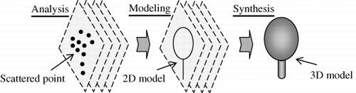
In principle, the premise necessitated for supporting the application of AMS (mainly for its first step of ‘analysis’) can be easily satisfied by MLS. That is, the capacity of marking scan profile indices is possessed by most MLS systems. Theoretically, this auto-marking facilitates using a block-by-block routine for sequentially processing and even on-line processing MLS data of large volumes. Next, the kernel procedure of exercising AMS is to geometrically model 2D scattered points (GM2P) in each ‘isolated’ scan profile. When GM2P is applied, the shapes in the scan profiles still represented by relatively considerable echoes can then be characterized by simple geometric primitives. This can maintain the efficiency of MLS data processing, even though the data volume keeps growing as a result of the vehicle moving. GM2P can also provide explicit morphological units for the reconstruction of the final 3D models. However, this does not mean that geometrically modeling 2D scattered points is an easy task, because diverse shapes may be encountered. Hence, a review of the GM2P algorithms under the AMS schematic frame (referred to as the AMS-GM2P schematic frame hereafter, or AMS-GM2P for short) will be implicative for enhancing MLS-based geometrically modeling objects.
2. Review premise
2.1. Fields
With the highest relevance to MLS data processing, three typical research fields – remote sensing (RS) based on the general sense of light detection and ranging (Lidar), robot perception (RP) and pattern recognition (PR) – are included in the literature review. Relevant studies have been carried out in the PR field for quite some time, whereas studies in the RP and RS fields date back 15 and 10 years, respectively.
2.1.1. Lidar-based remote sensing
Apart from MLS, the Lidar-based remote sensing community also includes satellite-based laser scanning (Duncanson, Niemann, and Wulder Citation2010), airborne laser scanning (ALS) (Wulder et al. Citation2007) and static terrestrial laser scanning (TLS) (Lovell et al. Citation2011). In fact, the AMS schematic frame stressed in this study has already been noted and attempted in the ALS and TLS branches. For example, airborne Lidar with the inherent function of scan profiling has been tried out in connection with forest canopy inventories (Nelson, Parker, and Hom Citation2003). ALS without this function has also been used in this way, and it has been implemented by artificially extracting scan profiles from its data (Sithole and Vosselman Citation2006). As regards TLS, the strategy of layering point clouds, i.e. a variant mode of GM2P, has been employed to locate tree stem positions (Lovell et al. Citation2011).
2.1.2. Robot perception
MLS systems can be intuitively regarded as the enhanced versions of robot sensory modules. In some cases, it is even hard to distinguish between robot Lidar and MLS in terms of system configuration (Yuan, Zhao, and Zhang Citation2010). Thus, some methods developed for robot perception of its environments are also valid for MLS data processing, and vice versa. For example, aerospace explorations based on robots, e.g. Lunar rovers with laser rangefinder (Krotkov et al. Citation1999) and Mars rovers with teleoperator manoeuvre assistance (Farahani Citation2007), have often been tried out with MLS-based information extractions in field trials. This rule works for the GM2P algorithms as well. Moreover, the GM2P scheme has also been implemented in the field of robot perception by means of hardware settings, since many of RP-purposed laser systems are simply configured with 2D laser rangefinders for improved efficiency (Forsberg, Larsson, and Wernersson Citation1995; Adams et al. Citation2008). In other words, RP scanners each time focus only on the horizontal scan profiles of the surroundings, and many algorithms rooted in robot scans substantially belong to the GM2P schematic frame.
2.1.3. Pattern recognition
In a broader sense, the GM2P algorithms have long been exploited in pattern recognition. After all, the necessity often arises for recognizing objects represented by 2D scattered points, even involving images with targets characterized by sparse pixels. Pattern recognition has also offered a higher-level theoretical description of this kind of problems. According to Sagerer and Niemann (Citation1997), a segmented object can be defined by its parts and their attributes and relations. The parts are the main results of decomposing an object into simpler constituents (parts here are the 2D geometrical models in the MLS scan profiles). The attributes describe some physical or geometrical properties of the parts. The relations are not attached to the parts, but describe their geometrical configurations. Hence, the segmentation of the object into parts is of key importance in context understanding. Studies about parts, attributes and relations have been carried out in many PR-related application fields, such as computer vision (Jiang and Bunke Citation1994), machine intelligence (Hoover et al. Citation1996), pattern modeling (Verbeek, Vlassis, and Kröse Citation2002), computer-aided design (Wu et al. Citation2004), and diagnostic medical imaging (Ecabert et al. Citation2008). A summary of the existing GM2P algorithms in the pan field of pattern recognition can offer theoretical guidance towards developing effective techniques for MLS-based object representation.
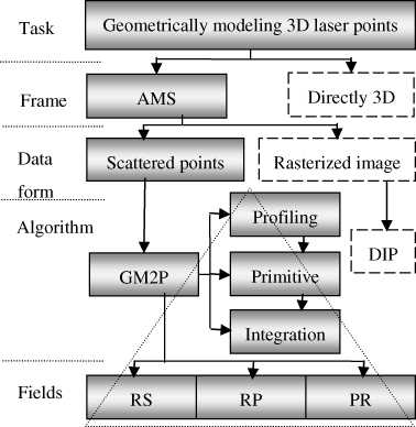
2.2. Outline
After the most relevant fields have been determined, the basic outline of this review was designed as manifested in . For the ultimate goal of developing efficient methods for geometrically modeling 3D scattered points, particularly with MLS data characteristics taken into account, two schematic frames can be adopted – AMS and directly modeling 3D points. AMS was the focus in this study. Next, the AMS-schemed methods can be divided into two major groups according to data forms – scattered points and rastered images. Actually, rasterized imagery is also a good data form for the purpose of geometrical modeling, because numerous mature methods in digital image processing (DIP) (Gonzalez and Woods Citation2007) can be directly used. However, the process of rasterization may introduce some omission errors into information extraction. Thus, the original scattered points were emphasized here. Finally, the related GM2P algorithms were further reviewed according to the common routines, i.e. definition of scan profiles, extraction of geometrical primitives, and integration of 2D models into 3D space. The review work will be deployed in the triangle with the three fields and three procedures considered crosswise.
3. Investigation of specific algorithms
The review of specific algorithms follows the paradigm of the AMS frame, and its ‘modeling’ procedure will be further divided into two explicit steps – segmentation of scattered points in each scan profile and geometrically modeling 2D scattered points.
3.1. Definition of scan profiles
3.1.1. Inherent scan profiles
In general, inherent scan profiles are directly provided by mapping modules such as MLS systems in urban surveys (Lin and Hyyppä Citation2011) and 2D range finders in robot navigation (Borges and Aldon Citation2004). With support from hardware settings, the definition of scan profiles can be easily fulfilled in this scenario. However, the point needing to be stressed here is that different configurations for the measurement of inherent scan profiles may result in different influences on the choice of the appropriate GM2P algorithms in the following steps. This is due to the resultant scan profiles possibly representing the object structures from different points of view. For example, the Riegl VMX-250 (Riegl Citation2010), Roamer (Kukko et al. Citation2007), and Sensei (Jaakkola et al. Citation2010) tend to observe the objects from different view angles. Hence, the patterns of morphological clues and geometric primitives are different for the same objects, and the related GM2P algorithms need to be adapted.
3.1.2. Artificially-defined transects
The other approach to defining scan profiles is based on artificially-defined transects. Although this plan requires more effort in setting up the rules for extracting scan profiles, it does turn out to be more flexible and robust in multiple situations. Typical cases using artificially-defined transects are known to have occurred in studies on forest growth investigations. Specifically, forest growth was derived based on two artificially-drawn scan profiles in airborne Lidar data, which was actually mapped in the spiral-scanning mode (Yu et al. Citation2006). Another case was one where gridding of ALS scattered points by interpolation was followed by the scan profiles being manually defined for bridge detection (Sithole and Vosselman Citation2006). There were also some efforts involving the proposed concept of profiling Lidar (Wulder et al. Citation2007), wherein ‘profiling’ was defined in accordance with its function rather than its configuration. In other words, this ‘profiling’ was still artificially defined by extracting ground elevation profiles with a filtering window according to the flight transects.
3.2. Segmentation of scattered points in each scan profile
After the definition of scan profiles, the segmentation of 2D scattered points in each scan profile needs to be conducted as a preparatory step for the AMS procedure of ‘modeling’. The specific operation is to partition the 2D scattered points in each scan profile into homogeneous subsets, each of which corresponds to an explicit morphology. The resultant point subsets can facilitate extracting the embedded geometric primitives. The basic principles of segmentation here can refer to the previous works aimed at range images. However, it should be noted that the scan profiles containing 2D scattered points are different from range images in data form. Apart from the relative locations, the points in range images have other attributes such as range or echo intensity from which the basic criteria for segmentation have been derived: discontinuity and similarity. For the scan profiles discussed in the present study, similarity cannot be relied on since no other attributes are attached to its points. For example, segmentation based on watershed (Kwak et al. Citation2007) and edge detection (Senthilkumaran and Rajesh Citation2009), depending on the criterion of point property gradients, cannot be applied directly in this case. Hence, the homogeneity criteria for segmentation of the scan profiles here can only assume the discontinuity of the scattered points (namely, the distances between the scattered points) in implicit forms (e.g. continuity as a local criterion) or in parametric forms (e.g. an algebraic equation as a global criterion), as summarized by Gächter, Nguyen, and Siegwart (Citation2006). Correspondingly, the methods available for segmentation of 2D scattered points are divided into two dominant schematic categories – primitive-independent and primitive-dependent – in terms of their relevance to the presumed geometrical primitives.
3.2.1. Primitive-independent
The algorithms of primitive-independent schematics () can segment 2D scattered points without struggling for the potential geometrical primitives. Theoretically, the target points can be divided into multi-groups only based on the distances between them.
Table 1. Summary of the algorithms of primitive-independent schematics for segmentation.
3.2.2. Primitive-dependent
The algorithms of primitive-dependent segmentation schematics () are often mixed with the following procedure of exerting GM2P. Particularly for iterative methods, it is often hard to set apart their implementations of segmentation and modeling. Thus, the segmentation methods of this kind here are only listed with simple descriptions, since a lot of specific cases in the next subsection still involve segmentation schematics such as region growing and split-and-merge.
Table 2. Summary of the algorithms of primitive-dependent schematics for segmentation.
3.3. Geometrically modeling 2D scattered points
Geometrically modeling 2D scattered points here is aimed at two common types of geometric primitives – line and curve. The latter also covers closed circles. The following reviews are divided according to these two primitives, respectively.
3.3.1. Geometrical primitive - line
For line-related point groups after primitive-independent segmentation, linear regression based on least-square fitting (Leon Citation2009) is the fundamental routine for acquiring their explicit line functions. However, for MLS mapping, simple linear regression is not enough, since various technical restrictions may be encountered, e.g. point groups with inconsistently-defined outliers or diverse objects with different requirements in data processing. In fact, many potential methods for tackling these special restrictions have been proposed in the referenced fields. For example, the total-least-squares algorithm (Forsyth and Ponce Citation2003) was assumed to compute the line parameters of a line and the covariance matrix of its inlier set. This technique can overcome the well-known bias issue of the least-squares method, which tends to put more weight on noisy and outlying points. Its equation details can refer to (Arras and Siegwart Citation1997), where another key idea inspired by the Hough Transform strategy is found. Specifically, the related algorithm first transforms the line extraction issue into a search problem in the model space (i.e. line parameter domain) and then executes the agglomerative hierarchical clustering (AHC) procedure (Agarwal, Alam, and Biswas Citation2010) to calculate the adjacent line segments. One drawback of this algorithm is that it is complex to implement. A weight linear fitting algorithm has also been proposed by Yuan, Zhao, and Zhang (Citation2010).
Principal component analysis (PCA) (Brigitte and Rouanet Citation2004) is also a classical plan for handling this challenge. Based on orthogonal transformation, this approach converts a set of observations of possibly correlated variables into a set of values of uncorrelated variables (i.e. principal components). The first principal component can be extracted to delineate the possible line, and this process can be illustrated by seeking the normal vectors in crown reconstructions (Kato et al. Citation2009). Essentially, line-oriented modeling is not restricted only to fitting the point groups with appropriate line equations. The process of geometrical modeling sometimes also comprises the procedure of line extraction. The representative algorithms dependent on this synthesized schematic frame are presented in . In addition, there are also many variant or enhanced versions of the above methods, but they are not listed here in details. For a more comprehensive comparison of the performance of the methods listed above, reference here is made to Nguyen et al. (Citation2005). The other details concerning their performances on line extraction in terms of environment sizes can also be found in Fernández et al. (Citation2010).
Table 3. Summary of the seven typical categories of line extraction algorithms.
3.3.2. Geometrical primitive - curve
The geometrical forms of curves, such as irregular curves, circles, ellipses and irregular close rings, can be fitted with specific parametric formulations. In this scenario, the highlights are to extract the embedded geometric models from the segmented point groups. Furthermore, the related formula coefficients need to be resolved.
For geometrically modeling circles and ellipses, common ellipse-fitting methods can work effectively. Several ellipse-fitting algorithms in the three review fields are listed in .
Table 4. Summary of the representative ellipse-fitting algorithms.
As regards irregular curves and irregular close rings, their geometrical models can be obtained by exploring their principal curves (Kégl et al. Citation2000). In practice, principal curves are often modelled as the integrations of line segments, but this does not mean that the methods aimed at geometrical primitives of lines are enough. The determination of the lengths of individual line segments and the total number of line segments is a tough problem, far more difficult than the pure process of line fitting. To address this issue, some vector quantification techniques have been used to find the approximations to principal curves, and several representative techniques are listed in . The k-segments algorithm has been introduced into MLS data processing for crown modeling in scan profiles (Lin and Hyyppä Citation2011). Indeed, the scheme of principal curves has supplied an effective and flexible way for dealing with the complex distributions of 2D scattered points.
Table 5. Summary of the representative algorithms for finding principal curves.
3.4. Integration of 2D models
The reports about integration of 2D geometrical models into full 3D models have proved to be few in number, since neither considerable GM2P algorithms have been developed nor have scan profiles been extensively exploited in previous studies. Some relevant works are listed as follows. The Scan Line Grouping (SGL) algorithm based on region growing has been proposed by Jiang and Bunke (Citation1994). Its primitives are straight line segments instead of individual points. This algorithm has gained some applications in the field of mobile robotics (e.g. Natonek Citation1998; Leger Citation1999) due to its simplicity and speed. Similar algorithms for planar surfaces have been developed by Haindl and Žid (Citation1997), and some have even been extended to curved surfaces (Jiang, Bunke, and Meier Citation2000; Khalifa, Moussa, and Kamel Citation2003). Apart from the integration of all parallel 2D models at the same time, the derived 2D models can also be iteratively fused in already existing 3D models. The algorithm of matching them can refer to Gruen and Akca (Citation2005), and this algorithm was based on least-square fitting.
4. Discussions
4.1. Potential application scenarios
The applicability of the summarized practices following the literature review and the derived clues helpful for developing new modeling methods keep strengthening, particularly with the range of MLS applications being continuously extended. This works specifically as follows. MLS systems based on sport utility vehicles (SUVs) can cope with most plain terrains. MLS systems carried by rail-based vehicles can measure dense tree vegetation along the tracks (Mettenleiter et al. Citation2008). Pedal-powered, and even human-propelled, tricycles equipped with laser scanners and positioning devices can survey streets, e.g. for the purpose of compiling Google Maps (Petrie Citation2010). A boat-based mobile mapping system (BoMMS) with a Faro LS880 scanner can be used for monitoring river-sides (Alho et al. Citation2009). A sled-borne MLS system has been used for mapping the thickness of snow (Kaasalainen et al. Citation2011). As regards dense forests or forests in mountainous areas, these hard-to-reach places have induced researchers to construct the Sensei system possessing the hybrid functions of terrestrial MLS and low-altitude ALS (Lin, Hyyppä, and Jaakkola Citation2011). With light-weight laser scanners becoming increasingly more available, backpack-styled MLS systems (Ellum Citation2001) have also been envisaged and prototyped by the research team of these authors.
The referred solution plans are also valid for more than the targeted scenario of MLS-based object representation. In fact, they can work in many other fields, ranging from computer-aided designing (Wu et al. Citation2004) to diagnostic medical imaging (Ecabert et al. Citation2008). From the perspective of generation of 3D points, the feasible sources include Lidar (Vosselman et al. Citation2004) and image matching often used in aerial photogrammetry (Leberl et al. Citation2010) and photography based on small unmanned aerial vehicles (UAVs) (Rosnell and Honkavaara Citation2012). As regards the latter technique, its present-day thriving study is referred to as a comeback of traditional stereo photogrammetry (Haala Citation2009). These all suggest that more and more means capable of yielding 3D points are available, and thus, the algorithms sought for geometrically modeling the resultant points have more applicable fields.
These varying application projects have resulted in a huge variety of AMS-GM2P-applicable scenarios. Specifically, the environments concerned comprise forests, plains, rivers, cities, etc. The referred objects include tree stems, snow, watercourses, buildings, etc. The outer shapes suitable in this context include cylinders, planes, curve surfaces, lines, etc. The possible geometrical primitives in 2D scan profiles contain points, lines, curves, ellipses, etc. In principle, the scenarios may cover different objects, different shapes, different scales, different reflectivity, different details, etc. All of these aspects need to be considered in the processes of GM2P. Namely, for each application case, a set of analysis-synthesis rules and a group of geometric models need to be pre-determined for object representation. Attempts at introducing the plan of object based image analysis (OBIA) into the Lidar field have also been made (Blaschke and Tomljenović Citation2012). Overall, the potential strategies for geometrically modeling 2D scattered points are theoretically scenario-oriented or object-oriented.
4.2. Pros and cons
While one of the potential strengths of the referred AMS-GM2P scheme frame is efficiency, no such exploitations and comparisons have been conducted as yet. Actually, it is difficult to evaluate the significance of the GM2P-schemed algorithms for object modeling in terms of efficiency. The reason lies in the fact that the ‘efficiency’ derived from the GM2P operations at the schematic level is beyond the traditional concept of data processing runtime at the algorithmic level. In a specific application case with similar-sized point clouds, the runtime of an algorithm under the AMS-GM2P frame may be worse than a comparative algorithm designed directly in a 3D sense.
However, overall efficiency extending from methodology development to model output may be better. The rationale is that the AMS frame supplies a flexible measure for manipulation of scattered points, and the GM2P scheme offers a high potential for predicting the semantic shapes of objects. For example, the strategy of sub-sampling is a potential technique. That is, 2D geometrical modeling can be deployed on every few scan profiles, and the spacing of sub-sampling is determined according to the relations between the sizes of objects and the frequencies of scan profiling. Based on this technique, a multi-level modeling scheme can be established. The possible locations of the targets are initially sought by sub-sampling, and the scan profiles comprising the targets are extracted. The extracted scan profiles are then geometrically modeled in more explicit 2D modes, and 3D models can be achieved by integration of these 2D models. By this means, the overall efficiency can be dramatically improved. Hence, the contribution of reviewing the GM2P-schemed algorithms is to offer an alternative way for modeling 3D scattered points, which is an efficient solution frame for the MLS data processing community as a whole.
The second aspect for discussion is the different configurations of laser scanning systems, since they may correspond to different 2D geometrical primitives for the same object and hence different integration patterns. For example, if the scan profiles are configured perpendicular to the terrain surface, the 2D geometric primitives of lighting poles and tree stems are line segments. Then, the related 3D models are acquired by circular clustering of parallel vertical line segments. If the scan profiles cross the terrain surface with a tilt angle, the related 2D geometric primitives are open curves. The same 3D models can then be achieved by parallel clustering of the resultant tilt open curves, after which they are fitted with a cylinder. It can be seen from this comparison that the relations of parts in modeling are dependent on both the shapes of objects and the sampling modes. As regards the explicit error models in geometric primitive extraction from 2D range scans, a large number of sophisticated error models have been discussed in (Diosi and Kleeman Citation2003).
The third aspect for discussion is nonparallel scan profiles, often occurring at the corners of roads where vehicles change routines. Special methods for the integration of 2D geometrical models need to deal with this disadvantageous situation. Nonetheless, such scenarios need to be first detected. This is implemented by comparing the normal vectors of two adjacent scan profiles. If there is an angle between them larger than the prescribed threshold, the scan profiles need to be marked out. Then, for the associated laser points, one possible robust solution is to segment the points related with the objects and then to geometrically model them directly in a 3D sense.
5. Conclusion
This review is aimed at resolving the implicative, but complicated, challenge of retrieving the geometrical models of the objects represented by 3D scattered points, which is explosively emphasized with the rapid development of MLS and stereo photogrammetry technology. In other words, this work is helpful in the endeavour to solve the type of technical bottlenecks currently encountered in the RS community. In addition to Lidar-based remote sensing in a 3D sense, robot perception and pattern recognition are also major associated domains. It was found that one alternative schematic in common is based on the AMS-GM2P methodological frame. The following literature review did supply a great number of algorithms that can be referenced for MLS-based object modeling. Overall, this review serves as more than a summary of the GM2P-schemed approaches for inspiring and enhancing the development of new algorithms under the same theoretical frame. Furthermore, this endeavor can open up a potential avenue for methodically improving the entire MLS field in terms of object representation in practical applications.
Acknowledgements
The authors are grateful for financial support from the Academy of Finland (Project ‘Towards improved characterization of map objects’).
References
- Adams, M., T. Fan, W. S. Wijesoma, and C. Sok. 2008. “Convergent Smoothing and Segmentation of Noisy Range Data in Multiscale Space.” IEEE Transactions on Robotics 24 (3): 746–753. doi:10.1109/TRO.2008.919294.
- Agarwal, P., M. A. Alam, and R. Biswas. 2010. “Analysing the Agglomerative Hierarchical Clustering Algorithm for Categorical Attributes.” International Journal of Innovation, Management and Technology 1 (2): 186–190. doi:10.7763/IJIMT.2010.V1.34.
- Alho, P., A. Kukko, H. Hyyppä, H. Kaartinen, J. Hyyppä, and A. Jaakkola. 2009. “Application of Boat-based Laser Scanning for River Survey.” Earth Surface Processes and Landforms 34 (13): 1831–1838. doi:10.1002/esp.1879.
- Arras, K. O., and R. Siegwart 1997. “Feature Extraction and Scene Interpretation for Map-based Navigation and Map Building.” In Proceeding SPIE ISAM'97, Pittsburgh, PA, October 14–17 (on CDROM).
- Aschoff, T., and H. Spiecker. 2004. “Algorithms for the Automatic Detection of Trees in Laser Scanner Data.” International Archives of Photogrammetry, RS and SIS 36 (Part 8/W2): 71–75. http://www.isprs.org/proceedings/XXXVI/8-W2/ASCHOFF.pdf..
- Barber, D., J. Mills, and S. Smith-Voysey. 2008. “Geometric Validation of a Ground-based Mobile Laser Scanning System.” ISPRS Journal of Photogrammetry and Remote Sensing 63 (1): 128–141. doi:10.1016/j.isprsjprs.2007.07.005.
- Bartneck, C., and M. J. Lyons. 2009. “Facial Expression Analysis, Modelling and Synthesis: Overcoming the Limitations of Artificial Intelligence with the Art of the Soluble.” In Handbook of Research on Synthetic Emotions and Sociable Robotics: New Applications in Affective Computing and Artificial Intelligence, edited by J. Vallverdu and D. Casacuberta, 33–53. Snippet: IGI Global.
- Biosca, J. M., and J. L. Lerma. 2008. “Unsupervised Robust Planar Segmentation of Terrestrial Laser Scanner Point Clouds Based on Fuzzy Clustering Methods.” ISPRS Journal of Photogrammetry and Remote Sensing 63 (1): 84–98. doi:10.1016/j.isprsjprs.2007.07.010.
- Bishop, C. M., M. Svensén, and C. K. Williams. 1998. “GTM: The Generative Topographic Mapping.” Neural Computation 10: 215–234. doi:10.1162/089976698300017953.
- Blaschke, T., and I. Tomljenović. 2012. “LidarScapes and OBIA.” In Proceedings of ASPRS 2012 Annual Conference, Sacramento, CA, March 19–23 (on CDROM).
- Borges, G. A., and M. J. Aldon. 2004. “Line Extraction in 2D Range Images for Mobile Robotics.” Journal of Intelligent and Robotic Systems 40 (3): 267–297. doi:10.1023/B:JINT.0000038945.55712.65.
- Brigitte, L. R., and H. Rouanet. 2004. Geometric Data Analysis: From Correspondence Analysis to Structured Data Analysis. Dordrecht: Kluwer.
- Décoret, X., F. Durand, F. Sillion, and J. Dorsey. 2003. “Billboard Clouds for Extreme Model Simplification.” ACM Transactions on Graphics 22 (3): 689–696. doi:10.1145/882262.882326.
- Dietmayer, K. C. J., J. Sparbert, and D. Streller 2001. “Model Based Object Classification and Object Tracking in Traffic Scenes from Range Images.” In Proceedings IEEE IV'01, Tokyo, May 13–16 (on CDROM).
- Diosi, A., and L. Kleeman 2003. “Uncertainty of Line Segments Extracted from Static SICK PLS Laser Scans.” In Proceedings ACRA'03, Brisbane, December 1–3 (on CDROM).
- Duda, R. O., and P. E. Hart. 1973. Pattern Classification and Scene Analysis. New York: John Wiley & Sons.
- Duncanson, L. I., K. O. Niemann, and M. A. Wulder. 2010. “Estimating Forest Canopy Height and Terrain Relief from GLAS Waveform Metrics.” Remote Sensing of Environment 114 (1): 138–154. doi:10.1016/j.rse.2009.08.018.
- Ecabert, O., J. Peters, H. Schramm, C. Lorenz, J. von Berg, M. J. Walker, M. Vembar, et al. 2008. “Automatic Model-based Segmentation of the Heart in CT Images.” IEEE Transactions on Medical Imaging 27 (9): 1189–1201. doi:10.1109/TMI.2008.918330.
- Ellum, C. 2001. “The Development of a Backpack Mobile Mapping System.” Master thesis, The University of Calgary, Canada.
- Farahani, H. S. 2007. “Teleoperator Turn Maneuver Assistance for a Mars Rover with Local Elevation Maps.” Master Thesis, University of Würzburg, Würzburg, Germany.
- Fernández, C., V. Moreno, B. Curto, and J. A. Vicente. 2010. “Clustering and Line Detection in Laser Range Measurements.” Robots and Autonomous Systems 58 (5): 720–726. doi:10.1016/j.robot.2009.10.008.
- Fischler, M., and R. Bolles. 1981. “Random Sample Consensus: A Paradigm for Model Fitting with Application to Image Analysis and Automated Cartography.” Communications of the ACM 24 (6): 381–395. doi:10.1145/358669.358692.
- Fitzgibbon, A., M. Pilu, and R. B. Fisher. 1999. “Direct Least Square Fitting of Ellipses.” IEEE Transactions on Pattern Analysis and Machine Intelligence 21 (5): 476–480. doi:10.1109/34.765658.
- Forsberg, J., U. Larsson, and A. Wernersson. 1995. “Mobile Robot Navigation Using the Range-weighted Hough Transform.” IEEE Robotics & Automation Magazine 2 (1): 18–26. doi:10.1109/100.388295.
- Forsyth, D. A., and J. Ponce. 2003. Computer Vision: A Modern Approach. Saddle River, NJ: Prentice Hall.
- Gächter, S., V. Nguyen, and R. Siegwart 2006. “Results on Range Image Segmentation for Service Robots.” In Proceedings ICVS'06, New York, January 5–7 (on CDROM).
- Gander, W., G. H. Golub, and R. Strebel. 1994. “Least-squares Fitting of Circles and Ellipses.” BIT 34 (4): 558–578. doi:10.1007/BF01934268.
- Gonzalez, R. C., and R. E. Woods 2007. Digital Image Processing. 3rd ed. Saddle River, NJ: Prentice Hall.
- Grady, L. 2006. “Random Walks for Image Segmentation.” IEEE Transactions on Pattern Analysis and Machine Intelligence 28 (11): 1768–1783. doi:10.1109/TPAMI.2006.233.
- Grady, L., and E. L. Schwartz. 2006. “Isoperimetric Graph Partitioning for Image Segmentation.” IEEE Transactions on Pattern Analysis and Machine Intelligence 28 (3): 469–475. doi:10.1109/TPAMI.2006.57.
- Graham, L. 2010. “Mobile Mapping Systems Overview.” Photogrammetric Engineering & Remote Sensing 76: 222–228. http://www.geocue.com/workflows/mar10_mms.pdf
- Gruen, A., and D. Akca. 2005. “Least Squares 3D Surface and Curve Matching.” ISPRS Journal of Photogrammetry and Remote Sensing 59 (3): 151–174. doi:10.1016/j.isprsjprs.2005.02.006.
- Haala, N. 2009. “Comeback of Digital Image Matching.” In Photogrammetric Week'09, 289–301, Heidelberg, Stuttgart, September 7–11.
- Haindl, M., and P. Žid. 1997. “Fast Segmentation of Range Images.” Lecture Notes in Computer Science 1310: 295–302. doi:10.1007/3-540-63507-6_214.
- Hinks, T., H. Carr, and D. Laefer. 2009. “Flight Optimization Algorithms for Aerial LiDAR Capture for Urban Infrastructure Model Generation.” Journal of Computing in Civil Engineering 23 (6): 330–339. doi:10.1061/(ASCE)0887-3801(2009)23:6(330).
- Hoover, A., G. Jean-Baptiste, X. Jiang, P. J. Flynn, H. Bunke, D. B. Goldgof, K. Bowyer, D. W. Eggert, A. Fitzgibbon, and R. B. Fisher. 1996. “An Experimental Comparison of Range Image Segmentation Algorithms.” IEEE Transactions on Pattern Analysis and Machine Intelligence 18 (7): 673–689. doi:10.1109/34.506791.
- Horowitz, S. L., and T. Pavlidis. 1976. “Picture Segmentation by a Tree Traversal Algorithm.” Journal of the ACM 23 (2): 368–388. doi:10.1145/321941.321956.
- Hyyppä, J., O. Kelle, M. Lehikoinen, and M. Inkinen. 2001. “A Segmentation-based Method to Retrieve Stem Volume Estimates from 3-D Tree Height Models Produced by Laser Scanners.” IEEE Transactions on Geoscience and Remote Sensing 39 (5): 969–975. doi:10.1109/36.921414.
- Jaakkola, A., J. Hyyppä, H. Hyyppä, and A. Kukko. 2008. “Retrieval Algorithms for Road Surface Modelling Using Laser-based Mobile Mapping.” Sensors 8 (9): 5238–5249. doi:10.3390/s8095238.
- Jaakkola, A., J. Hyyppä, A. Kukko, X. Yu, M. Kaartinen, M. Lehtomäki, Y. Lin. 2010. “A Low-cost Multi-sensoral Mobile Mapping System and its Feasibility for Tree Measurements.” ISPRS Journal of Photogrammetry and Remote Sensing 65 (6): 514–522. doi:10.1016/j.isprsjprs.2010.08.002.
- Jiang, X., and H. Bunke. 1994. “Fast Segmentation of Range Images into Planar Regions by Scan Line Grouping.” Machine Vision and Applications 7 (2): 115–122. doi:10.1007/BF01215806.
- Jiang, X., H. Bunke, and U. Meier. 2000. “High-level Feature Based Range Image Segmentation.” Image and Vision Computing 18 (10): 817–822. doi:10.1016/S0262-8856(99)00049-9.
- Kaasalainen, S., H. Kaartinen, A. Kukko, K. Anttila, and A. Krooks. 2011. “Brief Communication “Application of Mobile Laser Scanning in Snow Cover Profiling”.” The Cryosphere 5 (1): 135–138. doi:10.5194/tc-5-135-2011.
- Kato, A., L. M. Moskal, P. Schiess, M. E. Swanson, D. Calhoun, and W. Stuetzle. 2009. “Capturing Tree Crown Formation through Implicit Surface Reconstruction Using Airborne LIDAR Data.” Remote Sensing of Environment 113 (6): 1148–1162. doi:10.1016/j.rse.2009.02.010.
- Kégl, B., A. Krzyzak, T. Linder, and K. Zeger. 2000. “Learning and Design of Principal Curves.” IEEE Transactions on Pattern Analysis and Machine Intelligence 22 (3): 281–297. doi:10.1109/34.841759.
- Kenmochi, Y., L. Buzer, A. Sugimoto, and I. Shimizu. 2008. “Discrete Plane Segmentation and Estimation from a Point Cloud Using Local Geometric Patterns.” International Journal of Automation and Computing 5 (3): 246–256. doi:10.1007/s11633-008-0246-1.
- Khalifa, I., M. Moussa, and M. Kamel. 2003. “Range Image Segmentation Using Local Approximation of Scan Lines with Application to CAD Model Acquisition.” Machine Vision and Applications 13 (5,6): 263–274. doi:10.1007/s00138-002-0083-0.
- Kohonen, T. 1995. Self-organizing Maps. Berlin: Springer.
- Krotkov, E., M. Hebert, L. Henriksen, P. Levin, M. Manimone, R. Simmons, and J. Teza. 1999. “Evolution of a Prototype Lunar Rover: Addition of Laser-based Hazard Detection, and Results from Field Trials in Lunar Analog Terrain.” Autonomous Robots 7 (2): 119–130. doi:10.1023/A:1008926000060.
- Kukko, A., C. O. Andrei, V. M. Salminen, H. Kaartinen, Y. Chen, P. Rönnholm, H. Hyppä, et al. 2007. “Road Environment Mapping System of the Finnish Geodetic Institute – FGI Roamer.” International Archives of Photogrammetry, RS and SIS 36 (Part 3/W52): 241–247. http://www.isprs.org/proceedings/XXXVI/3-W52/final_papers/Kukko_2007b.pdf
- Kwak, D.-A., W.-K. Lee, J.-H. Lee, G. S. Biging, and P. Gong. 2007. “Detection of Individual Trees and Estimation of Tree Height Using LiDAR Data.” Journal of Forest Research 12 (6): 425–434. doi:10.1007/s10310-007-0041-9.
- Leberl, F., A. Irschara, T. Pock, P. Meixner, M. Gruber, S. Scholz, and A. Wiechert. 2010. “Point Clouds: Lidar versus 3D Vision.” Photogrammetric Engineering & Remote Sensing 76: 1123–1134. http://www.cis.rit.edu/~cnspci/references/dip/urban_extraction/leberl2010.pdf
- Leger, P.C. 1999. Fast Planar Segmentation of Range Data for Mobile Robots. United States Patent, No. 5978504.
- Lehtomäki, M., A. Jaakkola, J. Hyyppä, A. Kuukko, and H. Kaartinen. 2010. “Detection of Vertical Pole-like Objects in a Road Environment Using Vehicle-based Laser Scanning Data.” Remote Sensing 2: 641–664. doi:10.3390/rs2030641.
- Leon, S. J. 2009. Linear Algebra with Applications. 8th ed. New Jersey: Prentice Hall.
- Lin, Y., and J. Hyyppä. 2010. “Geometry and Intensity Based Culvert Detection in Mobile Laser Scanning Point Clouds.” Journal of Applied Remote Sensing 4: Article Number: 043553. doi:10.1117/1.3518442.
- Lin, Y., and J. Hyyppä. 2011. “k-Segments-based Geometric Modelling of VLS Scan Lines.” IEEE Geoscience and Remote Sensing Letters 8 (1): 93–97. doi:10.1109/LGRS.2010.2051940.
- Lin, Y., J. Hyyppä, and A. Jaakkola. 2011. “Mini-UAV-borne LiDAR for Fine-scale Mapping.” IEEE Geoscience and Remote Sensing Letters 8 (3): 426–430. doi:10.1109/LGRS.2010.2079913.
- Lovell, J. L., D. L. B. Jupp, G. J. Newnham, and D. S. Culvenor. 2011. “Measuring Tree Stem Diameters Using Intensity Profiles from Ground-based Scanning LiDAR from a Fixed Viewpoint.” ISPRS Journal of Photogrammetry and Remote Sensing 66 (1): 46–55. doi:10.1016/j.isprsjprs.2010.08.006.
- Maas, H.-G., and G. Vosselman. 1999. “Two Algorithms for Extracting Building Models from Raw Laser Altimetry Data.” ISPRS Journal of Photogrammetry and Remote Sensing 54 (2,3): 153–163. doi:10.1016/S0924-2716(99)00004-0.
- Mettenleiter, M., N. Obertreiber, F. Härtl, F. Ehm, J. Baur, and C. Fröhlich. 2008. “3D Laser Scanner as Part of Kinematic Measurement Systems.” In Proceedings 1st MCG, edited by H. Ingensand, and W. Stempfhuber, ETH: Zurich, June 24–26 (on CDROM).
- Morsdorf, F., E. Meier, B. Kötz, K. I. Itten, M. Dobbertin, and B. Allgöwer. 2004. “LiDAR-based Geometric Reconstruction of Boreal Type Forest Stands at Single Tree Level for Forest and Wildland Fire Management.” Remote Sensing of Environment 92 (3): 353–362. doi:10.1016/j.rse.2004.05.013.
- Natonek, E. 1998. “Fast Range Image Segmentation for Servicing Robots.” In Proceedings IEEE ICRA'98, 406–411, Leuven, May 16–20.
- Nebiker, S., S. Bleisch, and M. Christen. 2010. “Rich Point Clouds in Virtual Globes – A New Paradigm in City Modeling? Computers, Environment and Urban Systems 34 (6): 508–517. doi:10.1016/j.compenvurbsys.2010.05.002.
- Nelson, R., G. Parker, and M. Hom. 2003. “A portable Airborne Laser System for Forest Inventory.” Photogrammetric Engineering & Remote Sensing 69: 267–273. http://www.asprs.org/a/publications/pers/2003journal/march/2003_mar_267-273.pdf
- Nguyen, V., A. Martinelli, N. Tomatis, and R. Siegwart 2005. “A Comparison of Line Extraction Algorithms Using 2D Laser Rangefinder for Indoor Mobile Robotics.” In Proceedings IEEE IRS 2005, 1929–1934. Edmonton, August 2–8.
- Ohlander, R., K. Price, and D. R. Reddy. 1978. “Picture Segmentation Using a Recursive Region Splitting Method.” Computer Graphics and Image Processing 8 (3): 313–333. doi:10.1016/0146-664X(78)90060-6.
- Pavlidis, T., and S. L. Horowitz. 1974. “Segmentation of Plane Curves.” IEEE Transactions on Computers C 23 (8): 860–870. doi:10.1109/T-C.1974.224041.
- Petrie, G. 2010. “An Introduction to the Technology – Mobile Mapping Systems.” Geoinformatics (1,2): 32–43. http://web2.ges.gla.ac.uk/~gpetrie/Petrie_Mobile_Mapping_Systems_Jan-Feb_2010.pdf
- Pfister, S. T., S. I. Roumeliotis, and J. W. Burdick 2003. “Weighted Line Fitting Algorithms for Mobile Robot Map Building and Efficient Data Representation.” In Proceedings ICRA'03, Taipei, September 14–19 (on CDROM).
- Pitas, I. 2000. Digital Image Processing Algorithms and Applications. New York: John Wiley & Sons.
- Premebida, C., and U. Nunes 2005. “Segmentation and Geometric Primitives Extraction from 2D Laser Range Data for Mobile Robot Applications.” In Robótica'05, Coimbra, April 29–May 1, 17–25.
- Pu, S., M. Rutzinger, G. Vosselman, and S. O. Elberink. 2011. “Recognizing Basic Structures from Mobile Laser Scanning Data for Road Inventory Studies.” ISPRS Journal of Photogrammetry and Remote Sensing 66 (6): S28–S39. doi:10.1016/j.isprsjprs.2011.08.006.
- Riegl. 2010. Riegl VMX-250 Datasheet. Accessed August 8. http://www.riegl.com/nc/products/mobile-scanning/produktdetail/product/scannersystem/6/
- Rosnell, T., and E. Honkavaara. 2012. “Point Cloud Generation from Aerial Image Data Acquired by a Quadrocopter Type Micro Unmanned Aerial Vehicle and a Digital Still Camera.” Sensors 12 (12): 453–480. doi:10.3390/s120100453.
- Sagerer, G., and H. Niemann. 1997. Semantic Networks for Understanding Scenes (p. 512). New York: Plenum.
- Santos, S., J. E. Faria, F. Soares, R. Araújo, and U. Nunes 2003. “Tracking of Multi-obstacles with Laser Range Data for Autonomous Vehicles.” In Robotica'03, Lisbon, May 8–11, 59–65.
- Schnabel, R., R. Wahl, and R. Klein. 2007. “Efficient RANSAC for Point-cloud Shape Detection.” Computer Graphics Forum 26 (2): 214–226. doi:10.1111/j.1467-8659.2007.01016.x.
- Senthilkumaran, N., and R. Rajesh. 2009. “Edge Detection Techniques for Image Segmentation – A Survey of Soft Computing Approaches.” International Journal of Recent Trends in Engineering 1 (2): 250–254. http://www.academypublisher.com/ijrte/vol01/no02/ijrte0102250254.pdf
- Shapiro, L. G., and G. C. Stockman. 2001. Computer Vision. New Jersey: Prentice-Hall.
- Shi, J. B., and J. Malik. 2000. “Normalized Cuts and Image Segmentation.” IEEE Transactions on Pattern Analysis and Machine Intelligence 22 (8): 888–905. doi:10.1109/34.868688.
- Siadat, A., A. Kaske, S. Klausmann, M. Dufaut, and R. Husson. 1997. “An Optimized Segmentation Method for a 2d Laser Rangefinder to Mobile Robot Navigation.” In Proceedings 3rd ICICA, 153–158, Annecy, June 9–11.
- Sithole, G., and G. Vosselman. 2006. “Bridge Detection in Airborne Laser Scanner Data.” ISPRS Journal of Photogrammetry and Remote Sensing 61 (1): 33–46. doi:10.1016/j.isprsjprs.2006.07.004.
- Starly, B., A. Lau, W. Sun, W. Lau, and T. Bradbury. 2005. “Direct Slicing of STEP Based NURBS Models for Layered Manufacturing.” Computer-Aided Design 37 (4): 387–397. doi:10.1016/j.cad.2004.06.014.
- Tolso, R., and A. Fusiello. 2008. “Robust Multiple Structures Estimation with J-linkage.” Lecture Notes in Computer Science 5302: 537–547. doi:10.1007/978-3-540-88682-2_41.
- Vandorpe, J., H. V. Brussel, and H. Xu 1996. “Exact Dynamic Map Building for a Mobile Robot Using Geometrical Primitives Produced by a 2D Range Finder.” In Proceedings IEEE ICRA'96, 901–908, Minneapolis, Minnesota, April 22–28.
- Verbeek, J. J., N. Vlassis, and B. Kröse. 2002. “A k-segments Algorithm for Finding Principal Curves.” Pattern Recognition Letters 23 (8): 1009–1017. doi:10.1016/S0167-8655(02)00032-6.
- Verbeek, J. J., N. Vlassis, and B. Kröse. 2006. “A Soft k-segments Algorithm for Principal Curves.” Lecture Notes in Computer Science 2130: 450–456. doi:10.1007/3-540-44668-0_63.
- Vosselman, G., B. G. H. Gorte, G. Sithole, and T. Rabbani. 2004. “Recognising Structure in Laser Scanner Point Clouds.” International Archives of Photogrammetry, RS and SIS 36 (Part 8/W2): 33–38. http://www.isprs.org/proceedings/XXXVI/8-W2/VOSSELMAN.pdf
- Wu, Z., and R. Leahy. 1993. “An Optimal Graph Theoretic Approach to Data Clustering: Theory and its Application to Image Segmentation.” IEEE Transactions on Pattern Analysis and Machine Intelligence 15 (11): 1101–1113. doi:10.1109/34.244673.
- Wu, Y., Y. Wong, H. Loh, and Y. Zhang. 2004. “Modelling Cloud Data Using an Adaptive Slicing Approach.” Computer-Aided Design 36: 231–240. doi:10.1016/S0010-4485(03)00097-6.
- Wulder, M. A., T. Han, J. C. White, T. Sweda, and H. Tsuzuki. 2007. “Integrating Profiling LiDAR with Landsat Data for Regional Boreal Forest Canopy Attribute Estimation and Change Characterization.” Remote Sensing of Environment 110: 123–137. doi:10.1016/j.rse.2007.02.002.
- Xavier, J., M. Pacheco, D. Castro, A. Ruano, and U. Nunes 2005. “Fast Line, Arc/Circle and Leg Detection from Laser Scan Data in a Player Driver.” In Proceedings IEEE ICRA'05, 3930–3935, Barcelona, April 18–22.
- Yu, X., J. Hyyppä, A. Kukko, M. Maltamo, and H. Kaartinen. 2006. “Change Detection Techniques for Canopy Height Growth Measurements using Airborne Laser Scanner Data.” Photogrammetric Engineering & Remote Sensing 72 (12): 1339–1348. http://www.asprs.org/a/publications/pers/2006journal/december/2006_dec_1339-1348.pdf
- Yuan, X., C. X. Zhao, and H. F. Zhang. 2010. “Road Detection and Corner Extraction Using High Definition LiDAR.” Information Technology Journal 9 (5): 1022–1030. doi:10.3923/itj.2010.1022.1030.
- Zahn, C. T. 1971. “Graph-theoretical Methods for Detecting and Describing Gestalt Clusters.” IEEE Transactions on ComputersC-20 (1): 68–86. doi:10.1109/T-C.1971.223083.
- Zampa, F., and D. Conforti. 2009. “Mapping with Mobile LiDAR.” GIM International 23: 35–37. http://www.gim-international.com/issues/articles/id1306-Mapping_with_Mobile_Lidar.html
- Zhang, J. P., and D. W. Chen. 2006. “Constraint k-segment Principal Curves.” In ICIC 2006, LNCS, edited by D.S. Huang, K. Li, and G.W. Irwin, 345–350. Kunming, China, August 16–19, 4113.
- Zhao, H., and R. Shibasaki. 2003. “A Vehicle-borne Urban 3-D Acquisition System Using Single-row Laser Range Scanners.” IEEE Transactions on Systems, Man, and Cybernetics, Part B: Cybernetics 33 (4): 658–666. doi:10.1109/TSMCB.2003.814280.
- Zuliani, M., C. S. Kenney, and B. S. Manjunath 2005. “The MultiRANSAC Algorithm and its Application to Detect Planar Hymnographies.” In Proceedings IEEE ICIP, Genoa, September 11–14 (on CDROM).