
ABSTRACT
An Augmented virtual environment (AVE) is concerned with the fusion of real-time video with 3D models or scenes so as to augment the virtual environment. In this paper, a new approach to establish an AVE with a wide field of view is proposed, including real-time video projection, multiple video texture fusion and 3D visualization of moving objects. A new diagonally weighted algorithm is proposed to smooth the apparent gaps within the overlapping area between the two adjacent videos. A visualization method for the location and trajectory of a moving virtual object is proposed to display the moving object and its trajectory in the 3D virtual environment. The experimental results showed that the proposed set of algorithms are able to fuse multiple real-time videos with 3D models efficiently, and the experiment runs a 3D scene containing two million triangles and six real-time videos at around 55 frames per second on a laptop with 1GB of graphics card memory. In addition, a realistic AVE with a wide field of view was created based on the Digital Earth Science Platform by fusing three videos with a complex indoor virtual scene, visualizing a moving object and drawing its trajectory in the real time.
1. Introduction
After more than eighteen years of development of Digital Earth (Gore Citation1998), many kinds of Digital Earth Systems have been created and applied in scientific simulation, global change, resource exploration and protection, and disaster monitoring and prevention (Guo Citation2009). Although the data used in 3D virtual environments mostly come from our real world, they all represent the past, static scenes when they were acquired, and are thus unable to meet the requirements of real-time applications. As a proper three-dimensional, visual way for human beings to cognize Earth, a Digital Earth System should parse, visualize and analyse location-related, highly time-sensitive data, and merge the real-time data from the real world to the virtual scene so that one could, for example, easily know what is happening outside in an emergency evacuation scenario. The development of a next-generation Digital Earth also involves real-time data acquired by sensor networks to augment virtual environments (De Longueville et al. Citation2010; Goodchild et al. Citation2012).
An Augmented Virtual Environment (AVE) is defined as a fusion of dynamic imagery with 3D models (Neumann et al. Citation2003). In a broad sense, an AVE can be described as fusing some reality-related, real-time, dynamic information with 3D models or virtual scenes, augmenting the dynamic, instantaneous 3D virtual environment. Many real-time and spatiotemporal dynamic data such as video, audio, temperature data and Radio Frequency Identification signals are suitable for fusion with virtual environments, among which videos are the most commonly available and location-related data. Videos carry content-rich information and they can provide dynamic scenes of the real world at present or in the past. This makes them significant, useful data for augmenting a 3D virtual scene by showing the videos in the 3D scene or fusing the video images with 3D models so that we can access both the virtual scene and the real world expediently. With the development of video processing technology, such as object tracking (Yilmaz, Javed, and Shah Citation2006), the result of video processing can also be fused with the virtual scene, for example, the texture and 3D position of moving objects. Furthermore, as advanced video hardware keeps becoming available, it is possible to use high-resolution images and detailed information to build more realistic AVEs.
The research on AVEs is mostly concentrated in video surveillance. Neumann et al. (Citation2003) first presented the concept of AVEs and an AVE system was established by fusing dynamic imagery with 3D models to support information extraction and dynamic scene analysis for an improved understanding of the scene. Sebe et al. (Citation2003) introduced their technical extensions to an AVE system, in which the moving objects were detected and visualized as pseudo 3D elements. They provided an excellent way to help observers comprehend videos and images from arbitrary views of the 3D scene. However, the 3D models they used to fuse with videos were as simple as boxes and the texture distortions were not eliminated, resulting in distorted, incorrectly projected textures on the buildings and the ground. Although the moving objects were extracted as rectangles and placed in the scene, they were surrounded by redundant background pixels. GeoScopeAVS, a GIS-based system for augmented video surveillance (Milosavljević, Dimitrijević, and Rančić Citation2010), was developed to register geospatial data applicable to outdoor video surveillance systems consisting of several PTZ cameras. The alignment of camera views and 3D GIS can identify geospatial objects from the camera image and overlap the virtual scene with the real one. This system mainly aimed to retrieve information about viewed geospatial objects, but the fusion of videos with 3D models was not taken into consideration. The SkylineGlobe TerraExplorer produced by Skyline Software Systems, Inc. allows a video file to play either on a selected area of the terrain (Video On Terrain), or on a floating billboard (Video Billboard), but this function is too simple to meet various requirements. A 3D GIS integrated with a video surveillance system based on Skyline was presented (Huang, Han, and Chen Citation2011) to provide a visual 3D scene and some analysis functions for video surveillance. A multiple sparse camera-based free view video system prototype (Silva, Santos, and Morimoto Citation2011) was developed to observe real scenes in a 3D virtual environment from any desired viewpoints and the moving targets were rendered to view-dependent texture-mapped billboards. However, the virtual environment they augmented was composed of simple planes, so it was quite different from the real world and the depth information could not be considered as well. A fused system with 3D GIS and multiple videos (Ma, Zhao, and He Citation2012) was designed and implemented to project multiple videos to the ground to show real-time video, but neither the overlapping gap of the adjacent videos nor the depth information was considered. A 2D + 3D visualization method with dual-resolution design for surveillance systems (Chen et al. Citation2012) was proposed by integrating multiple camera views and a Google Earth satellite image with 3D building models. This system allows to view the videos from different angle at discretion to acquire immersive experience as monitoring in the virtual 3D space. Streaming location-based panorama videos were mixed with an AVE (Zhou et al. Citation2014) to create a global sense of multiple bubbles and observe the bubbles at any view. Although the panorama videos were not fused with the 3D models, it still can enhance users’ walk-through experiences in the experiment environment.
The 3D models fused with videos in most studies are set in a 3D GIS or Digital Earth system. Fusing real-time videos with the virtual scenes in a 3D GIS or Digital Earth system to establish an AVE can take full advantage of spatial localization and visualization of the 3D scene, and significantly extend the applications of video processing results. The 3D scene can organize many cameras from different places together and visualize the videos respectively according to the cameras’ coordinates. Compared with other integration of video and virtual reality such as video-capture virtual reality (Weiss et al. Citation2004; Yang, Chen, and Chang Jeng Citation2010) and panoramic video-based virtual environments (Liu et al. Citation2003; Macedonio et al. Citation2007), such an AVE can give more comprehensive spatial information of the scene regionally or globally and fully fuse the videos to the virtual environment synchronously on both image and knowledge level, thus it will have important significance for some time-critical applications of Digital Earth, such as 3D video surveillance, emergency response and management, public security issues, intelligent transportation, location and navigation service, urban planning and management. However, there are some problems in current studies. For example, the 3D models fused with videos are generally simple, and moving objects (people, cars) have not been handled separately in most studies.
In this paper a new approach to establishing an AVE is proposed by fusing multiple real-time videos with a complex indoor virtual scene. The approach includes real-time video projection, multiple video texture fusion and 3D visualization of a moving object. The data preparation is introduced in Section 2. A reverse projection culling and depth test algorithm developed for the study is applied to eliminate errors caused by the conventional projective texture mapping (Section 3.1). An original diagonally weighted algorithm is proposed to fuse the overlapping gaps between the two adjacent videos (Section 3.2). A moving virtual object location and trajectory visualization method is proposed to display the moving object individually and draw its trajectory along with the 3D object model in the virtual environment (Section 3.3). Section 4 presents the result of multi-videos fusion with 3D models and visualization of one moving object based on Digital Earth Science Platform (DESP), as well as the efficiency analysis. Finally, the conclusion and future improvements are elaborated in Section 5.
2. Data preparation
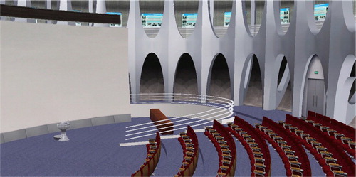
An ideal scene for establishing an AVE is a spacious, neat or open area, for example, a hall, a corridor, a square or a yard, where there are few clutters and coverings like trees or pot plants. As the real-time videos are captured from the real scene, the 3D models of the virtual scene, at least the structure of the 3D models should be as accurate as possible so that the videos and the 3D models can match well. Now many 3D modelling methods can meet the requirement, such as CAD-based interactive modelling, close-range photogrammetry (Luhmann et al. Citation2013), structure from motion (Agarwal et al. Citation2009; Cao and Snavely Citation2014), 3D laser scanning (Riveiro et al. Citation2011) and Oblique Aerial Photography (Remondino and Gerke Citation2015). In this paper the test site is the Virtual Reality Hall in the Institute of Remote Sensing and Digital Earth (RADI), Chinese Academy of Sciences (CAS). It is a round, drum-like building with a complex structure, whose outer wall is a curved surface supported by 30 evenly arrayed but irregularly shaped pillars. Combining CAD data and a close-range photogrammetric technique, the hall was digitized to a 3D model, as shown in .
Figure 1. Virtual scene of the Virtual Reality Hall. The white part on the left is a huge spherical screen wall. The pillars are in the top right of the figure and the outer wall is behind the pillars. The structure error of this model is around 10 cm.
The digital earth system used to display the 3D models is the Digital Earth Science Platform (Guo, Fan, and Wang Citation2009) or DESP, a large spatial information management and integrated analysis system, based on the concept of ‘next generation of Digital Earth’. The DESP is composed of several technology subsystems, including management and aggregation for massive spatial data, spatial information service and scientific data sharing, data-intensive analysis and high performance computing, and geographic simulation and visualization, and multiple application systems such as global change and nature disaster application system. When establishing an AVE, the DESP can provide a unified geospatial coordination to organize, analyse and visualize different kinds of data, such as the terrain, the remote sensing images, the 3D models, the surveillance cameras and the real-time videos. In this paper the 3D models were placed in the DESP by their geographical coordinates (latitude, longitude and height) so that a simple virtual environment of the Virtual Reality Hall was built to fuse with videos.
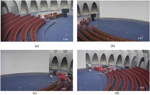
As the videos are fused with the 3D models directly, there is no need to worry about whether one video can match with another or not, and the number of videos is not strictly limited. The more the videos are, the more information can be acquired to augment the virtual scene. The position and the orientation of the surveillance camera will affect what kind of information that can be used: a top-view camera can get separate objects easily but it may not able to get the full textures of the objects; an oblique camera can get detailed textures but the object occlusion may arise. In order to cover most of the Virtual Reality Hall and create an AVE with a wide field of view, six fixed-hemisphere video cameras were installed around the pillars. Each camera has a resolution of 720p and captures videos from an oblique view. The video camera positions in the Virtual Reality Hall are shown as green points in . A sample of video images is illustrated in . The adjacent videos have some overlapping areas so that multiple videos can be merged into a wide-field scene together with 3D models.
Figure 2. Camera positions in the Virtual Reality Hall. The green points are the surveillance cameras. Each camera is installed at the junction of two pillars and captures videos from an oblique view.
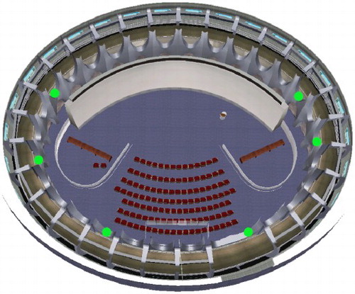
Figure 3. Screenshots of video data. (a) Camera 140; (b) Camera 143; (c) Camera 142; (d) Camera 141. The resolution of each video is 1280 × 720, and there are some overlapping areas between two adjacent videos, such as (a) and (b).
3. Methodology
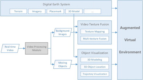
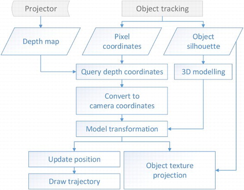
The major steps for creating an AVE by fusing real-time videos and 3D models in the Digital Earth system are shown in . The Video Processing Module preprocesses the videos and provides the essential data (background images, position and texture of moving objects, etc.) for creating an AVE by some common video processing methods, such as camera calibration, lens distortion correction, image smoothing, object extraction and tracking. The Video Texture Fusion Module maps the video textures onto the 3D models and fuses the overlapping video textures. The Object Visualization Module creates 3D models according to the moving object’s texture, and locates and updates the object model in real time. The Video Texture Fusion Module and Object Visualization Module cover the major algorithms for fusion of real-time videos and 3D models, so they will be introduced later in the paper. The Video Processing Module contains some commonly used methods thus they will not be elaborated on in detail here.
Figure 4. Flowchart for creating an AVE in the Digital Earth system.
3.1 Video texture mapping
Projective texture mapping is a mature method for generating texture coordinates automatically (Segal et al. Citation1992). It allows projecting a texture image or video images onto a 3D scene, as a projector projects a slide on a wall (Everitt Citation2001). It can obtain texture coordinates in projective space just by setting the view matrix and projection matrix. In order to project the video images onto the corresponding surface of the virtual scene, we need to setup a projector for each surveillance camera according to the camera parameters, such as the coordinates, orientation, FOV, video size in pixels. The camera positions (geographical coordinates) and orientations (heading, pitching, rolling) are readily available because the 3D models of the cameras have been loaded into the virtual scene of the DESP. An approximate calibration between a video frame and the 3D models can be done by setting the projector parameters manually according to these prior knowledges about the cameras. An accurate calibration can be calculated by some existing and reliable methods, for example, the single view camera calibration (Wang, You, and Neumann Citation2007).
However, a couple of issues should be noted when projective texture mapping is applied: reverse projection (Everitt Citation2001) and depth texture error. In this study, two modifications for projective texture mapping were applied: a reverse projection culling algorithm and a depth test algorithm based on OpenGL Shading Language (GLSL, Rost Citation2009). Although they are not advanced algorithms, they will still be introduced briefly in consideration of the integrity of the whole approach of establishing an AVE.
Reverse projection results from a reverse projection that appear behind the projector when the fourth component of texture coordinate (q) becomes negative. Thus a filter, for example, gl_TexCoord[i].q ≥ 0, can be applied to eliminate the reverse projection before querying texture coordinates in the GLSL fragment shader.
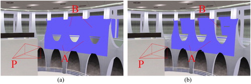
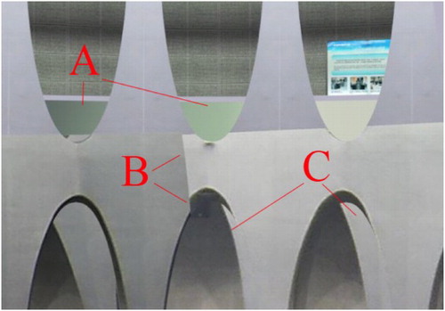
As the projective texture mapping method does not consider the depth information of the 3D scene when projecting an image or video, every model in the projector’s view will be rendered with projective textures, as if the projector could look through the models. As shown in (a), the surfaces behind the pillars (B) cannot be seen from the projector so they are not supposed to be rendered with blue (test image). Depth testing is a well-known and widely used method in 3D graphics, and the concept can also be introduced to fix the depth texture error of projective texture mapping. Setup a depth camera according to the projector’s parameters and capture a depth map of the 3D scene from the view of the projector. Then pass the depth map into the fragment shader to judge whether the current fragment of the model should remain its original colour or be rendered with the video texture. As shown in (b), the depth texture error (B) is eliminated after depth testing. The depth map does not need to be updated unless the video camera moves or zooms, and it will also be used in the Object Visualization Module. Although the depth information can also be obtained by stereovision or structure from motion, it is better to take the advantage of the accurate virtual scene to meet the demand of real-time processing and rendering.
Figure 5. Result before and after applying the depth test algorithm. P: the projector. A: the walls and pillars nearest to the projector. B: the surfaces behind the pillars.
3.2. Fusion of multiple video textures
3.2.1. Introduction and problem statement
When projecting multiple real-time videos onto 3D models simultaneously to establish a wide-field view AVE, there will be some obvious gaps in the overlapping area, which is similar with what happens in digital image mosaicking (Szeliski Citation2006). Fusion of multiple video textures is to fuse video images in a 3D virtual environment and require unique methods because it is much different with video stitching in computer vision or multi-texture fusion in 3D computer graphics. There are various difficulties to fuse multiple video textures, illustrated as follows.
Differences in texture coordinate systems make it hard to calculate the transforms between them and unify the coordinates in the overlapping area as well. Every texture in 3D computer graphics has its own coordinate system and the valid texture coordinates in every axis range in [0, 1]. Generally, multiple video textures have different positions, orientations and sizes, as shown in . Thus there is no unified coordinate system to connect different texture coordinate systems.
Various ordinal relations between video textures require different ways of computing the coordinates of the overlapping area. Taking (b) as an example, the texture in unit 2 will overlap the lower right corner of the texture in unit 1, while the lower left corner of the texture in unit 1 will overlap when it turns to the configuration in (e). Assuming that the area overlap ratio is m in transverse (s-axis) and that of vertical direction (t-axis) is n, and
, then the texture coordinates of the overlapping areas in can be represented in .
Difficulty of applying complex algorithms to GLSL shader. The 3D rendering pipeline deals with the scene vertex by vertex and fragment by fragment, which makes it difficult to obtain the coordinate and colour value of other fragments from the current processed fragment, not to mention to apply complex algorithms to the whole texture over and over again as digital image processing does.
Figure 6. Difference in texture coordinate systems. Two textures A and B have their own separate texture coordinate systems, and
.
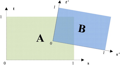
Figure 7. Ordinal relations of video textures.
Table 1. Texture coordinates of overlapping areas in .
Therefore, multiple video texture fusion algorithms should be simple to compute and highly efficient to implement so that they can eliminate the video texture gaps and meet the demand of real-time rendering as well. Since the directions and position relations of neighbouring projected video textures should be considered carefully, this paper proposes an efficient algorithm for fusing multiple video textures: the diagonally weighted algorithm.
3.2.2. Diagonally weighted algorithm
The diagonally weighted algorithm fuses neighbouring video textures along the diagonal direction in a GLSL fragment shader. The idea is similar to the gradated in-and-out blending algorithm in digital image mosaicking, but the diagonally weighted algorithm blends the overlapping video textures of adjacent texture units, fragment by fragment using GLSL. Taking or (c) as an example, the current texture is unit 2 which has overlapped the texture in unit 1, and the overlapping area is ABCD. Line EF is above and parallel to the diagonal line BD, and point P is on the EF. A local coordinate system is needed to unify the different texture coordinates in each unit, for example, take point B as the origin, as the x-axis and
as the y-axis. Assuming the coordinate of P in unit 2 is
and that in unit 1 is
, then the coordinate of P in the local coordinate system is
and that of point D is
, in which
is the maximum distance in the s-axis and
is the maximum distance in the t-axis. The slope and linear equation of BD can be described as:
(1)
(2) As EF is parallel to BD, we can get:
(3) So the distance of AF or m is:
(4)
Figure 8. Diagram of the diagonally weighted algorithm.
Because MP is parallel with AF, the coefficient of the current texture unit can be calculated based on the similar triangles approach when
(the point P is above the line BD):
(5)
Similarly, when (the point P’ is below the line BD) the coefficient can be calculated as
(6)
Once the coefficient is calculated out, the fused fragment colour after unit 2 () can be computed by
(7) where
is the fragment colour in unit 2, and
is the output fragment colour from unit 1. Then pass
into the next texture unit to fuse other overlapping video textures with the diagonally weighted algorithm.
The different expressions of the coefficient are calculated and enumerated according to different ordinal relations of video textures, as shown in Equation (8), which can be applied to a GLSL shader directly and help to omit some inference steps and finally improve the efficiency of the shader.(8) The simplified diagonally weighted algorithm is summarized as follows:
Initialization. Set a counter num to zero and the counter will record the number of the video textures that are projected onto the current fragment. Then enter into the first texture unit.
If the current texture unit is no more than the max texture unit, go to the next step; otherwise, end this algorithm.
Pre-processing. Apply the reverse projection culling and the depth test algorithm to make sure the videos are projected on the right place.
Judge if the current fragment has a valid video texture colour because the fragment shader is applied to all the fragments but not all the fragments are projected by video textures. If true, make the counter num plus one; otherwise, go to step (7).
If num ≥ 2, record the texture coordinates (s2, t2) in current unit and (s1, t1) in the last unit. Then calculate Smax and Tmax. Otherwise, go to step (7).
Calculate the coefficient by Equation (8), and fuse the fragment colour by Equation (7).
Pass the colour value into the next texture unit to fuse other overlapping video textures, then go to step (2).
The ordinal relations of video textures we used to deduce the algorithm are regular and specific: the video textures are not rotated and the texture coordinate systems are parallel to each other. However, the projected video textures actually will rotate and distort to a certain degree, thus the diagonally weighted algorithm should be checked to see if it is robust. As shown in and , the solid-line arrow (diagonal) points in the direction of weight changes and the dot-dash line (weight isoline) means the weight values on it are the same. Both figures give the isolines of 0.2, 0.4, 0.5, 0.6 and 0.8.
Figure 9. Weight isolines of regular relations between video textures.
shows that when the overlapping area is a regular rectangle, the diagonal is a straight line and on each side the weight isolines are straight, which means the weights’ change is uniformly linear along the diagonal direction. shows when the overlapping area is irregular, the diagonal is a curve and the weight isolines on each side are also curves, but they do not interrupt or leap, which means the changes in weight are non-linear but continuous, and the trend of the changes is similar to the diagonal curve. This result shows that the diagonally weighted algorithm can adapt to various relations of video textures and ensure the smooth transition of the texture colour values.
Figure 10. Weight isolines of irregular relations between video textures.
3.3. 3D Visualization of a moving object
Although the algorithms for mapping and fusing multiple video textures can visualize real-time videos in 3D environments and eliminate the obvious gaps in the overlapping area of adjacent video textures, they are circumscribed in the video background. When moving objects appear in the video, for example, people and cars, the projected moving objects will be stretched and attached to the models because they are not taken into consideration in the above algorithms. As shown in , if we view the projected moving object from the virtual projector (a), it looks normal as seen in the video, but it will be stretched and attached to the models when we look at it from a different view of the projector (b). Thus the moving object should be extracted from the video and visualized as an independent 3D model in the 3D scene. That is why before fusing multiple video textures we implemented the Video Processing Module, in which the moving object was extracted and represented as a silhouette with texture so that the complete shape and colour information of the moving object could be displayed, as shown in .
Figure 11. Stretched moving object. (a) Front view from the virtual projector and (b) oblique view.
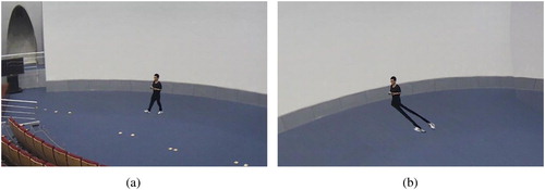
Figure 12. Examples of an object silhouette with texture. P: the bottom middle point of the silhouette.
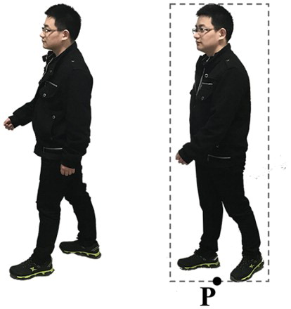
Considering that the video scenes are very simple (static surveillance cameras, single moving object) and the video processing method needs to meet the real-time requirement, the moving object was extracted by a series of simple and efficient algorithms including Gaussian smoothing, background modelling by Mixture Gauss Model (Stauffer and Grimson Citation2000), background subtraction, contour filling, dilation and erosion. But for more complex situations, for example, scene with shadow and multi-objects, some improved object tracking methods should be applied to get separated and intact object silhouettes. The example of an object silhouette with texture is shown in and the pixel coordinates of the bottom middle point (P) are recorded in the real time.
Given the information of the moving object (silhouette with texture, position in video image) and the 3D models in the Digital Earth system, the main contents of the proposed 3D visualization method for moving objects are:
3D modelling for moving objects. Make a 3D model to display the extracted object texture.
Object location and object texture projection. Compute the right 3D coordinates of the moving object model, place the object model into the 3D scene, project the texture of the object silhouette onto the object model by the projective texture mapping that is used in Section3.1, and update its position in real time.
Trajectory visualization. Draw the trajectory of the virtual moving object in real time.
3D modelling for moving objects means making a 3D model that can display the moving object in the virtual scene, for example, a virtual human model or an upright polygon model. A virtual human model needs to extract a lot of accurate information from videos, such as shape, height, gestures of moving object to make the model realistic. By comparison, a polygon model will be more convenient and practical, although it may cause projection failure in some extreme cases, for example, when the object is right under a zenith camera. Considering that the results of object tracking are generally two-dimensional images and position coordinates, the best way to 3D model a moving object is to build a rectangular polygon model on which the textured object silhouette is projected. Out of the object silhouette the polygon model is transparent, in which way there will be a textured object silhouette moving in the virtual scene after placing the polygon model in it.
Object location is to place the object model in a corresponding position in the 3D scene according to the object’s position in the video or the real world, and update its position in real time. It is a crucial step to link the 2D object image to the 3D virtual scene and truly realize 3D visualization of a moving object. Combining the object’s position information with the parameters of the virtual projector, the 3D coordinate of the moving object model in the virtual scene can be computed. But first, some assumptions should be given:
The virtual scene has high fidelity which means it has little difference with the real scene, including position, size, relative relationship, etc.
The moving object never hangs in the air and its bottom is always in contact with some object in the real scene, for example, the ground or floor.
During object tracking, the bottom of the moving object can be detected and extracted at all times.
Based on these assumptions this paper proposes an object location and trajectory visualization algorithm to place the object model and draw the trajectory in real time. It is described as:
Capture a depth map of the 3D scene from the virtual projector, which is the same as that of the depth test algorithm in Section 3.1.
Compute the 2D coordinates of the moving object in the video image. Record the pixel coordinates of the bottom middle point of the extracted object and normalize it to [0, 1] according to the video image size.
Query the depth coordinate of the bottom middle point from the depth map. Suppose that the normalized coordinate of the bottom middle point is (s, t), and the texture coordinate of the corresponding point in the depth map is
Build a rectangular polygon model for the moving object. For multiple moving objects, a polygon model should be built for every object because the coordinates of the objects are different from each other.
Transform the 3D moving object model to the Digital Earth system, and make the model upright to the ground and the normal vector points to the projector at all times, so that the object texture can be projected onto the object model:
Update the world coordinates of the object model and project the object texture onto the polygon model while the object is moving in the real time. Setup a callback method, pass the object’s pixel coordinates in the video frame into the method consistently and update the position of the object model according to Equation (9). The method to project the object texture is the same as that in Section 3.1.
Draw the trajectory in real time. Record the coordinates of the object model, connect them into a 3D line and draw it in the virtual scene while the object is moving. For the Digital Earth system, it is better to use geodetic coordinates (latitude, longitude and height) to create the 3D trajectory line and the geodetic coordinates can be converted from
The flowchart of object location and trajectory visualization is shown in .
Figure 13. Flowchart of object location and trajectory visualization in a 3D scene.
4. Results and discussion
A wide field of view AVE based on DESP was created by projecting multiple real-time videos onto the Virtual Reality Hall model, fusing multiple video textures together, tracking and visualizing the moving object in the virtual scene, and finally drawing the trajectory in the real time.
4.1. Video texture mapping and multiple video texture fusion
The proposed reverse projection culling algorithm, depth test algorithm and diagonally weighted algorithm are able to eliminate the reverse projection and depth texture error, and smooth the obvious video gaps within the overlapping area of the two adjacent video textures.
As shown in , when multiple videos are projected onto 3D models by the conventional projective texture mapping algorithm, the transparent glass turns opaque (A), and an obvious video texture gap (B) appears because of colour differences in the two adjacent videos; C points to incorrectly projected video textures because these areas cannot be seen from the camera so they should not be projected with video texture either.
Figure 14. Multiple video mapping with the original projective texture mapping algorithm. A: the glass turns opaque; B: obvious video texture gap; C: incorrectly projected video texture.
The depth map used to judge if a surface should be projected with a video texture is shown in . The darker the colour is, the closer the object is: the pillars (A) are closer, while the wall of the hall (C) is farther. The result of the depth test algorithm and diagonally weighted algorithm is shown in : the glass remains transparent; the video gap has been eliminated and the colour values change smoothly; the incorrectly projected video textures have been culled and the model behind the pillars keeps its original texture.
Figure 15. Example of the depth map. A: pillars; B: transparent glass; C: wall of the hall.
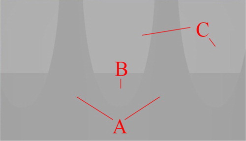
Figure 16. Result of the depth test algorithm and diagonally weighted algorithm.
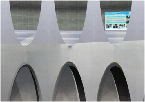
Three videos were projected and fused with the virtual scene to create a wide field of view AVE in the DESP. The result before being processed by the proposed algorithms is shown in and the drawbacks are the same as : video gaps (A and B), opaque glass, and incorrectly projected video textures. After being processed by the proposed algorithms, the video gaps are eliminated and the video textures change smoothly within the overlapping areas, as shown in .
Figure 17. Result of fusing three video textures before being processed by the proposed algorithms. A and B: obvious gaps in video textures.
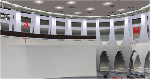
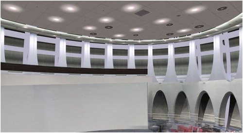
Figure 18. Result of fusing three video textures after being processed by the proposed algorithms.
4.2. 3D Visualization of a moving object
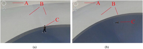
The extracted moving object was visualized as a rectangular polygon model and placed in the augmented virtual scene with the proposed moving object visualization method. As shown in , the videos were projected onto the 3D model of the Virtual Reality Hall (A) and fused together (B) by the multiple video texture fusion algorithm, and a rectangular model of the moving object (C) was located in the virtual scene. From the oblique view and the top view we can see that the polygon model can display the moving object realistically as if someone is walking in the 3D scene.
Figure 19. 3D visualization of the moving object. (a) Oblique view and (b) top view. A: 3D model in the virtual scene; B: fused video textures; C: rectangular model of the moving object.
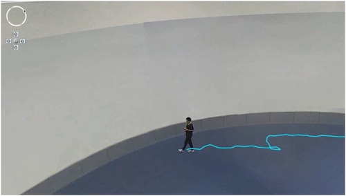
Furthermore, the sequential geographic coordinates were recorded and drawn out as a 3D line while updating the 3D position of the object model in the real time, as shown in . The 3D trajectory showed that the object model moved smoothly in the virtual scene.
Figure 20. Trajectory of the moving object. The trajectory was linked by the sequential geographic coordinates of the moving object model.
4.3. Efficiency analysis and discussion
The proposed algorithms were tested on a laptop which has an NVIDIA GeForce GT 730M graphics card with 1GB of memory.
First, the frame rates of conventional projective texture mapping were recorded as reference data. Different numbers (2, 4 and 6) of pictures and videos were projected onto different scenes with various triangles (from 340,000 to 2,040,000). In order to analyse the algorithms’ efficiency and exclude other influencing factors that may have appeared in the Digital Earth system, this test was run by a rendering engine based on OpenGL. As tabulated in , both picture textures and video textures performed excellently in different scenes, and the frame rates were almost 60 frames per second (fps) except a slight decline when using six videos in a scene with 2.04 million triangles. This shows that there is little difference between picture and video when used as a projected texture.
Table 2. Frame rates of the original projective texture mapping (fps).
After applying the proposed reverse projection culling algorithm, depth test algorithm, and diagonally weighted algorithm to a fragment shader, the frame rates were recorded (). The result shows the proposed algorithms barely affected rendering efficiency because the frame rates still remained at 60 fps except a slight decline as the reference data did. This slight decline resulted from the limited power of the GPU because the frame rate rose back to 59.9 fps when tested in a faster computer (HP Z800, NVIDIA Quadro FX5800 with 4GB of memory).
Table 3. Frame rates of proposed multiple video texture fusion algorithm (fps).
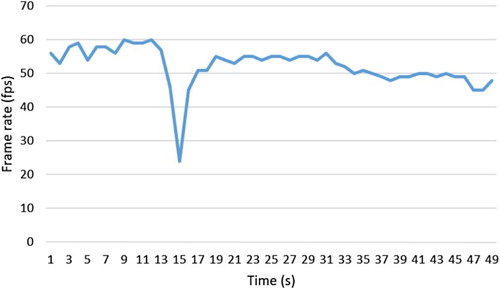
When running in the DESP, the frame rates of the four stages (viewing the 3D model only, fusing multiple videos, visualizing the moving object, and drawing the trajectory along with the moving object) were recorded consecutively, as shown in . At the first stage the DESP ran a 3D scene containing 144 thousand triangles at around 57 fps. The frame rate dropped suddenly at the 15th second when the system setup the virtual projectors and depth cameras, and the triangles of the scene grew to 1148 thousand because each depth camera had added the model of Virtual Reality Hall once. But the frame rate and the number of the triangles returned back immediately after the depth cameras were released. At the multiple video textures fusion stage, the frame rate kept around 53 fps, and fell a bit (less than 5 fps) when visualizing the moving object and drawing the trajectory in the real time. The result showed that the multiple video fusion and the moving object visualization methods barely affected rendering efficiency of the 3D scene except at the moment when the depth maps were captured.
Figure 21. Frame rates of video fusion and object visualization in the DESP. The stage of only viewing the 3D model: 1–13 s. The multiple video textures fusion stage: 17– 33 s. The moving object visualization stage: 34– 39 s. The trajectory visualization stage: 40–49 s.
5. Conclusion
This paper proposed a series of algorithms to build an AVE with a wide field of view based on a Digital Earth system, including improved algorithms for projective texture mapping (reverse projection culling and depth test algorithm), a diagonally weighted algorithm for fusing multiple video textures, and a method for visualizing a moving object and its trajectory. Then a realistic, wide field of view AVE based on the DESP was created by fusing three videos with the complex model of Virtual Reality Hall, visualizing the moving object, and drawing the trajectory in the 3D scene. The results show that the improved algorithms for projective texture mapping and multiple video texture fusion have high performance in fusing videos with 3D models, running a 3D scene containing two million triangles and six real-time videos at around 55 fps on a computer with 1GB of graphics card memory. When running in the DESP, the proposed algorithms also perform very well (above 45 fps) when fusing multiple video textures, locating a moving object and drawing its trajectory in the real time.
However, there are some problems and future improvements that should be taken into consideration carefully when creating an AVE by fusing video data with 3D models:
Fidelity of the 3D scene. If the 3D model is not realistic enough the projected texture might not match with the 3D model well, and the accuracy of a moving object’s position will be affected as the depth map is captured from the 3D scene. However, the complex and detailed 3D models will bring 3D rendering challenges to the system conversely. So it is better to distinguish clearly which models are used to fuse with videos and which are served as basic virtual scene.
Development of advanced object tracking methods. One moving object is extracted and visualized in this paper, but usually there will be more than one moving objects appearing in a video and it will bring some new problems, such as object recognition and occlusion. Besides, the lighting of the Virtual Reality Hall has barely affected the moving object extraction in this study, but the shadow problem will occur in most cases of moving object tracking. Thus some advanced methods for shadow removal, multi-object extraction and recognition should be developed in the Video Processing Module to get accurate and separate object silhouettes.
Incomplete moving object location. In the object visualization method, we supposed that the bottom of the moving object could be extracted at all times, but in fact a moving object, especially its bottom, is easily obscured by other things. In this case the proposed object location algorithm should be improved to calculate the object’s coordinates from an incomplete silhouette in future work.
Acknowledgements
The authors would like to thank the editors and anonymous reviewers for their valuable comments and suggestions. We also would like to thank Xiaoping Du, Jing Li, Zhenzhen Yan, Qin Zhan and Jian Liu for helpful discussions.
Disclosure statement
No potential conflict of interest was reported by the authors.
Additional information
Funding
References
- Agarwal, S., N. Snavely, I. Simon, S. M. Seitz, and R. Szeliski. 2009. “Building Rome in a Day.” Paper presented at the IEEE international conference on computer vision, Kyoto, Japan, September 29–October 2, 72–79.
- Bowring, B. 1976. “Transformation from Spatial to Geographical Coordinates.” Survey Review 23 (181): 323–327. doi: 10.1179/sre.1976.23.181.323
- Cao, S., and N. Snavely. 2014. “Minimal Scene Descriptions from Structure from Motion Models.” Paper presented at the IEEE conference on computer vision & pattern recognition, Columbus, Ohio, USA, June 23–28, 461–468.
- Chen, S. C., C. Y. Lee, C. W. Lin, et al. 2012. “2D and 3D Visualization with Dual-Resolution for Surveillance.” Paper presented at the proceedings of IEEE computer society conference on computer vision and pattern recognition workshops, Providence, Rhode Island, USA, June 16–21, 23–30.
- De Longueville, B., A. Annoni, S. Schade, N. Ostlaender, and C. Whitmore. 2010. “Digital Earth’s Nervous System for Crisis Events: Real-Time Sensor Web Enablement of Volunteered Geographic Information.” International Journal of Digital Earth 3 (3): 242–259. doi: 10.1080/17538947.2010.484869
- Everitt, C. 2001. “Projective Texture Mapping.” White paper, NVidia Corporation.
- Goodchild, M. F., H. Guo, A. Annoni, L. Bian, K. de Bie, F. Campbell, M. Craglia, et al. 2012. “Next-generation Digital Earth.” Proceedings of the National Academy of Sciences 109 (28): 11088–11094. doi: 10.1073/pnas.1202383109
- Gore, A. 1998. “The Digital Earth: Understanding Our Planet in the Twenty-First Century.” Australian Surveyor 43 (2): 89–91. doi: 10.1080/00050348.1998.10558728
- Guo, H. 2009. “Digital Earth: Ten Years” Development and Prospect.” Advances in Earth Science 24 (9): 955–962.
- Guo, H., X. Fan, and C. Wang. 2009. “A Digital Earth Prototype System: DEPS/CAS.” International Journal of Digital Earth 2 (1): 3–15. doi: 10.1080/17538940902746512
- Huang, B., L. Han, and L. Chen. 2011. “Integration and Application of Video Surveillance and 3DGIS.” Computer Engineering and Design 32 (2): 728–731.
- Liu, P., X. Sun, N. D. Georganas, and E. Dubois. 2003. “ Augmented Reality: A Novel Approach for Navigating in Panorama-Based Virtual Environments (PBVE).” Paper presented at the IEEE international workshop on haptic, audio & visual environments & their applications, Ottawa, Canada, September 20–21, 13–18.
- Luhmann, T., S. Robson, S. Kyle, and J. Boehm. 2013. Close-Range Photogrammetry and 3D Imaging. Berlin: de Gruyter.
- Ma, Y., G. Zhao, and B. He. 2012. “Design and Implementation of a Fused System with 3DGIS and Multiple-Videos.” Computer Applications and Software 29 (6): 109–104.
- Macedonio, M. F., T. D. Parsons, R. A. Digiuseppe, B. K. Weiderhold, and A. A. Rizzo. 2007. “Immersiveness and Physiological Arousal within Panoramic Video-Based Virtual Reality.” Cyberpsychology & Behavior the Impact of the Internet Multimedia & Virtual Reality on Behavior & Society 10 (4): 508–515.
- Milosavljević, A., A. Dimitrijević, and D. Rančić. 2010. “GIS-augmented Video Surveillance.” International Journal of Geographical Information Science 24 (9): 1415–1433. doi: 10.1080/13658811003792213
- Neumann, U., S. You, J. Hu, B. Jiang, and J. W. Lee. 2003. “Augmented Virtual Environments (AVE): Dynamic Fusion of Imagery and 3D Models.” IEEE virtual reality’03 61–67.
- Remondino, F., and M. Gerke. 2015. “ Oblique Aerial Imagery – A Review.” Paper presented at proceedings of 55th photogrammetric week, Stuttgart, Germany, September 7–11, 75–83.
- Riveiro, B., P. Morer, P. Arias, and I. de Arteaga. 2011. “Terrestrial Laser Scanning and Limit Analysis of Masonry Arch Bridges.” Construction & Building Materials 25 (4): 1726–1735. doi: 10.1016/j.conbuildmat.2010.11.094
- Rost, R. J. 2009. OpenGL Shading Language. 3rd ed. Boston: Addison-Wesley.
- Sebe, I. O., J. Hu, S. You, and U. Neumann. 2003. “ 3D Video Surveillance with Augmented Virtual Environments.” Paper presented at the IWVS ‘03 first ACM SIGMM international workshop on video surveillance, Berkeley, California, November 02–08, 107–112.
- Segal, M., C. Korobkin, R. Van Widenfelt, J. Foran, and P. Heaberli. 1992. “Fast Shadows and Lighting Effects Using Texture Mapping.” Proceedings of SIGGRAPH ‘92, Computer Graphics 26 (2): 249–252. doi: 10.1145/142920.134071
- Silva, J. R., T. T. Santos, and C. H. Morimoto. 2011. “Automatic Camera Control in Virtual Environments Augmented Using Multiple Sparse Videos.” Computers & Graphics 35 (2): 412–421. doi: 10.1016/j.cag.2011.01.012
- Stauffer, C., and W. E. L. Grimson. 2000. “Learning Patterns of Activity Using Real Time Tracking.” IEEE Transactions on Pattern Analysis and Machine Intelligence 22 (8): 747–757. doi: 10.1109/34.868677
- Szeliski, R. 2006. “Image Alignment and Stitching: A Tutorial.” Foundations and Trends in Computer Graphics and Vision 2 (1): 1–104. doi: 10.1561/0600000009
- Wang, L., S. You, and U. Neumann. 2007. “Single View Camera Calibration for Augmented Virtual Environments.” Paper presented at IEEE virtual reality conference, Charlotte, North Carolina, USA, March 10–14, 255–258.
- Weiss, P. L., D. Rand, N. Katz, and R. Kizony. 2004. “Video Capture Virtual Reality as a Flexible and Effective Rehabilitation Tool.” Journal of Neuroengineering & Rehabilitation 1: 12. doi:10.1186/1743-0003-1-12
- Yang, J. C., C. H. Chen, and M. Chang Jeng. 2010. “Integrating Video-Capture Virtual Reality Technology into a Physically Interactive Learning Environment for English Learning.” Computers & Education 55 (3): 1346–1356. doi: 10.1016/j.compedu.2010.06.005
- Yilmaz, A., O. Javed, and M. Shah. 2006. “Object Tracking: A Survey.” ACM Computing Surveys 38 (4): 81–93. doi: 10.1145/1177352.1177355
- Zhou, Y., P. Liu, J. You, and Z. Zhou. 2014. “Streaming Location-Based Panorama Videos into Augmented Virtual Environment.” Paper presented at international conference on virtual reality & visualization, Shenyang, China, August 30–31, 208–213.