
 ?Mathematical formulae have been encoded as MathML and are displayed in this HTML version using MathJax in order to improve their display. Uncheck the box to turn MathJax off. This feature requires Javascript. Click on a formula to zoom.
ABSTRACT
The combination of virtual reality (VR) and virtual globes – VR globes – enables users to not only view virtual scenes in an immersive manner at any location on Earth but also directly interact with multi-scale spatial data using natural behaviors. It is an important direction for the future development of 3D GIS and geovisualization. However, current VR navigation are primarily based on small real spaces. For virtual globes, which are 3D multi-scale globe environment, the realization of VR navigation in the multi-scale virtual globe space within a limited real space is the first problem that needs to be addressed. A multi-scale VR navigation method that consists of two algorithms is proposed in this study. The first algorithm maps the real space to the virtual globe space and connects the VR user with the VR viewpoint. The second algorithm is an octree structure-based viewpoint correction algorithm that is proposed to correct the location of the moving VR viewpoint in real time. The proposed method is validated by experimentation. The experimental results indicate that the proposed method enables a VR user to interactively view the 3D multi-scale globe environment and lays a foundation for human–computer interaction in VR globes.
1. Introduction
Virtual reality (VR) is a new human–computer interaction technology that immerses the user in a virtual world using interactive devices, such as head-mounted display (HMD) systems and hand controllers. In the geographic information field, the application of VR effectively mitigates the deficiency of traditional geographic information – it is passively perceived – and enables people to actively analyze the deep meaning contained in geoscience data. VR is an important direction for future development of three-dimensional (3D) geographic information systems (GISs) and geographic information visualization (Helbig et al. Citation2014; Kamel Boulos et al. Citation2017; Kellogg et al. Citation2008; Simpson et al. Citation2016; Verbree et al. Citation1999).
As a new-generation 3D geographic information integration and visualization platform, Virtual globes can realize the unified management and visualization of multi-source multi-scale spatial data, including image, topographic, atmospheric, oceanic and urban data (Goodchild et al. Citation2012; Mahdavi-Amiri, Alderson, and Samavati Citation2015). It is Widely used in geoscience education(De Paor et al. Citation2017; Martínez-Graña et al. Citation2014), virtual tourism(González-Delgado et al. Citation2015), hazard analysis(Silva et al. Citation2017), environmental assessment (Santos-Francés et al. Citation2017), and travel path planning (Martínez-Graña et al. Citation2017). The combination of VR and virtual globes – VR globes – can represent global to local geographic environments and outdoor to indoor geographic environments and enable people to view virtual scenes in an immersive manner at any location on Earth. In addition, VR globes also expand the traditional human–computer interactivity from a two-dimensional (2D) screen space to a 3D real space (Kellogg et al. Citation2008). Thus, complex interactive strategies can be designed with VR globes to satisfy the requirements of the application of different spatial data. VR globes can realize interactive visualization of multi-source spatial data.
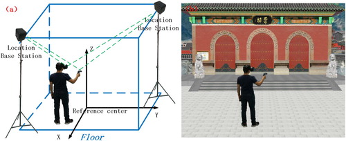
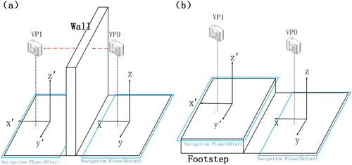
However, existing VR navigation systems are primarily based on small real spaces. As shown in , the VR system directly maps the user’s movements to the virtual space by location tracking to achieve the goal of navigation in the real space and the virtual space simultaneously. Due to the limitations of available location tracking techniques and space, the area within which the user can move in the real space cannot be infinitely extended (Suma et al. Citation2015). For VR globes, which are 3D visualization systems oriented to global geographic information, the realization of VR navigation in the entire virtual globe space within a limited real space is the first problem that needs to be addressed.
Figure 1. Simultaneous navigation in a real space and a virtual space: (a) a user navigates in a real space; (b) a user navigates in a virtual space.
Multi-scale navigation, which is the main feature of virtual globe systems, differentiates virtual globe systems from traditional 3D visualization systems. Existing desktop virtual globe systems (Pirotti et al. Citation2017) generally control the range of view and the fineness of a scene by adjusting the viewing distance (foreshortening). As shown in (a), when the field of view (FOV) and aspect ratio (h/w) of the frustrum remain constant, the greater the distance is between the viewpoint and the globe environment, the larger the area of observation.
Figure 2. Multi-scale navigation in a virtual globe environment realized by altering the viewing distance.
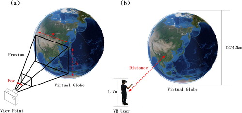
Under this condition, as shown in (b), if the VR user (height: ca. 1.7 m; FOV of both eyes: ca. 110°) wishes to view the entire globe environment (diameter: ca. 12,742 km), his/her minimum viewing distance should be greater than 4,500 km:
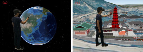
This calculation yields the separation between the VR user and the globe environment in space, i.e. the VR user can only view the virtual environment from a long distance but cannot directly interact with the virtual environment. As shown in , VR navigation (Kellogg et al. Citation2008; Oprean Citation2015) requires that the user be able to interact with the virtual environment through natural behaviors while viewing the virtual environment. Therefore, the realization of multi-scale VR navigation in VR globes is the second problem that needs to be addressed.
Figure 3. A VR user interacts with a multi-scale virtual environment: (a) a VR user touches and rotates the globe with a hand controller; (b) a VR user freely walks through a city and collects buildings.
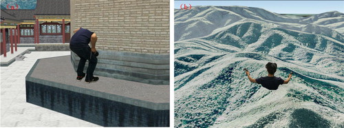
The VR immersion is reflected in the accuracy of navigation in the virtual environment in addition to its fidelity. The user’s experience will be significantly adversely affected if the viewpoint goes into a wall or the ground, as shown in . However, existing desktop virtual globe systems primarily enable the user to observe the environment from a high bird’s-eye view (Pirotti et al. Citation2017) and relatively rarely consider collision detection when the viewpoint moves, which produces major deficiencies when the user views near-surface or indoor scenes. Therefore, accurately and rapidly correcting the viewpoint and ensuring that the viewpoint appears at the right location during VR navigation is the third problem that needs to be addressed.
Figure 4. Collision between the VR viewpoint and virtual scenes: (a) the VR viewpoint goes into a wall because the obstruction of the wall is not considered; (b) the VR viewpoint is gradually covered by a mountain because the topographic relief is not considered.
Three problems concerning navigation in VR globes exist, namely, global navigation, multi-scale navigation and precision navigation. To address the first two problems, a real space-to-virtual globe space-mapping algorithm is proposed. This algorithm maps the real space to the virtual globe space and connects the VR user in the real space with the VR viewpoint in the virtual globe space to achieve the goal of driving the movement of the viewpoint by the user’s behaviors. To address the third problem, a real-time VR viewpoint correction algorithm is proposed. This algorithm divides a 3D globe environment into an octree structure and ensures that collision detection is only performed between the VR viewpoint and the nearest 3D scenes and corrects the VR viewpoint in real time based on the collision detection results, which prevents the VR viewpoint from going into a wall or the ground.
2. Related work
The realization of VR navigation in an infinite virtual space within a limited real space has always been a focus of VR research. The existing mainstream VR systems primarily realize VR users’ navigation in large virtual environments using the following five modes: teleportation, path tracking, redirected walking, posture-based driving and hand controller-guiding modes (Bowman et al. Citation2008; Käser, Parker, and Bühlmann Citation2016; Mihelj, Novak, and Beguš Citation2014).
Teleportation instantly enables the user to orient his/her viewpoint to a specified location by picking up mini-maps. Through the combination of teleportation and location-tracking techniques, the user can freely move within a certain range from the teleported location. This mode can be easily implemented and is the most commonly employed navigation mode in all mainstream VR systems, including VR-GIS. For instance, Kellogg et al. (Citation2008) virtually entered the inside of a seismic field and observed the seismogenic faults by teleportation. Helbig et al. (Citation2014) rapidly switched between two viewpoints via teleportation when viewing 3D meteorological data. However, the data processed in the previously mentioned studies were generally fixed in terms of scale and range; thus, the support of complex environment navigation technology was not required. VR globes have an extensive range of applications, from the globe surface to fine indoor environments, and often processes multi-scale data. Consequently, teleportation can hardly satisfy the application requirements of VR globes.
In the path tracking mode, the viewpoint navigates along a preset path, and the user can look around by turning the HMD system but cannot leave the path (Mihelj, Novak, and Beguš Citation2014). This mode has relatively low flexibility and requires the construction of a large number of paths in advance; thus, its application is limited.
Redirected walking enables the VR user to navigate in a large virtual environment by walking in a circle in a real space by misguiding the viewpoint (Azmandian et al. Citation2016; Bruder et al. Citation2012; Suma et al. Citation2015). This mode has an extensive range of applications and is a popular direction of research on VR navigation. However, available redirected walking algorithms rely on the network information at the location of the viewpoint. For VR globes, constructing a network for 3D scenes of all scales and regions is relatively difficult.
The posture-based driving mode binds particular postures of the human body with the existing movement rules for the viewpoint (e.g. advancing forward, retreating and accelerating) in advance; once the user produces a specific posture, the viewpoint will move according to the corresponding rule (Çöltekin et al. Citation2016; Roupé, Bosch-Sijtsema, and Johansson Citation2014). This mode primarily improves the VR navigation on the interactivity level – it upgrades traditional 2D interaction to 3D interaction. Its movement rules for the viewpoint is consistent with the movement rules for the viewpoint in existing desktop 3D systems. For instance, Kamel Boulos et al. (Citation2011) bound gestures with the translation, rotation and zooming of the viewpoint in a commercially available desktop virtual globe system and controlled the virtual globe by gestures. As previously mentioned, when the VR user views a large environment, the available movement rules for the viewpoint in virtual globe systems will create a separation between the VR user and the virtual environment in space. As a result, the VR user cannot directly interact with the virtual environment through natural behaviors.
Compared with the posture-based driving mode, guiding the viewpoint with a hand controller is more flexible and can be implemented using various approaches. For example, the user can apply a hand controller to emit a ray that intersects with the 3D scene, instantly move the viewpoint to the point of intersection and then use the hand controller to drag the scene or direct the flight through the viewpoint along the hand controller. Hand controller-guidance is employed in the Google Earth VR launched in 2016 (Käser, Parker, and Bühlmann Citation2016). Similar to postures, hand controllers are only a means of interaction.
As described above, the teleportation is the easiest implementation, but it does not support the continuous roaming of 3D multi-scale globe environment, which is only a kind of auxiliary navigation methods. Path tracking can effectively avoid collision between the viewpoint and 3D scenes, but it is inflexible because users can only move along the pre-established route. The redirected walking has the best prospects for application, but the existing technology needs to build a large number of road networks in advance, which is difficult to apply to the virtual globe systems. Posture-based driving and hand controller-guiding primarily improve the way to interact with VR navigation, but their movement rules for the viewpoint are consistent with the movement rules for the viewpoint in existing desktop 3D systems. Instead of the mode of interaction, the most distinct feature of the Google Earth VR is that the user can not only view a multi-scale virtual environment but also immersively interact with the virtual environment using natural behaviors. As a commercial software program, the details of technical realization of the Google Earth VR are not known to the public. In addition, the currently available Google Earth VR includes global to urban scales but does not contain indoor or street scenes that better reflect the application value of VR. The Google Earth VR also fails to adequately consider the viewpoint–virtual scene collision problem during the navigation process.
The remainder of this paper is organized as follows: Section 3 describes the methodology in this study. Section 3.1 introduces the process of constructing an algorithm that maps a real space to a virtual globe space and realizing a VR user’s multi-scale navigation in a virtual globe environment. Section 3.2 describes how to correct a moving VR viewpoint and realize precision navigation in near-surface or indoor scenes. Section 4 presents the details of the experiments performed to validate the proposed method. Section 5 provides the conclusions and an outlook.
3. Methodology
3.1. Real space-to-virtual globe space-mapping algorithm
As shown in (a), all movements of the VR user are based on a Cartesian coordinate system with the reference center of the location tracking system as the origin. Conversely, existing virtual globe environments are based on an Earth-centered and Earth-fixed coordinate system ((a)). Therefore, the basis for mapping a real space to a virtual globe space is the transformation between these two coordinate systems. In this study, two spatial objects – a scene plane and a navigation plane – are designed to simplify the mapping problem ().
Figure 5. (a) Scene plane and (b) navigation plane.
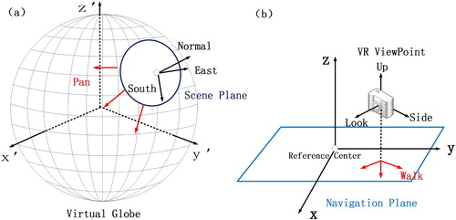
The scene plane is the tangent plane of a point on the virtual globe surface, which is equivalent to a local scene of the virtual globe. The normal vector of the scene plane coincides with the normal vector of the virtual globe ellipsoid. The navigation plane can be viewed as the ground in the real space, whose origin is the reference center of the location tracking system. When the HMD system moves on the ground, the VR viewpoint will simultaneously move on the navigation plane. This design simplifies a complex space-mapping problem into a two-plane relative location problem, i.e. the VR user’s navigation in the virtual globe environment can be realized as long as the relative location relationship between the scene and navigation planes is determined.
According to the requirements for navigation in a VR globe, the following four relative location relationships are designed:
Aligned: To enable the user to view scenes of the virtual globe at any location, as shown in (a), the origins of the navigation and scene planes are set to coincide and the axial relationships are maintained unchanged. When the scene plane pans on the virtual globe surface, the navigation plane will also pan synchronously to keep its location aligned with the location of the scene plane. As a result, the scene observed from the VR viewpoint will also change. This relationship can be represented by the following matrix:
(2) Rotational: To enable the user to view scenes of the virtual globe from various angles, the navigation plane is rotated around the Y-axis to set the navigation plane parallel or perpendicular to the scene plane. When the two planes are parallel, the user views the virtual globe environment from an elevation view ((a)). When the two planes are perpendicular, the user views the virtual globe environment from a bird’s-eye view ((b)). This relationship can be represented by the following matrix:
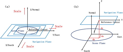
(3) Scaling: To enable the user to view scenes of the virtual globe of various scales, the scaling ratio N of the navigation plane is adjusted, i.e. one meter on the navigation plane corresponds to N meters on the scene plane (N is set by the user). (a) shows the specific result. As the scaling ratio N increases, the viewing and movable range of the user will increase. Thus, the goal of enabling the user to interact with 3D scenes of various scales is achieved. This relationship can be represented by the following matrix:
(4) Offset: To achieve precision VR viewpoint-guided navigation, the location of the VR viewpoint is corrected (i.e. temporarily offset) when it goes into a wall or the ground. This correction is achieved by offsetting the origins of the navigation and scene planes ((b)). This approach is advantageous because it offsets the VR viewpoint while maintaining the relative locations of the VR viewpoint and the reference center; thus, it will not affect the previously mentioned scaling relationship. This relationship can be represented by the following matrix:
To establish an algorithm that maps a real space into a virtual globe space, the previously mentioned four location relationships need to be merged; i.e. the scaling, rotational, offset and aligned matrix transformations are implemented in succession:All vectors or matrices in a real space can be mapped into a virtual globe space by post-multiplying them by the
. For example, the VR viewpoint on the virtual globe surface (left and right eyes, represented by matrices) is as follows:
Where
is the relative locations of the HMD system and the reference center; Side, Up and Look are the orientations of the HMD system ((b)); and IPD is the pupillary distance. These parameters are provided by the VR system. Note that the orientations in viewpoint matrix need to be normalized after scaling.
Figure 6. Relative location relationships between the scene and navigation planes: (a) aligned; (b) rotational.
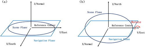
Figure 7. Relative location relationships between the scene and navigation planes: (a) scaling; (b) offset.
In an actual application, the VR user can navigate in 3D scenes of the entire VR globe of various scales at various angles by adjusting the location of the origin of the scene plane, the rotational angle θ of the navigation plane with respect to the scene plane and the scaling ratio N of the navigation plane with respect to the scene plane using an interactive device, such as a hand controller.
3.2. Octree structure-based VR viewpoint correction algorithm
Multi-scale VR navigation in a virtual global environment is realized using the algorithm described in Section 3.1, which maps a real space to a virtual globe space. However, this navigation process does not consider the collision between the viewpoint and 3D scenes (only providing dx, dy, dz as interface parameters without explaining how to determine them). As a result, the viewpoint can easily go into a wall or the ground, which will significantly negatively affect the user’s experience in near-surface and indoor navigation. A VR viewpoint correction algorithm is proposed based on the discussion in Section 3.1.
Viewpoint correction means that whether the location of the viewpoint, when moving, collides with a 3D scene is determined by collision calculation. If they collide, the viewpoint is separated from the 3D scene according to certain rules to enable the viewpoint to appear at the correct location.
As the scene complexity increases, the collision calculation load also increases. In a VR environment, the location of the VR viewpoint will be frequently updated as the HMD system moves. In this circumstance, a slow viewpoint correction rate will significantly affect the total drawing efficiency. To improve the efficiency, existing collision algorithms generally partition the space prior to collision detection into structures such as binary space-partitioning trees, uniform grids, octrees and quadtrees. Ensuring that collision calculation is only performed between the test target and nearby 3D scenes effectively reduces the collision calculation load. However, the previously mentioned space-partitioning algorithms are oriented to small local scenes (Luo et al. Citation2011) and cannot be directly applied to multi-scale 3D global scenes. To address this issue, Luo et al. (Citation2011) proposed a ‘VGIS-COLLIDE’ algorithm. This algorithm integrates a conventional quadtree with a global geographic space and uses geographic coordinates instead of rectangular coordinates to partition the space into a quadtree structure. The ‘VGIS-COLLIDE’ algorithm can seamlessly cover global geographic space while having the structural features of a quadtree. However, the quadtree structure can only be used to partition the globe surface into 2D regions; the elevation attribute of geographic space (e.g. the story attribute of indoor scenes) is disregarded. Based on the ‘VGIS-COLLIDE’ algorithm, an improved algorithm is proposed in this study, which partitions the 3D globe environment into an octree structure instead of a quadtree structure.
3.2.1. Octree structure-based globe space partitioning
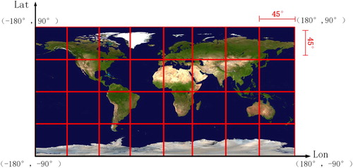
The proposed 3D globe space partition method is mainly referred to the 2D map partition method in OGC Web Map Tile Service (WMTS), as shown in , WMTS partitions the entire 2D globe space into dispersed subspaces with the same longitudinal and latitudinal spans.
Figure 8. The 2D map partition method in OGC Web Map Tile Service.
After extending to 3D, the height of each subspace must be considered, as shown in (a), the proposed method partitions the entire 3D globe space into dispersed subspaces with the same longitudinal and latitudinal spans and height at first
Figure 9. Octree structure-based globe space partitioning.
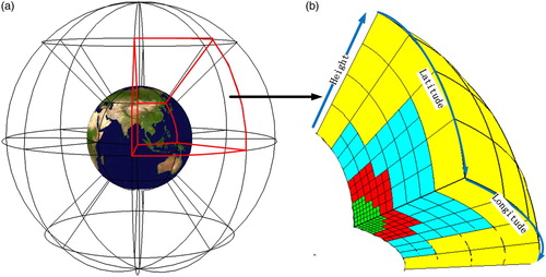
As shown in (a), starting from the point at a longitude of 180° west and a latitude of 90° south, this algorithm partitions the entire spherical space from south to north and west to east into 32 subspaces with the same longitudinal and latitudinal spans and height. To ensure that the subspaces are as regular as possible, the height of each subspace isWhere R is the radius of the Earth (ca. 6,371 km) and
is the ratio of a circle’s circumference to its diameter (ca. 3.1415926).
These subspaces constitute level 0 of the octree structure. Internally, each subspace is iteratively partitioned by evenly dividing the longitude, latitude and height ((b)) to achieve the goal of seamlessly covering the entire 3D geographic space.
In a practical application, considering that virtual globe systems generally load scenes in a multi-threaded asynchronous mode, the octree structure is dynamically established in this study; i.e. the octree structure is updated each time a drawing object (mesh) is loaded into the scene. The octree is traversed, and each drawing object is inserted into the corresponding node of the octree. If the corresponding node is a leaf node and the total number of internal vertices exceeds the threshold value, the node is split. Refer to algorithm 1 for details.
The judging criterion in Step 4 is established to avoid an overly central distribution of drawing objects, which can cause frequent splitting of the octree (50% is an empirical value).
3.2.2. VR viewpoint correction
Algorithm 1 reorganizes the 3D globe environment into an octree structure. Therefore, the first step of VR viewpoint correction is to traverse the octree to find the octree leaf node where the VR viewpoint is located and extract the drawing objects (3D scene) from the octree leaf node. Considering that space partitioning starts from the globe, an overly central distribution of drawing objects will produce an overly large tree depth, which affects the search efficiency. Therefore, the conventional octree traversal approach that starts from the root node and proceeds from top to bottom is not employed. Instead, the search for the octree leaf node starts from the node where the VR viewpoint is located in the previous frame and proceeds from bottom to top to bottom. This approach is feasible because the movement of the VR viewpoint is continuous; thus, the node where the VR viewpoint is located in the previous frame is undoubtedly adjacent to the node where the current VR viewpoint is located. The search is faster when starting from the adjacent node compared with starting from the root node. Refer to algorithm 2 for details.
After the drawing objects (3D scene) near the viewpoint are obtained using algorithm 2, the next step is to perform collision calculations between the viewpoint and these drawing objects and, based on the results, correct the viewpoint to achieve precision VR viewpoint-guided navigation in near-surface or indoor scenes.
Based on Section 3.1, the movement of the VR viewpoint is primarily realized by two modes: (1) moving the navigation plane in the virtual space and indirectly moving the VR viewpoint; (2) moving the HMD system in the real space and directly moving the VR viewpoint. Therefore, specific viewpoint correction algorithms are designed for these two modes of moving the VR viewpoint.
For the first mode of moving the VR viewpoint, consider that the movement of the navigation plane is continuous, if the viewpoint is found to collide with the scene (e.g. when encountering an object, such as a wall), the viewpoint and the scene can be separated by rolling back the navigation plane to its location in the previous frame. This separation can be achieved with the following steps:
Step 1. Let be the motion vector of the navigation plane, and let
be the location of the current VR viewpoint. Then, the location of the VR viewpoint after it moves is
.
Step 2. Determine if an intersection point exists between the line that connects VP0 and VP1 and the 3D scene. If an intersection point exists, which indicates that the viewpoint collides with the 3D scene during its movement ((a)), decline the navigation plane’s request for movement and roll the VR viewpoint back to .
Figure 10. (a) When moving the navigation plane will cause a collision between the VR viewpoint and the scene, the request for movement is declined to prevent the VR viewpoint from going into the wall; (b) when moving the navigation plane will not cause a collision between the VR viewpoint and the scene, the request for movement is accepted and the navigation plane is lifted upward to enable its origin to adjoin the local scene to prevent the VR viewpoint from sinking into the ground.
Step 3. Accept the navigation plane’s request for movement if an intersection point does not exists. Based on Section 3.1, to satisfy the aligned location relationship, the origin of the navigation plane after the movement needs to adjoin the local scene (scene plane). For relatively high terrain, the VR viewpoint will be lifted upward to a certain level to prevent it from sinking downward ((b)).
For the second mode of moving the VR viewpoint, because a movement of the HMD system has already occurred in the real space and cannot be rolled back, the VR viewpoint can be separated from the scene by offsetting its location in the virtual space. In this study, the navigation plane is offset (as mentioned in Section 3.1) instead of directly offsetting the VR viewpoint. This can be achieved with the following steps:
Step 1. Let VP1 be the location of the current VR viewpoint, and let VP0 be the location of the VR viewpoint in the previous frame. Calculations are performed to determine whether an intersection point exists between the line that connects VP0 with VP1 and the 3D scene.
Step 2. Offset the navigation plane in the horizontal direction if there is an intersection point ((a)). The offset vector (dx, dy) is the projection of the direction vector from VP1 to the intersection point in the local scene.
Figure 11. (a) If the VR viewpoint goes into a wall, the navigation plane is horizontally offset. As a result, the VR viewpoint horizontally moves from VP1 to VP2. (b) If the VR viewpoint sinks into the ground, the navigation plane is vertically offset. As a result, the VR viewpoint vertically moves from VP1 to VP2.
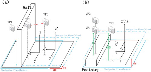
Step 3. Offset the navigation plane in the vertical direction if an intersection point does not exist ((b)). The amount of the offset iswhere D is the vertical distance from VP1 to the local scene, H is the height of the HMD system in the real space, and N is the scaling ratio of the navigation plane with respect to the scene plane.
4. Experiments and discussions
To verify the validity of the proposed method, experiments were conducted on osgEarth, which is an open-source virtual globe platform, in the following software and hardware environments: Windows 7 32-bit, OpenGL and OpenVR, as well as an Intel® CoreTM i7-6700 K central processing unit, an NVIDIA GeForce 1070 graphics card, 8 GB memory and an HTC VIVE head-mounted VR system.
Regarding the experimental data, the images were extracted from the ESRI Imagery World 2D Map, the topographic data were extracted from the ReadMap Terrain Tiles, and the building data were extracted from the 3D city model of a scenic area in Shanxi, China.
– show the imagery observed from the VR viewpoint during multi-scale navigation in the virtual globe environment.
Figure 12. Imagery observed from the VR viewpoint when the scaling ratio N is set to 5,000,000.
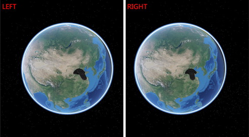
Figure 13. Imagery observed from the VR viewpoint when the scaling ratio N is set to 20,000.
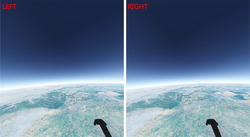
Figure 14. Imagery observed from the VR viewpoint when the scaling ratio N is set to 100.
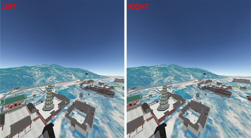
Figure 15. Imagery observed from the VR viewpoint when the scaling ratio N is set to 15.
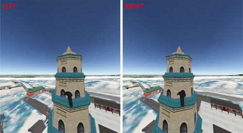
Figure 16. Imagery observed from the VR viewpoint when the scaling ratio N is set to 1.
shows the imagery observed when the scaling ratio N of the navigation plane is adjusted to the globe scale. On this scale, the entire globe is displayed to the user in a form similar to a terrestrial globe, where the user can directly touch and rotate the entire globe with his/her hands.
shows the imagery observed by reducing the scaling ratio and rotating the viewing angle based on the imagery shown in . On this scale, the VR user can rapidly travel among different countries and territories. This scale is suitable for processing geographic information data of large areas (e.g. meteorological and oceanic data).
shows the imagery observed by reducing the scaling ratio to the urban scale. On this scale, an entire city is displayed in front of the VR user in a form similar to micro-models. The VR user can freely move between the buildings and bend down to collect them. Thus, this scale is suitable for urban planning. For example, on this scale, urban planners can adjust the location and size of a building and observe the effects of the adjustment on the nearby environment and traffic.
shows the imagery observed by moving the location of the origin of the scene plane and reducing the scaling ratio based on the imagery shown in . On this scale, the VR user is very close to the buildings in terms of size and can easily edit the 3D vectors of the building surface (e.g. drawing the vector contour of a building).
shows the imagery observed when the scaling ratio is reduced to 1. Because this scale is consistent with the actual scale, the immersion and fidelity are high. This mode of navigation is essential in realizing virtual tourism.
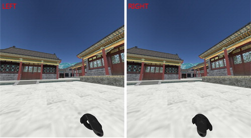
shows the imagery observed during indoor navigation using the proposed method (taken from the display of the HMD system in front of the user’s left eye).
Figure 17. Indoor navigation performance.
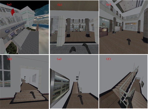
As shown in , compared with general navigation from a high bird’s eye view, additional consideration should be given to the effects of 3D scenes on the movement of the viewpoint (e.g. the viewpoint is lifted upward when encountering steps and blocked when encountering an obstacle) in indoor navigation. These effects are rarely considered in the navigation algorithms applied in existing virtual globe systems, which causes major deficiencies in near-surface or indoor navigation. The proposed navigation algorithm can ensure a distance between the viewpoint and steps, railings and walls and enables the VR user to navigate in a virtual indoor environment in a manner that is more consistent with the manner in which the VR user would navigate in the real indoor environment.
shows the imagery observed during multi-scale navigation in the Google Earth VR.
Figure 18. Google Earth VR (a) global-scale image and (b) building-scale image.
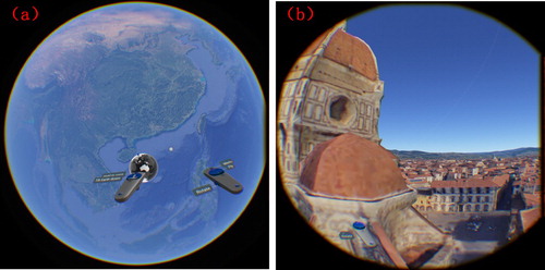
The current Google Earth VR only offers navigation in global ((a)) to building ( (b))-scale scenes; it does not provide navigation in street () and indoor () scenes. Multi-scale navigation is achieved in this study by reducing the scaling ratio N of the navigation plane. Seamless switching among various scales is realized by controlling the scaling ratio N. With the proposed algorithm, integrated navigation in outdoor and indoor scenes around the globe is achieved.
shows the total drawing time for each frame and the navigation time during the entire navigation process from the globe to the indoor scenes (–), which demonstrates the efficiency of the proposed navigation algorithm.
Figure 19. Total drawing time and navigation time during the navigation process.
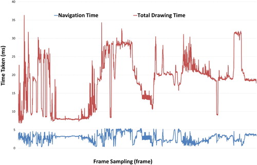
The navigation time includes the time required to map the VR user from the real space to the virtual globe space, the viewpoint correction time and the message response time of the hand controller or the HMD system. The total drawing time is the total time required to draw a frame. As demonstrated in , regardless of how the scene changes, the navigation time is within 5 ms because the 3D globe environment is partitioned into an octree structure. Collision calculation is only performed between the VR viewpoint and the nearby 3D scenes with a limited number of vertices for the same period of time, which effectively limits the effects of scene complexity on the navigation time.
In order to verify the robustness of the proposed navigation method, records the total drawing time and navigation time with different scene complexities (represented by the total number of vertices in the scene).
Figure 20. Total drawing time and navigation time with different scene complexities.
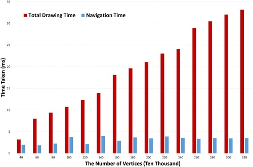
As demonstrated in , with the increase of the number of vertices, the total drawing time is rising linearly while the navigation time is still within 5 ms. This result shows that the proposed method can avoid the impact of scene complexity during the process of navigation, which is consistent with the conclusion of .
shows the comparison of the time consumed when the VR viewpoint is corrected based on different space-partitioning algorithms, which verifies the effectiveness and necessity of partitioning the 3D globe environment into an octree structure. The ‘VGIS-COLLIDE’ algorithm proposed by Luo et al. (Citation2011) – a quadtree structure-based space-partitioning algorithm – is employed for comparison. This space-partitioning algorithm is also oriented to 3D globe environments and is relatively similar in terms of the application field to the algorithm proposed in this study.
Figure 21. Comparison of the viewpoint correction time when different space-partitioning algorithms are employed.
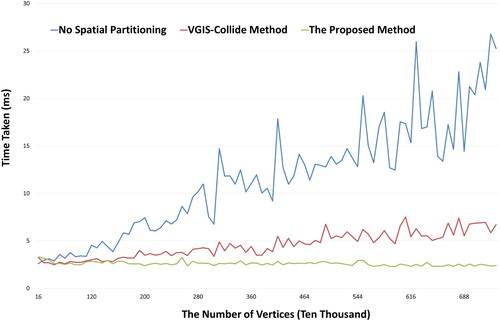
As demonstrated in , when no space partitioning is performed, the viewpoint correction time linearly increases with scene complexity (number of vertices), which eventually affects the drawing efficiency. Space partitioning can effectively avoid this issue. Regarding the two space-partitioning algorithms, because the urban building data employed in the experiment contain a large amount of indoor and story structure data, the octree structure-based space-partitioning algorithm can evenly partition the 3D environment and has higher stability and efficiency compared with the quadtree structure-based space-partitioning algorithm.
The current space-partitioning structure needs to be updated each time a drawing object (mesh) is loaded. The update time of the two space-partitioning algorithms is compared () to determine whether frequent updating will affect the system efficiency.
Figure 22. Comparison of the update time of the two space-partitioning algorithms.
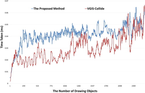
As demonstrated in , the update time of the octree structure-based space-partitioning algorithm proposed in this study is maintained at approximately 0.045 ms; however, it is higher than the update time of the existing quadtree structure-based space-partitioning algorithm. Considering that the loading time is approximately 100 ms for a mesh with 1,000 vertices that contains no texture, the update of the space-partitioning structure will not affect the loading of drawing objects. Because the quadtree structure-based space-partitioning algorithm cannot evenly partition a 3D space, the depth of the quadtree will increase faster than the depth of the octree as the number of drawing objects in the scene increases, which eventually causes the update time of the quadtree structure-based space-partitioning algorithm to approach or exceed the update time of the octree structure-based space-partitioning algorithm.
5. Conclusions and future work
Compared with the existing desktop 3D-GIS system, VR globes combine the advantages of virtual reality and virtual globes. VR globes not only enable GIS users to view virtual scenes in an immersive manner at any location on Earth but also enable GIS users to interact directly with the spatial data through natural behaviors, which fully mobilize the active learning ability of GIS users. VR globes are an important direction for future development of 3D GIS and geographic information visualization. However, for VR globes, the first problem need to be addressed is to provide the VR navigation in entire virtual globe environment. Therefore, a multi-scale VR navigation method is proposed. This method primarily contains two algorithms: (1) A real space-to-virtual space mapping algorithm. Using this real space-to-virtual space mapping algorithm, multi-scale navigation in the entire virtual globe environment is realized for VR users. (2) An octree structure-based viewpoint correction algorithm. By correcting the location of the VR viewpoint in real time, precision navigation in near-surface and indoor environments is realized for VR users. Compared with existing methods, the proposed method has the following advantages:
In global navigation, the mapping from a real space to a virtual globe space is realized using a unified space-mapping algorithm. A VR user can rapidly and continuously move the VR viewpoint to any location on the globe by adjusting the space-mapping parameters using an interactive device, such as a hand controller.
In multi-scale navigation, the existing virtual globe systems (Google Earth Desktop, ArcGlobe, SkyLine, WorldWind, osgEarth and so on) enable a VR user to observe 3D scenes of various scales by adjusting the viewing distance. When viewing a large scene in these systems, the VR user is separated from the scene in space. In this study, multi-scale navigation is achieved by adjusting the scaling ratio of the VR user with respect to the scene. This approach allows the VR user to be in the virtual environment throughout the navigation process and directly interact with the multi-scale environment through natural behaviors.
In regard to precision navigation, the existing virtual globe systems seldom consider the viewpoint–scene collision problem, resulting in deficiencies in navigation in near-surface or indoor environments. In this work, a VR viewpoint correction algorithm is designed to correct the location of the viewpoint in real time. In addition, to avoid a decrease in the drawing time resulting from viewpoint correction, the 3D globe environment is partitioned into an octree structure, thereby ensuring that collision calculation is only performed between the viewpoint and the nearby 3D scenes with a limited number of vertices for the same period of time.
Finally, the effectiveness of the proposed method is verified through three experiments. The results of the multi-scale global navigation experiment show that the proposed method not only can allow the VR user to view 3D scenes of various scales but also can allow him/her to directly interact with the virtual environment through natural behaviors. The results of the indoor navigation experiment show that the proposed method can correct the location of the VR viewpoint in real time based on the distribution of 3D scenes and maintain the viewpoint at a distance from the ground, steps and walls, thereby preventing the viewpoint from going into a wall or sinking into the ground. The results of the efficiency experiment show that partitioning the globe environment into an octree structure effectively limits the effects of scene complexity on the navigation time. This approach eventually stabilizes the navigation time within 5 ms and will not have a significant impact on the total drawing time.
The proposed method mainly addresses the problem of VR users’ interactive viewing of a 3D multi-scale globe environment and lays the foundation for human–computer interaction in VR globes. Compared with the existing VR globes system (e.g. Google Earth VR), the proposed method does not restrict the scale of navigation. Users can freely switch between the global and street view. Meanwhile, the navigation process fully consider the collision between the VR viewpoint and 3D scenes, It can work even in complex 3D scenes with a large number of irregular obstacles (e.g. near-surface or indoor scenes). Based on the proposed method, integrated VR navigation combining outdoor and indoor scenes around the globe is achieved. The next step is to investigate how to integrate VR globes with specific applications based on the proposed method (e.g. urban planning based on VR globes).
Acknowledgments
This work was supported by the National Key R&D Program of China, [grant number 2017YFB0503703]; The Nature Science Foundation Innovation Group Project of Hubei Province, China [grant number 2016CFA003]. Comments from the anonymous reviewers and editor are appreciated.
Disclosure statement
No potential conflict of interest was reported by the authors.
ORCID
Jing Chen http://orcid.org/0000-0002-8067-0201
Additional information
Funding
References
- Azmandian, M., T. Grechkin, M. Bolas, and E. Suma. 2016. “Automated Path Prediction for Redirected Walking Using Navigation Meshes.” Paper presented at the 2016 IEEE symposium on 3D user interfaces (3DUI), Greenville, SC, USA, 19–20 March 2016.
- Bowman, D. A., S. Coquillart, B. Froehlich, M. Hirose, Y. Kitamura, K. Kiyokawa, and W. Stuerzlinger. 2008. “3D User Interfaces: New Directions and Perspectives.” IEEE Computer Graphics and Applications 28 (6): 20–36. doi:10.1109/MCG.2008.109.
- Bruder, G., F. Steinicke, V. Interrante, and L. Phillips. 2012. “Redirecting Walking and Driving for Natural Navigation in Immersive Virtual Environments.” IEEE Transactions on Visualization and Computer Graphics 18 (4): 538–545. doi: 10.1109/TVCG.2012.55
- Çöltekin, Arzu, J. Hempel, A. Brychtova, Ioannis Giannopoulos, Sophie Stellmach, and Raimund Dachselt. 2016. “Gaze and Feet as Additional Input Modalities for Interacting with Geospatial Interfaces.” Paper presented at ISPRS Annals of Photogrammetry, Remote Sensing and Spatial Information Sciences, Prague, Czech Republic.
- De Paor, Declan G., Mladen M. Dordevic, Paul Karabinos, Stephen Burgin, Filis Coba, and Steven J. Whitmeyer. 2017. “Exploring the Reasons for the Seasons Using Google Earth, 3D Models, and Plots.” International Journal of Digital Earth 10 (6): 582–603. doi:10.1080/17538947.2016.1239770.
- González-Delgado, J. A., A. M. Martínez-Graña, J. Civis, F. J. Sierro, J. L. Goy, C. J. Dabrio, F. Ruiz, M. L. González-Regalado, and M. Abad. 2015. “Virtual 3D Tour of the Neogene Palaeontological Heritage of Huelva (Guadalquivir Basin, Spain).” Environmental Earth Sciences 73 (8): 4609–4618. doi:10.1007/s12665-014-3747-y.
- Goodchild, Michael F., Huadong Guo, Alessandro Annoni, Ling Bian, Kees de Bie, Frederick Campbell, Max Craglia, et al. 2012. “Next-Generation Digital Earth.” Proceedings of the National Academy of Sciences 109 (28): 11088–11094. doi:10.1073/pnas.1202383109.
- Helbig, Carolin, Hans-Stefan Bauer, Karsten Rink, Volker Wulfmeyer, Michael Frank, and Olaf Kolditz. 2014. “Concept and Workflow for 3D Visualization of Atmospheric Data in a Virtual Reality Environment for Analytical Approaches.” Environmental Earth Sciences 72 (10): 3767–3780. doi:10.1007/s12665-014-3136-6.
- Kamel Boulos, Maged N., Bryan J. Blanchard, Cory Walker, Julio Montero, Aalap Tripathy, and Ricardo Gutierrez-Osuna. 2011. “Web GIS in Practice X: A Microsoft Kinect Natural User Interface for Google Earth Navigation.” International Journal of Health Geographics 10 (1): 45. doi:10.1186/1476-072X-10-45.
- Kamel Boulos, Maged N., Zhihan Lu, Paul Guerrero, Charlene Jennett, and Anthony Steed. 2017. “From Urban Planning and Emergency Training to Pokémon Go: Applications of Virtual Reality GIS (VRGIS) and Augmented Reality GIS (ARGIS) in Personal, Public and Environmental Health.” International Journal of Health Geographics 16 (1): 47. doi:10.1186/s12942-017-0081-0.
- Käser, Dominik, Evan Parker, and Matthias Bühlmann. 2016. “Bringing Google Earth to Virtual Reality.” Paper presented at ACM SIGGRAPH 2016 Talks, Anaheim, CA: ACM.
- Kellogg, Louise H., Gerald W. Bawden, Tony Bernardin, Magali Billen, Eric Cowgill, Bernd Hamann, Margarete Jadamec, Oliver Kreylos, Oliver Staadt, and Dawn Sumner. 2008. “Interactive Visualization to Advance Earthquake Simulation.” In Earthquakes: Simulations, Sources and Tsunamis, edited by Kristy F. Tiampo, Dion K. Weatherley, and Stuart A. Weinstein, 621–633. Basel: Birkhäuser Basel.
- Luo, Feixiong, Ershun Zhong, Junlai Cheng, and Yuefeng Huang. 2011. “VGIS-COLLIDE: An Effective Collision Detection Algorithm for Multiple Objects in Virtual Geographic Information System.” International Journal of Digital Earth 4 (1): 65–77. doi:10.1080/17538941003770559.
- Mahdavi-Amiri, Ali, Troy Alderson, and Faramarz Samavati. 2015. “A Survey of Digital Earth.” Computers & Graphics 53 (Part B): 95–117. doi:10.1016/j.cag.2015.08.005.
- Martínez-Graña, Antonio, José González-Delgado, Silvia Pallarés, José Goy, and Jorge Llovera. 2014. “3D Virtual Itinerary for Education Using Google Earth as a Tool for the Recovery of the Geological Heritage of Natural Areas: Application in the “Las Batuecas Valley” Nature Park (Salamanca, Spain).” Sustainability 6 (12): 8567–8591. doi: 10.3390/su6128567
- Martínez-Graña, A. M., L. Serrano, J. A. González-Delgado, C. J. Dabrio, and P. Legoinha. 2017. “Sustainable Geotourism Using Digital Technologies Along a Rural Georoute in Monsagro (Salamanca, Spain).” International Journal of Digital Earth 10 (2): 121–138. doi:10.1080/17538947.2016.1209582.
- Mihelj, M., D. Novak, and S. Beguš. 2014. “Interaction with a Virtual Environment.” Chap. 9 in Virtual Reality Technology and Applications. Amsterdam: Springer.
- Oprean, Danielle. 2015. “Understanding the Immersive Experience: Examining the Influence of Visual Immersiveness and Interactivity on Spatial Experiences and Understanding.” PhD diss., University of Missouri-Columbia.
- Pirotti, Francesco, Maria Brovelli, Gabriele Prestifilippo, Zamboni Giorgio, Candan Kilsedar, Marco Piragnolo, and Patrick Hogan. 2017. An Open Source Virtual Globe Rendering Engine for 3D Applications: NASA World Wind. Vol. 1.
- Roupé, Mattias, Petra Bosch-Sijtsema, and Mikael Johansson. 2014. “Interactive Navigation Interface for Virtual Reality Using the Human Body.” Computers, Environment and Urban Systems 43: 42–50. doi:10.1016/j.compenvurbsys.2013.10.003.
- Santos-Francés, Fernando, Antonio Martínez-Graña, Carmelo Ávila Zarza, Antonio García Sánchez, and Pilar Alonso Rojo. 2017. “Spatial Distribution of Heavy Metals and the Environmental Quality of Soil in the Northern Plateau of Spain by Geostatistical Methods.” International Journal of Environmental Research and Public Health 14 (6), doi:10.3390/ijerph14060568.
- Silva, P. G., J. Elez, J. L. Giner-Robles, M. A. Rodríguez-Pascua, R. Pérez-López, E. Roquero, T. Bardají, and A. Martínez-Graña. 2017. “ESI-07 ShakeMaps for Instrumental and Historical Events in the Betic Cordillera (SE Spain): An Approach Based on Geological Data and Applied to Seismic Hazard.” Quaternary International 451 (Supplement C): 185–208. doi:10.1016/j.quaint.2016.10.020.
- Simpson, Mark, Jan Oliver Wallgr, Alexander Klippel, Liping Yang, Gregory Garner, Klaus Keller, Danielle Oprean, and Saurabh Bansal. 2016. “Immersive Analytics for Multi-Objective Dynamic Integrated Climate-Economy (DICE) Models.” In Proceedings of the 2016 ACM Companion on Interactive Surfaces and Spaces, 99–105. Niagara Falls, ON: ACM.
- Suma, Evan A., Mahdi Azmandian, Timofey Grechkin, Thai Phan, and Mark Bolas. 2015. “Making Small Spaces Feel Large: Infinite Walking in Virtual Reality.” Paper presented at ACM SIGGRAPH 2015 Emerging Technologies, Los Angeles, CA: ACM.
- Verbree, Edward, Gert Van Maren, Rick Germs, Frederik Jansen, and Menno-Jan Kraak. 1999. “Interaction in Virtual World Views-Linking 3D GIS with VR.” International Journal of Geographical Information Science 13 (4): 385–396. doi:10.1080/136588199241265.