
 ?Mathematical formulae have been encoded as MathML and are displayed in this HTML version using MathJax in order to improve their display. Uncheck the box to turn MathJax off. This feature requires Javascript. Click on a formula to zoom.
ABSTRACT
The scene-rendering mechanism based on binocular vision is one of the key techniques for the VR globe to achieve immersion-type visualization of global 3D scenes. However, this special rendering mechanism also requires that the 3D scene is continuously drawn twice within one frame, which significantly affects the rendering efficiency of VR globes. Therefore, we propose a binocular parallel rendering method. This method first improves the current rendering process of VR globes by assigning the rendering tasks for the left and right camera of VR to be processed on different CPU cores, thereby achieving parallel rendering of binocular scenes. Second, due to the problem of inconsistent resolution of binocular scenes caused by different viewpoints for the left and right cameras, we propose a resolution synchronize algorithm. this algorithm conducts real-time synchronization on the resolution of scene in the rendering process and thus avoids the problem of erroneous binocular stereo matching. Finally, we validate the effectiveness of the method in this paper through experiments. The results of experiments indicate that while the method in this paper can ensure the consistency of binocular scene resolution, it can decrease the frame time of VR globes by approximately 27% on average.
1. Introduction
VR globes (Huang and Chen Citation2019) is a combination of virtual reality (VR) techniques (Cordeil et al. Citation2017; Havenith, Cerfontaine, and Mreyen Citation2019) and virtual globe techniques (Hruby, Riedl, and Tomberger Citation2008; Cozzi and Ring Citation2011), and it can allow the user to be personally on the scene to browse the three-dimensional (3D) scene at any position in the world. Meanwhile, it can also enable interaction with global spatial data via natural behavior (as shown in ). It truly achieves interactive visualization of global multisource and multiscale spatial data and provides powerful support for exploring and analyzing spatial data. It is an important direction for the future development of 3D geographic information systems (GIS) and geographic information visualization (Käser, Parker, and Bühlmann Citation2016; Käser et al. Citation2017; Havenith, Cerfontaine, and Mreyen Citation2019).
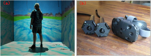
Figure 1. (a) Virtual reality; (b) Virtual globes; (c) VR globes (global scale) (d) VR globes (local scale).
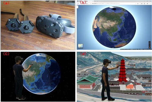
shows the concepts and relationships of virtual reality, virtual globes and VR globes. As shown in (a), virtual reality, generally refers to head-mounted virtual reality (Cordeil et al. Citation2017). It simulates a variety of human perception functions including visual, auditory and tactile by interactive devices such as head-mounted displays and hand controllers, which can make users fully immerse themselves in the virtual world (Skarbez, Frederick, and Whitton Citation2018; Hruby, Ressl, and de la Borbolla Del Valle Citation2019). As shown in (b), virtual globes, represented by Google Earth, is the new generation of 3D-GIS systems, which can realize the unified management and visualization of global spatial data by the simulating of the earth (Cozzi and Ring Citation2011). VR globes, a combination of virtual reality and virtual globes (Käser, Parker, and Bühlmann Citation2016; Käser et al. Citation2017; Huang and Chen Citation2019), makes user can interaction with global spatial data via natural behavior ( (c-d))).
Virtual reality can generate the immersive feeling of being personally on the scene (Skarbez, Frederick, and Whitton Citation2018; Hruby, Ressl, and de la Borbolla Del Valle Citation2019), which is mainly because it adopts a scene rendering mechanism based on binocular vision (Kaehler and Bradski Citation2016). As shown in , this mechanism must open two cameras to observe the scene at the same time, form the binocular images with parallax by means of controlling the relative distance of two cameras, and eventually achieve the stereoscope effect of a 3D scene according to the binocular image.
Figure 2. (a) The left and right cameras observe the scene to generate the binocular image with parallax; (b) Achieving the stereoscope effect of a 3D scene based on the binocular image.
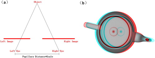
The relative distance of two cameras iswhere PupillaryDistance is a fixed value and Scale is the roaming scale (namely, the size ratio between the users in the virtual space and the users in the realistic space). The larger this value, the wider the observation range of user (Huang and Chen Citation2019).
This special rendering mechanism of VR requires that the 3D scene be continuously drawn twice within one frame. Because the scene complexity of VR globes, especially 3D city scenes that contain large numbers of fine building models, is much higher than that of normal visualization systems (Huang and Chen Citation2018), there is no doubt that direct binocular rendering will cause a serious reduction in the rendering efficiency and further affect the usability of system.
In addition, because the positions of the left and right cameras differ, the distance from the same object to the left and right cameras (range of visibility) will also be different. Existing virtual globes or VR globes generally achieves the global 3D scene multiresolution rendering through the tile quad-tree data model (Cozzi and Ring Citation2011), which makes the scene resolution significantly change as the range of visibility varies. Under the VR binocular rendering mechanism, the situation illustrated in can easily appear: the same region (in the circle) is expressed with tile of different resolutions in the left and right cameras; when the geometric or texture difference of tiles with different resolutions is relatively large, there will be the problem of erroneous binocular stereo matching, which greatly affects the vision experience of users.
Figure 3. The VR globe scene of some regions is expressed with tiles of different resolutions in the left and right cameras.
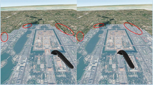
As shown in , the global image topographic scene in VR globes is constructed based on the tile quad-tree data model, and the data model make the VR globe scene of some regions is expressed with topographic tiles of different resolutions in the left and right cameras, when the difference in color tone of the topographic tiles of different resolutions is larger. The erroneous binocular stereo matching will occur.
In summary, how to achieve efficient rendering of global spatial data under the binocular rendering mechanism of VR and simultaneously ensure the consistency of the scene resolution observed by the left and right cameras are the two key questions to be resolved by VR globes. Therefore, in this paper, we propose a binocular parallel rending method for VR globes. This method mainly includes two parts. First, for the first problem, we design a binocular parallel rending model in this paper. This model assigns the rendering tasks of the left and right cameras to different central processing unit (CPU) cores to process via optimizing the rendering process and thus achieves parallel rendering of binocular scenes. Second, for the second problem, we propose a binocular scene resolution synchronize algorithm based on the binocular parallel rending model. Due to the organizational characteristics for the tile quad-tree data model, this algorithm conducts real-time synchronization on the resolution of the scenes observed by the left and right cameras in the rendering process and therefore avoids the problem of erroneous binocular stereo matching.
2. Related work
Parallel rendering is one of the approaches for rendering efficiency optimization that is mostly widely applied at present, and it mainly has two classes, the data-parallel and graphics-pipeline-parallel methods.
2.1. Data-parallel method
In the data-parallel method, the complicated scene loading process and image rendering process are performed in parallel, and the applications of this method in the existing 3D GIS field are very broad. For example, when existing virtual globes and VR globes draws a large-scale topographic scene, the loading process of topographic nodes and graph rendering process are processed in parallel, thus achieving the effect of simultaneous drawing and updating for the global topographic scene (Cozzi and Ring Citation2011). Huang applied this method to a 3D city scene and achieved the effect of simultaneous updating and rendering for the massive city buildings (Huang and Chen Citation2018). When She and Zhou et al. draw the polylines and polygon on terrain surfaces, the complicated polylines and polygon generation process and rendering process are implemented in parallel, and therefore, the final rendering frame rate is effectively improved (She et al. Citation2017). However, the aforementioned methods essentially only optimize the scene loading process. When it is applied to the VR environment, the rendering work of the left and right cameras is still concentrated on the serial implementation in a single thread, and it does not fundamentally solve the problem of the relatively low efficiency of VR binocular rendering.
2.2. Graphics-pipeline-parallel method
The graphics-pipeline-parallel method conducts the scene rendering while constructing multiple graphics pipelines. The so-called graphics pipeline is the process of transforming a scene from the geometric primitive to the frame image, and it mainly includes three major procedures: scene selection, sending draw calls, and rasterization. The graphics-pipeline-parallel method can also be further divided into parallel rendering based on the screen space and parallel rendering based on the model space (Molnar et al. Citation1994).
Parallel rending method based on the screen space
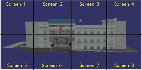
The parallel rending based on the screen space is also called the sort-first method. It achieves the decomposition of rendering tasks by cutting the screen (Moloney et al. Citation2011). As shown in , the entire screen is cut into eight parts that are not overlapping. Every part is allocated to different graphics pipelines that are responsible for rendering. Finally, the generated frame images are attached to obtain the final rendering result. Therefore, the sort-first method is very suitable for optimization of the rendering efficiency for visualization systems (such as tilled display walls) with multiple screens or cameras (Lai et al. Citation2015; Kido et al. Citation2016).
Figure 4. Tiled display walls.
The sort-first method also has relatively mature applications in VR. As shown in (a), CAVE (cave automatic virtual environments) is essentially one type of VR system based on tiled display walls (Muhanna Citation2015). It constructs an immersion-type virtual scene by surrounding the user with multiple display screens. Because the content displayed by each screen is independent of each other, we can allocate the rendering task of every screen to different computers that are responsible for executing and eventually achieve the frame alignment of multiple screens through the network protocol (Avveduto et al. Citation2016).
Figure 5. (a) Cave automatic virtual environments; (b) Head-mounted VR systems.
However, because CAVE has the problems of an expensive device and large size, it limits its promotion and development. The VR system that is currently often used is mainly the head-mounted VR shown in (b); HTC-VIVE, Oculus, and PSVR are VR systems that simulate binocular vision through head-mounted displays (Cordeil et al. Citation2017). In comparison with the surrounding screen of CAVE, the head-mounted display only has two screens corresponding to the left and right eye of human. However, because there is crossover in the field of vision for the left and right eyes, there is also overlap in the content displayed on the two screens (Kaehler and Bradski Citation2016). However, the existing sort-first method seldom considers the consistency problem of these overlapping regions. When it is directly applied, it is prone to cause the problem of erroneous stereo matching.
Parallel rendering method based on the model space
The method for parallel rendering based on the model space is also called the sort-last method. It achieves the decomposition of the rendering task by cutting the scene (Fang et al. Citation2010). If there are two objects, A and B, in the scene, they will be allocated to different graphics pipelines for the rendering, and finally, the generated frame images are merged to obtain the final rendering result. In comparison with the sort-first method, the main difficulty for the research regarding sort-last method is how to rapidly merge the finally generated frame images (Biedert et al. Citation2017). At present, there are mainly three classes: direct-send (Eilemann and Pajarola Citation2007), binary-swap (Ma et al. Citation1994), and radix-k (Kendall et al. Citation2010). However, these methods all require that the 3D scenes are organized in advance according to the unified data structure. In contrast, the scene organization manner of VR globes is more complicated. For instance, the topography adopts the organization of a tile quad-tree data model (Cozzi and Ring Citation2011), the urban building adopts the single LOD model organization (Huang and Chen Citation2018), and the vectors adopt the point, line, and plane organization (She et al. Citation2017). This type of multisource heterogeneous data organization characteristics restricts the application of sort-last method in VR globes.
Moreover, the concrete realization manner of the parallel rendering algorithm is also the content to be studied, and the existing methods essentially all achieve parallel rendering by building clusters (Avveduto et al. Citation2016). Because the head-mounted VR system is generally operated in the single-machine environment, if we build the special clusters only to improve the efficiency, there is no doubt that it will greatly increase the application cost of the system.
In summary, the parallel rendering method based on the screen space, namely, the sort-first method, is the most suitable parallel rendering method for VR globes at present, but the existing sort-first method is generally applied to tiled display walls and CAVE, as visualization systems whose screen space is not overlapping. Therefore, the design does not consider the consistency problem associated with overlapping scenes. When it is directly applied to the main VR system (head-mounted VR system) at present, the problem of erroneous binocular stereo matching can easily occur. In addition, the existing methods mostly achieve parallel rendering through the manner of constructing clusters. Because the head-mounted VR system is generally operated in the single-machine environment, how to achieve the binocular parallel rendering in the single-machine environment is also a focus of this paper.
The subsequent chapters of this paper are arranged as follows. Section 3 presents the Methodology. In particular, section 3.1 introduces how to decompose the rendering work of VR globes and assign the rendering tasks of the left and right cameras to different CPU cores to process, thus achieving parallel rendering of the binocular scene. Section 3.2 describes how to achieve real-time resolution synchronization of binocular scenes in the binocular parallel rendering process and therefore avoid the problem of erroneous binocular stereo matching. Section 4 is the experimental part, which is used to validate the effectiveness of method in this paper, and section 5 presents the conclusions and prospects for future work.
3. Methodology
3.1. Binocular parallel rendering model
To achieve the binocular parallel rendering of VR globes, we must first decompose the entire rendering work to determine which rendering procedures can be executed in parallel. Therefore, in this paper, we decompose the entire rendering work of VR globes into seven major procedures: camera movement, scene update, scene optimization, scene rendering, scene loading, texture preservation, and binocular display.
Camera movement: update the observation location and orientation of the left and right cameras.
Scene update: determine which objects (scene node) in the scene can be directly drawn, which must be loaded, and which must be deleted (which is generally realized by frustum culling).
Scene optimization: optimize the rendering content of scenes. For example, adjust the rendering sequence of scene nodes (Käser et al. Citation2017) and ensure that the scene nodes of the same rendering state can be drawn together, therefore effectively reducing the number of draw calls. This procedure is executed after scene update, and it can be neglected in general situations.
Scene rendering: transform the scene nodes that need rendering to the draw call and send to the graphics processing unit (GPU) for the rendering. This procedure is generally executed after scene optimization or scene update.
Scene loading: load the data from the external memory, and construct the scene nodes used for rendering (such as the building model and topographic tiles).
Texture preservation: through the RTT (render to texture) technique, the frame images generated by rendering are saved in texture form, which is convenient for subsequent association with the VR device. This procedure is mainly completed by the GPU.
Binocular display: call the interface of VR device and transfer the frame image (saved in texture form) to display on the screen of the VR device.
In particular, the three procedures of scene update->scene optimization->scene rendering are the core procedures of graphics pipeline. In this paper, we refer to the design idea of sort-first method and separate the procedures of graphics pipeline for the left and right cameras of the VR device. The final designed binocular parallel rendering model is shown in :
Figure 6. VR globes-oriented binocular parallel rendering model.
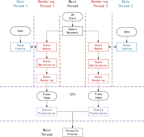
As shown in , the rendering work of the entire VR globes begins with camera movement and finishes with binocular display. When the execution of the camera movement procedure is completed, the two rendering threads are immediately opened to execute the graphics pipeline procedures (scene update->scene optimization->scene rendering). Meanwhile, the texture preservation procedure is implemented through GPU. Finally, call the interface of VR device, and send the saved texture image to the VR screen for the binocular display.
Moreover, to avoid the influence of the complicated scene dispatch and construction process on the rendering frame rate, we refer to the design idea of the data-parallel method and specially allocate a data thread for the left and right cameras to execute the scene loading procedure. Moreover, the constructed scene nodes are added to the scene to be drawn through the scene update procedure.
In addition to the design above, in the concrete implementation, to achieve binocular parallel rendering in the single-machine environment, we also conduct the following work.
We take p-buffers as the rendering target of the rendering thread: p-buffers can be considered as an invisible virtual window, and they are often used to achieve off-screen rendering. Because the rendering context of every p-buffer is independent of the others, we take p-buffers as the rendering target, which can ensure that two threads do not affect each other upon parallel rendering.
We adopt the barrier technique to synchronize the rendering thread: barrier is one of the basic techniques of multithread programing. It is often used to achieve simultaneous clogging and opening of different threads, and it achieves the goal of synchronous operation for different threads. Therefore, in this paper, we conduct synchronization of rendering threads before scene update and after scene rendering through this technique to avoid the problem of asynchronous frames. Moreover, if we adopt the double buffer mechanism, before and after sending draw calls to swap buffer, we must also conduct a synchronization of rendering thread.
Generally, to improve the rendering efficiency of VR globes, in this paper, we allocate the rendering work of the entire VR globes to be completed in parallel by five threads (one main thread, two rendering threads, and two data threads) and meanwhile adopt two parallel rendering methods, graphics-pipeline-parallel (sort-first method) and data-parallel. In the concrete implementation, we ensure that the rendering tasks of the left and right cameras are independent of each other through the p-buffers technique and achieve frame synchronization of the binocular rendering through the barrier technique.
3.2. Binocular scene resolution synchronization algorithm
Through the binocular parallel rendering model in section 3.1, we achieve binocular parallel rendering of VR globes. Although this parallel rendering manner can effectively improve the rendering efficiency of VR globes, it does not resolve the problem of inconsistent binocular scene resolution caused by the different viewpoint positions for the left and right cameras of VR. Therefore, it is necessary to design a binocular scene resolution synchronization algorithm on the basis of the binocular rendering model.
Tile quad-tree scene resolution synchronization algorithm
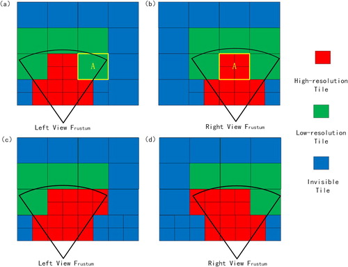
Because virtual globes and VR globes organizes the global multiscale spatial data mainly based on the tile quad-tree data model (Cozzi and Ring Citation2011), the key to solve the problem of synchronous binocular scene resolution in VR globes is how to conduct resolution synchronization on the tile quad-tree scene. As shown in , the tile quad-tree scene achieves the change of scene resolution by splitting or aggregating tiles. For instance, for tile A in the left camera, because it is closer to the right camera, it is split in the right camera. At this time, to ensure the consistency of the binocular scene resolution, it has to force tile A in the left camera to also split or force the subtiles of tile A in the right camera to be aggregated.
Figure 7. (a) Tile quad-tree scene observed by the left camera; (b) tile quad-tree scene observed by the right camera; (c) tile quad-tree scene observed by the left camera after the synchronization; and (d) tile quad-tree scene observed by the right camera after the synchronization.
To achieve the above goal, due to the characteristics of tile quad-tree data model, we propose a binocular scene resolution synchronization algorithm. The design idea of this algorithm mainly includes three aspects:
To match the binocular parallel rendering model designed in section 3.1, the designed algorithm requires the support of parallel computation. That is, the process of scene resolution synchronization is independently executed by the left and right cameras, and the execution sequence of the camera will not affect the results of the synchronization.
To avoid missing vision, we unify to transform the low-resolution scene to the high-resolution scene to achieve the synchronization of resolution. As shown in , we split tile A in the left camera rather than aggregating the subtiles of tile A in the right camera.
Because the tiles that require synchronous processing must belong to the set of tiles visible to two cameras, when one camera conducts the synchronous processing, the synchronization result must be directly used by the other camera to avoid repeated computation.
The detailed process of the algorithm is shown in algorithm 1:
By combining with algorithm 1, we can see that to satisfy the first design idea, the entire algorithm is essentially a traversing, sorting, and collection processes of tile quad-tree. Therefore, it can be placed in the scene update procedure of either camera. When the left and right cameras need to visit the same tile, we ensure the safety of thread by means of adding a mutex lock.
To satisfy the second design idea, we add a boolean variable Splited for every tile to identify the splitting state of tile. Once this value is set to be true, for the subsequent camera processing, it will be forced to split regardless of whether it satisfies the splitting condition.
To satisfy the third design idea, we collect the tiles visible to individual cameras and the publicly visible tiles separately in this paper, namely, define a shared tile set SharedTileSet to specially collect the publicly visible tiles. Once a certain tile is determined as a publicly visible tile (namely, when the value of Count is 2), it is inserted into SharedTileSet. Eventually, the tiles of either camera to be drawn are the tiles in SharedTileSet plus the tiles in PrivateTileSet with Count value of 1. In particular, Count is the integer variable and is used to identify to how many cameras the tile is visible.
3D city scene resolution synchronization algorithm
We achieve the resolution synchronization of tile quad-tree scene through algorithm 1. However, the 3D city scene of virtual globes or VR globes generally adopts the mixed data model of tile quad-tree data model along with the LodModel to organize the multiresolution scene (Huang and Chen Citation2018), as shown in . This mixed data model achieves multiresolution rendering of single building through the LodModel and achieves hierarchical block management of multiple LodModels through the tile quad-tree data model. When we process this class of data, it often cannot meet the requirements only with algorithm 1. Therefore, in this paper, we supplement a resolution synchronization algorithm for the LodModel on the basis of algorithm 1.
Figure 8. Mixed data model: (a) achieve the hierarchical block management of massive LodModels through the tile quad-tree data model; (b) the LodModel is composed of multiple Models with different resolutions.
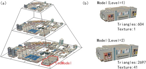
When we design this algorithm, algorithm 1 has placed all the publicly visible tiles (tiles after the synchronization) into SharedTileSet, and the LodModel that requires the resolution synchronization must be included in these publicly visible tiles. Therefore, only if we let the left and right cameras traverse the tiles in SharedTileSet, then take out the LodModel in these tiles and set the same rendering level for these LodModels, can we achieve the model resolution synchronization of 3D city scene.
In addition, through the preconditioning of algorithm 1, the total number of LodModels to be synchronized is also essentially determined. Therefore, we can adopt a simpler parallel computation strategy to match the binocular parallel rendering model designed in section 3.1: divide all the LodModels to be synchronized equally into two parts according to the quantity. The rendering thread of the left camera processes the first part, and the rendering thread of the right camera processes the second part. Because the data processed by two cameras are different, we do not need to consider the problem of thread safety. Meanwhile, the total amounts of data processed by two cameras are consistent, and therefore we also do not need to consider the load balancing problem.
The detailed algorithm is shown in algorithm 2:
Eventually, Model of either camera to be drawn is composed of three parts:
Model in PrivateTileSet collected according to the normal LOD selecting method.
Model in private model set PrivateModelSetLeft/PrivateModelSetRight collected through algorithm 2.
Model in shared model set SharedModelSet collected through algorithm 2.
In summary, we achieve binocular scene resolution synchronization of tile quad-tree scenes through algorithm 1. By supplementing algorithm 2 on the basis of algorithm 1, we achieve the binocular scene resolution synchronization of 3D city scenes (i.e. a mixed data model of tile quad-tree data model along with the LodModel). Because the vast majority of spatial data in the existing VR globes are organized based on the aforementioned data model, the binocular scene resolution synchronization algorithm proposed in this paper essentially can satisfy the application demands of VR globes.
4. Experiments and discussions
To validate the effectiveness of the method proposed in this paper, we conduct the experiment based on the open-source virtual globes platform osgEarth. In particular, the software environment is Windows 10 64-bit, OpenGL, OpenVR, and Visual Studio 2015. The hardware environment is an Intel(R) Core(TM) i7-8750H CPU, NVIDIA GeoForce GTX 1050Ti graphics card, 8 GB memory, and HTC-VIVE head-mounted VR system.
In the experimental data, the global image and topographic data adopt the TMS tile data service published by ReadMap. The data refer to the slice standard of tile map service in OGC to slice the data. That is, by staring from the top to the bottom on the globe, we conduct the quad-tree partition according to the manner of equal division of latitude and longitude, and it totally contains 1–13 levels of tile.
The urban building data adopt the 3D city model for certain region in Guizhou of China, and its slicing mode is consistent with the TMS tile data service. It contains a total of 12–17 levels of tile, and the single building in every tile contains three levels of LOD structure. The total data amount reaches 25 GB.
4.1. Binocular parallel rendering model
To verify that the binocular parallel rendering model designed in this paper can effectively increase the rendering efficiency of VR globes, in this paper, we take the global image topographic scene as the experimental subject. Under the situation without considering conducting the scene optimization, we compare the frame time needed for drawing different quantities of topographic tiles between the rendering model of existing virtual globes or VR globes (achieved on the basis of osgEarth rendering model) and the binocular parallel rendering model proposed in this paper. In particular, every topographic tile is composed of a grid with 17 × 17 vertices and texture with 256 × 256 pixels. The comparison results are shown in :
Figure 9. Frame time needed when two rendering models draw different amounts of topographic tiles.
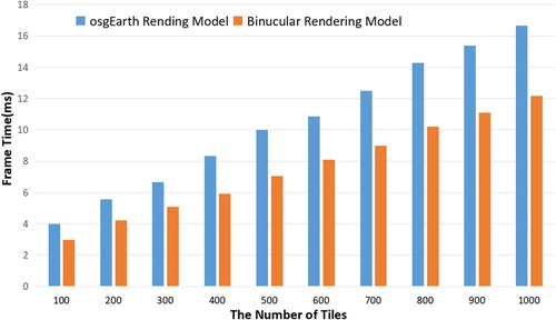
As shown in , compared with the existing rendering model, the binocular parallel rendering model proposed in this paper reduces the frame time by approximately 27% on average. Especially, as the scene complexity (i.e. number of topographic tiles) increases, the reduction degree is obvious. This is mainly because the existing rendering model generally only conducts the data loading process and graph rendering process in parallel (Cozzi and Ring Citation2011; Huang and Chen Citation2018); namely, it only considers the data-parallel approach. In comparison, the method in this paper not only considers the data-parallel approach but also follows the design concept of the sort-first method. It opens a graphics pipeline for the left and right cameras of VR for the rendering, and therefore it can better employ the parallel computation capability of multicore CPUs.
However, there is still a difference between the actual value when the frame time decreases by 27% and the ideal value when the frame time decreases by 50%. To analyze the reason, we list the time required by different rendering procedures (mainly the graphics pipeline procedure) for two rendering models while drawing 1000 topographic tiles in .
Table 1. Time taken (ms) of different rendering procedures for two rendering models.
In particular, scene update 1 and scene rendering 1 are the rendering procedures of the left camera, and scene update 2 and scene rendering 2 are the rendering procedures of the right camera. The effect after expressing the figures above in graphical form is shown in :
Figure 10. (a) Time taken for different rendering procedures for the osgEarth rendering model; (b) time taken for different rendering procedures for the binocular parallel rendering model.
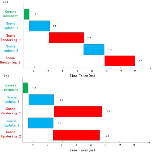
As shown in , for the existing rendering model, different rendering procedures are sequentially executed according to the serial manner, and therefore the final frame time is approximately equal to the accumulated value of time taken for different rendering procedures. The binocular parallel rendering model proposed in this paper executes the rendering procedure of different cameras in a parallel manner and decreases the final frame time. However, when it is specific to every rendering procedure (mainly the scene rendering procedure), the time taken for the parallel implementation is much higher than the time taken of serial implementation. For instance, the time taken of scene rendering 1 in the binocular parallel rendering model is 7.3 ms, whereas it is only 5.0 ms in the existing rendering model. This is most likely because the main task of scene rendering is to generate draw calls to the GPU. Because the entire system has only a GPU that is operating in the single-machine environment, when different CPU cores communicate with the same GPU, it is prone to cause blocking and eventually affects the parallel rendering effect.
It should be noted that only lists the time taken of camera movement, scene update 1, scene rendering 1, scene update 2 and scene rendering 2, so the total time taken of these rendering procedures is slightly lower than the frame time that is also affected by texture preservation, binocular display, scene loading and other rendering procedures.
In summary, the binocular parallel rendering model proposed in this paper cannot reduce the frame time by 50% (ideal value), but in comparison with the existing rendering model, its rendering efficiency is still obviously improved.
4.2. Binocular scene resolution synchronization algorithm
To verify that the binocular scene resolution synchronization algorithm (algorithm 1 and algorithm 2) designed in this paper can ensure that the left and right camera observes the global 3D scene with consistent scene resolution, in this paper, we use the global image topographic scene (constructed on the basis of tile quad-tree data model) and 3D city scene (constructed on the basis of mixed data model) as the experimental subject to compare the scene rendering effect before the synchronization and after the synchronization.
shows the effect of global image topographic scene before the synchronization and after the synchronization:
Figure 11. (a) Global image topographic scene before the synchronization and (b) global image topographic scene after the synchronization.
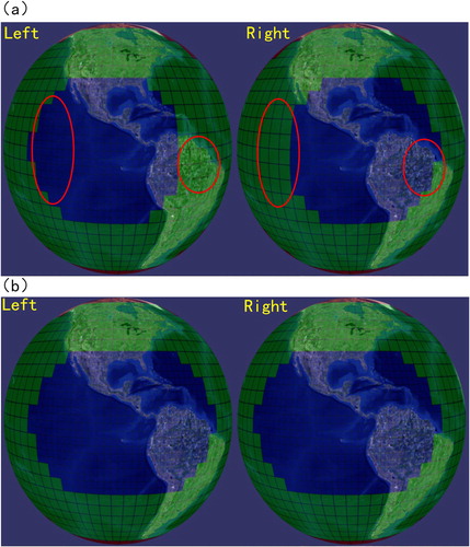
As shown in , to highlight the difference, we differentiate the topographic tiles of different resolutions with different colors in this paper. We can see that before the synchronization, because the viewpoints of the left and right cameras are different, the same region on the earth can be expressed with topographic tiles of different resolutions in the left and right cameras. After the synchronization, these regions are uniformly expressed by adopting the topographic tile with the highest resolution.
shows the effect of 3D city scene before the synchronization and after the synchronization:
Figure 12. (a) 3D city scene before the synchronization and (b) 3D city scene after the synchronization.
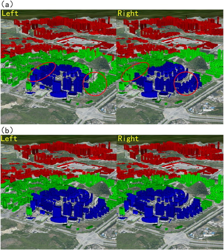
Similar to , to highlight the difference, in , we identify the different rendering levels of LodModel (single building) with different colors in this paper. We can see that, before the synchronization, the LodModel in the circle adopts different rendering levels in the left and right cameras for the rendering, whereas after the synchronization, the highest rendering level is uniformly used for the rendering.
Moreover, to verify that the synchronization calculation process of binocular scene resolution synchronization algorithms (algorithm 1 and algorithm 2) proposed in this paper will not cause significant influence on the rendering efficiency, in this paper, we compare the time taken of scene update procedure before and after the synchronization (according to section 3.2, we can see that the synchronization algorithm is conducted in the scene update procedure).
In particular, records the change in time taken for the scene update procedure before and after algorithm 1 is adopted to synchronize the global image topographic scene. In particular, we use the number of topographic tiles to express the change of scene complexity and the time taken of scene update takes the maximum time taken of left and right cameras. We can see that, when we draw 1000 topographic tiles, the enhancement of time taken for scene update caused by the synchronize algorithm is only 0.4 ms. However, according to , we can see that the frame time for rendering 1000 tiles is 12.1 ms, and therefore it essentially can be neglected.
Table 2. Comparison of time taken for the scene update procedure of global topographic scene before and after the synchronization.
records the change of time taken for the scene update procedure before and after algorithm 1 and algorithm 2 are adopted to synchronize the 3D city scene. In particular, we use the number of LodModels to express the variation in the scene complexity. Similar to , when we draw 5000 LodModels, the enhancement of time taken for scene update caused by the synchronize algorithm is only 0.9 ms, whereas the original time taken for the scene update procedure is 15.0 ms. Therefore, it can be essentially neglected.
Table 3. Comparison of time taken for the scene update procedure of 3D city scene before and after the synchronization.
In summary, the binocular scene resolution synchronization algorithms (algorithm 1, algorithm 2) proposed in this paper can effectively resolve the problem of inconsistent binocular scene resolution in VR globes, and the utilization of synchronization algorithm will also not cause significant influence on the overall rendering efficiency.
5. Conclusions and future work
To improve the rendering efficiency of VR globes, we propose a binocular parallel rendering method in this paper. This method includes two main parts: (1) a binocular parallel rendering model: this model improves the current rendering process of VR globes by assigning the rendering tasks for the left and right camera of VR to be processed on different central processing unit (CPU) cores, thereby achieving parallel rendering of binocular scenes. (2) a binocular scene resolution synchronization algorithm: this algorithm conducts real-time synchronization on the resolution of the scenes observed by the left and right cameras in the rendering process and therefore avoids the problem of erroneous binocular stereo matching. Compared with the existing method, the advantage of the method in this paper is mainly manifested in the following several aspects.
The current VR-GIS or VR globes system neglects the specificity of binocular rendering. The rendering work of different cameras is sequentially executed by adopting the serial manner, and it is difficult to ensure the efficiency. The method in this paper applies the parallel rendering technique to VR globes and allocates the rendering work of different cameras to different CPU cores by means of designing the binocular parallel rendering model. Moreover, it combines the techniques of P-Buffers and Barrier to achieve parallel rendering of VR globes under the single-machine environment. The experiment results indicate that the method in this paper can reduce the frame time of VR globes by approximately 27% on average.
The current VR-GIS or VR globes neglects the scene consistency problem in the binocular overlapped region. When there is complicated LOD structure in the scene, it is prone to cause the problem of erroneous binocular stereo matching due to the different binocular scene resolutions. Therefore, due to the characteristics of data model of VR globes, the method in this paper designs a synchronized algorithm to conduct a real-time adjustment on the resolution of global 3D scene observed by the left and right camera of VR, and ensure the consistency of binocular scene resolution. The experimental results indicate that the method in this paper can be effectively applied to the global image topographic scene and 3D city scene in the VR globe.
The method in this paper mainly solves the problems of relatively low efficiency and inconsistent binocular scene resolution for the virtual globe under the VR binocular rendering mechanism, and it establishes the foundation for the relevant techniques of VR globes visualization. The next step is to investigate how to combine the VR globe and specific geographic information applications. For example, the VR globe is applied to urban planning and construction, which makes the planners able to immediately feel the influence of the planning scheme on the urban environment by being personally in the scene after editing and modifying the urban scene and analyze the light conditions and traffic situation, thereby improving the working efficiency of urban planning.
Disclosure statement
No potential conflict of interest was reported by the authors.
Additional information
Funding
References
- Avveduto, Giovanni, Franco Tecchia, Marcello Carrozzino, and Massimo Bergamasco. 2016. “A Scalable Cluster-Rendering Architecture for Immersive Virtual Environments.” Paper presented at International Conference on Augmented Reality, Virtual Reality and Computer Graphics, Cham, Switzerland.
- Biedert, Tim, Kilian Werner, Bernd Hentschel, and Christoph Garth. 2017. “A Task-Based Parallel Rendering Component For Large-Scale Visualization Applications.” Paper presented at Eurographics Symposium on Parallel Graphics and Visualization, Lyon, France.
- Cordeil, M., T. Dwyer, K. Klein, B. Laha, K. Marriott, and B. H. Thomas. 2017. “Immersive Collaborative Analysis of Network Connectivity: CAVE-style or Head-Mounted Display?” IEEE Transactions on Visualization and Computer Graphics 23 (1): 441–450. doi:10.1109/TVCG.2016.2599107.
- Cozzi, Patrick, and Kevin Ring. 2011. 3D Engine Design for Virtual Globes. New York: A K Peters/CRC Press.
- Eilemann, Stefan, and Renato Pajarola. 2007. “Direct send Compositing for Parallel Sort-Last Rendering.” Paper presented at 7th Eurographics conference on Parallel Graphics and Visualization, Lugano, Switzerland.
- Fang, Wei, Guangzhong Sun, Peng Zheng, Tiening He, and Guoliang Chen. 2010. “Efficient Pipelining Parallel Methods for Image Compositing in Sort-Last Rendering.” Paper presented at IFIP International Conference on Network and Parallel Computing, Zhengzhou, China.
- Havenith, Hans-Balder, Philippe Cerfontaine, and Anne-Sophie Mreyen. 2019. “How Virtual Reality Can Help Visualise and Assess Geohazards.” International Journal of Digital Earth 12 (2): 173–189. doi:10.1080/17538947.2017.1365960.
- Hruby, Florian, Rainer Ressl, and Genghis de la Borbolla Del Valle. 2019. “Geovisualization with Immersive Virtual Environments in Theory and Practice.” International Journal of Digital Earth 12 (2): 123–136. doi:10.1080/17538947.2018.1501106.
- Hruby, F., A. Riedl, and H. Tomberger. 2008. “Virtual Representations of Antique Globes - New Ways of Touching the Untouchable.” International Journal of Digital Earth 1 (1): 107–118. doi:10.1080/17538940701782635.
- Huang, Wumeng, and Jing Chen. 2018. “A Virtual Globe-Based Time-Critical Adaptive Visualization Method for 3D City Models.” International Journal of Digital Earth 11 (9): 939–955. doi:10.1080/17538947.2017.1365958.
- Huang, Wumeng, and Jing Chen. 2019. “A Multi-Scale VR Navigation Method for VR Globes.” International Journal of Digital Earth 12 (2): 228–249. doi:10.1080/17538947.2018.1426646.
- Kaehler, Adrian, and Gary Bradski. 2016. Learning OpenCV 3: Computer Vision in C++ with the OpenCV Library. Sebastopol, CA: O'Reilly Media.
- Käser, Dominik, Evan Parker, and Matthias Bühlmann. 2016. “Bringing Google Earth to Virtual Reality.” Paper presented at ACM SIGGRAPH 2016 Talks, Anaheim, California.
- Käser, Dominik, Evan Parker, Adam Glazier, Mike Podwal, Matt Seegmiller, Chun-Po Wang, Per Karlsson, et al. 2017. “The Making of Google Earth VR.” Paper presented at ACM SIGGRAPH 2017 Talks, Los Angeles, California.
- Kendall, Wesley, Tom Peterka, Jian Huang, Han-Wei Shen, and Robert Ross. 2010. “Accelerating and Benchmarking Radix-k Image Compositing at Large Scale.” Paper presented at 10th Eurographics conference on Parallel Graphics and Visualization, Aire-la-Ville, Switzerland.
- Kido, Yoshiyuki, Kohei Ichikawa, Susumu Date, Yasuhiro Watashiba, Hirotake Abe, Hiroaki Yamanaka, Eiji Kawai, Haruo Takemura, and Shinji Shimojo. 2016. “SAGE-based Tiled Display Wall Enhanced with Dynamic Routing Functionality Triggered by User Interaction.” Future Generation Computer Systems 56: 303–314. doi:10.1016/j.future.2015.09.033.
- Lai, D., B. Sajadi, S. Jiang, Gopi Meenakshisundaram, and A. Majumder. 2015. “A Distributed Memory Hierarchy and Data Management for Interactive Scene Navigation and Modification on Tiled Display Walls.” IEEE Transactions on Visualization and Computer Graphics 21 (6): 714–729. doi:10.1109/TVCG.2015.2398439.
- Ma, Kwan-Liu, J. Painter, C. Hansen, and M. Krogh. 1994. “Parallel Volume Rendering Using Binary-Swap Compositing.” IEEE Computer Graphics and Applications 14 (4): 59–68. doi:10.1109/38.291532.
- Molnar, S., M. Cox, D. Ellsworth, and H. Fuchs. 1994. “A Sorting Classification of Parallel Rendering.” IEEE Computer Graphics and Applications 14 (4): 23–32. doi:10.1109/38.291528.
- Moloney, B., M. Ament, D. Weiskopf, and T. Moller. 2011. “Sort-First Parallel Volume Rendering.” IEEE Transactions on Visualization and Computer Graphics 17 (8): 1164–1177. doi:10.1109/TVCG.2010.116.
- Muhanna, Muhanna A. 2015. “Virtual Reality and the CAVE: Taxonomy, Interaction Challenges and Research Directions.” Journal of King Saud University - Computer and Information Sciences 27 (3): 344–361. doi:10.1016/j.jksuci.2014.03.023.
- She, Jiangfeng, Yang Zhou, Xin Tan, Xingong Li, and Xingchen Guo. 2017. “A Parallelized Screen-Based Method for Rendering Polylines and Polygons on Terrain Surfaces.” Computers & Geosciences 99: 19–27. doi:10.1016/j.cageo.2016.10.011.
- Skarbez, Richard, P. Brooks Frederick, and Mary C. Whitton. 2018. “A Survey of Presence and Related Concepts.” ACM Computing Surveys 50 (6): 1–39. doi:10.1145/3134301.