
ABSTRACT
There are different processes in 3D urban land administration in which spatial analysis plays an underpinning role. Among 3D data models, Industry Foundation Class (IFC) provides the potential capabilities for modelling legal and physical dimensions of urban properties. However, performing spatial analysis using IFC files cannot address the on-demand spatial analysis requirements of 3D urban land administration. In response to this limitation, 3D data needs to be stored in a spatial database to enable spatial analyses required by different stakeholders. Therefore, in this paper, by considering spatial analysis requirements in 3D-enabled urban land administration, an IFC-based database schema is designed. Moreover, a methodology for transforming Building Information Modelling (BIM) data into the proposed schema is provided. This methodology includes seven steps: designing the architectural model and adding legal data, georeferencing, IFC data validation and cleaning, mapping process, database data validation and cleaning, spatial analysis, and visualisation. To demonstrate the feasibility of the proposed database, three datasets are implemented in the database. Moreover, a new method for modelling legal spaces with oblique structures and two applications of spatial analysis in 3D urban land administration are provided.
1. Introduction
The significant trend of urbanisation and population growth is resulting in the rapid development of multi-story buildings and architecturally complex structures in cities. The spatial and functional complexity of urban environments challenges the current land administration systems that are responsible for ensuring the management of rights, restrictions, and responsibilities (RRRs), valuation and taxation, and planning and control of land use and natural resources (Enemark Citation2005). Urban land administration is defined as ‘the information and processes required to support subdivision, registration, and ongoing management of those complex RRRs characteristic of urban areas’ (Ho Citation2014).
Unambiguous communication and coordinated management of 3D digital data related to complex RRRs in urban areas are fundamental and beneficial for different processes in urban land administration. For instance, property valuation is one of the important processes which requires 3D geometrical (Isikdag et al. Citation2014, Citation2015), physical (e.g. area), fiscal (e.g. rental price), and environmental (e.g. view) data (Cagdas et al. Citation2016; Kara et al. Citation2018). In order to retrieve the required environmental information for property valuation, different spatial analyses are needed. These analyses include visibility analysis, solar potential analysis, flooding risk analysis, noise analysis, distance analysis (accessibility to key facilities), daylight, and sunlight analyses.
Another example of required spatial analysis in 3D urban land administration is related to property boundaries. Representation of property boundaries in a 3D environment leads to easier communication of rights, restrictions, and responsibilities (RRRs) information to the cadastral users and minimising disputes and risk of misinterpretation (Shin et al. Citation2020). In order to retrieve property boundaries from a 3D model, boundary identification analysis should be performed (Barzegar et al. Citation2019). In some jurisdictions, such as Victoria, Australia, some legal boundaries are assigned to the faces of building elements such as walls, ceilings, and floors. Therefore, for extracting the property boundaries, surface-level queries are needed.
Generally, for each 3D spatial analysis, a specific Level of Detail (LoD) is required. Using a model with an appropriate LoD plays a pivotal role in the duration of the processing and accuracy of the results since higher LoD leads to higher computation cost, and lower LoD leads to achieving less accurate results in many spatial analyses. For instance, considering Victorian land administration as an example, based on the regulations of City of Melbourne (city council), one of the analyses that should be checked in the process of land administration is overlooking. Based on regulations in Victoria, a habitable room window, balcony, terrace, deck or patio should be located and designed to avoid direct views into the private open space of an existing dwelling within a horizontal distance of 9 meters of the window, balcony, terrace, deck or patio. Views should be measured from a height of 1.7 metres above floor level and, within a 45 degree from the plane of window or perimeter of balcony, terrace, deck or patio (Department of Environment Land Water and Planning Citation2020). Therefore, for performing this analysis, at least LoD3 is needed since some of the required building elements including window, balcony, terrace, deck or patio are only accessible in LoD3.
In order to lay a foundation for designing a unified spatial analysis system for 3D urban land administration, the first step is considering a 3D data model that can model both physical and legal data. Currently, Building Information Modelling (BIM) is adopted by many countries for managing 3D physical dimension of buildings. Moreover, recent studies have shown that a BIM-based approach is a beneficial approach for managing 3D legal data in urban land administration (Barzegar et al. Citation2019; Rajabifard, Atazadeh, and Kalantari Citation2019; Atazadeh et al. Citation2017a, Citation2017b; Olfat et al. Citation2019; Atazadeh et al. Citation2019). Therefore, it is more probable that land surveyors would use BIM models for the purpose of subdividing the ownership of properties (Barzegar et al. Citation2019; Rajabifard, Atazadeh, and Kalantari Citation2019).
Due to this fact that architects use different BIM software, when it comes to sharing information, an open file format such as IFC should be chosen to guarantee software independency. However, by using IFC files, surface-level queries are not possible. This stems from the fact that building elements such as walls, ceilings, and floors are modelled as solids in IFC. However, extracting faces of solids from an IFC file is impossible since faces of solids are not considered as a separate object-type. Therefore, they do not have a specific GlobalId and cannot be extracted from the IFC file. Consequently, performing spatial analysis such as boundary identification which needs surface level queries is impossible. Moreover, each 3D spatial analysis needs a specific LoD; however, extracting a subset of the model based on the required LoD using IFC files needs additional tools. Furthermore, since the accessibility of data can be controlled only at the file level and different access privileges cannot be defined for users at the object-level, tracking the changes in histories of models is difficult. Noteworthy to mention that after registration of a property in the urban land administration system, the data should not be changed by stakeholders since the properties have been built in reality. However, in case of property destruction or renovation, the data can be only updated by land registry.
This study aims to use a 3D spatial database for solving the issues regarding IFC files. Due to differences between geometry of 3D data in IFC and a spatial database, in a spatial database, data can be accessed not only at the object-level but also at the surface level. Therefore, spatial analyses that consist of several object and surface-level queries are possible. Moreover, different access privileges can be defined on the object level or even surface level for different users. As a result, only specific users can edit or manipulate the data (Zhang et al. Citation2014). In addition, by considering the required LoDs in the design of the database, for each analysis, only the required subset of the model is extracted which leads to lower computation cost in performing 3D spatial analysis. Furthermore, since within an organisation, files are created by different programmers from various departments over long periods of time, and it can lead to data redundancy, using a spatial database eliminates data redundancy and data only needs to be stored once. Therefore, in this paper, an IFC-based spatial database for 3D urban land administration is developed to support the required spatial analysis in this domain.
2. Related work
The IFC is a standardised data model for managing and exchanging information related to the built environment during the design, construction, and operation processes (BuildingSMART Citation2020a). The studies which have investigated retrieving information from an IFC model are categorised into two categories. In the first category, the IFC file itself is used for retrieving the information. For instance, Zhang and El-Gohary (Citation2020) proposed a method for extending the IFC schema to include the necessary information for building value analysis such as noise level, fire rating, heat loss, solar gain coefficient. Moreover, they provided an algorithm for extracting the required information for value analysis using JAVA programming. This algorithm can only extract attribute information, not geometry information.
Some studies also developed a new query language for querying IFC data in a specific domain. (Daum and Borrmann Citation2014) developed QL4BIM query language to retrieve spatial information in the AEC industry domain from IFC data. The Building Information Model Query Language (BIMQL) proposed by Mazairac and Beetz (Citation2013) is another query language for retrieving information from an IFC file. This language cannot support spatial queries.
In the second category of studies, a database is used for retrieving information from an IFC model. However, when it comes to 3D spatial analysis and generating new geometries from existing geometries, few of these studies can support 3D spatial analysis. For instance, IMSvr (Hietanen Citation2002) stores IFC data in Microsoft SQL Server. However, the Microsoft SQL Server database is a relational database that can support a limited number of geometry types and cannot support complex 3D geometries of IFC. Therefore, performing 3D spatial analysis using this server is impossible.
BIMServer is the most popular IFC model server which provides an interface based on Java to construct a partial BIM model query and uses Oracle Berkeley DB as the backend database (Ying, Lee, and Lu Citation2016). BIMServer does not have any 3D spatial operator for doing spatial analysis, and it can only be used for performing attribute queries. In one study, BIMServer has been used for querying cadastral information, including legal space and boundaries from an IFC model using JSON (JavaScript Object Notation) queries (Atazadeh et al. Citation2019).
Among 3D spatial databases, PostGIS extension to PostgreSQL and Oracle Spatial and Graph are the most popular databases which can support 3D spatial analysis. Several studies used these two databases for storing IFC data. For instance, Solihin et al. (Citation2017) defined schema and transformation rules to bring IFC data into the Oracle database based on the requirements of the AEC industry. Li et al. (Citation2016) also stored IFC data in the Oracle database. In this process, they considered all the entities and relationships of IFC data. In another study, (Lee et al. Citation2014) stored IFC data in the CUBRID database (CUBRID Citation2020), based on both an object-relational approach and a relational approach and compared their performance. They found that using an object-relational approach leads to better query performance. They also considered all IFC entities in the mapping process.
To sum up, most of the studies which have used the IFC model itself for retrieving information can only support the required queries in a specific domain. Moreover, BIMQL, which is a general query language, cannot support spatial queries. Furthermore, sometimes various access privileges are needed; however, accessibility of data can be controlled only at the file level.
In case of studies that used a database for retrieving information, most of the current IFC-based databases do not support 3D spatial analysis. Moreover, most of the studies which used spatial databases focused on storing IFC data with its original data structure. However, a 1-to-1 mapping requires a plethora of tables, which decreases the functionality of the database in response to complicated spatial queries and increases the execution time. Furthermore, generally, users only need the final geometry, and they are not interested to know how geometry is constructed. Therefore, abstract and semantic IFC entities such as IfcRoot, IfcPropertyDefinition, IfcObjectDefinition, and so on are not necessary to be defined as separate tables in the database (Solihin et al. Citation2017). Although Solihin et al. (Citation2017) designed a database schema based on the requirements of the AEC industry domain, they did not consider legal aspects in their designed database. Furthermore, some of the considered physical objects and attributes in their proposed schema are redundant, and there is no need to store these elements in a 3D urban land administration database. Therefore, this database cannot answer the spatial analysis requirements of 3D urban land administration
In order to overcome these problems, this paper provides an IFC based database schema based on the requirements of 3D urban land administration. This database considers both physical and legal aspects to support the required attribute and spatial queries in this domain. Based on the previous investigations related to spatial analysis in 3D urban land administration, this database must provide capabilities for checking 3D topological relationships between physical and legal objects and also retrieving the result of 3D intersection (Barzegar et al. Citation2019; Yu et al. Citation2017; Sucaya and Ary Citation2009; Atazadeh et al. Citation2017c).
3. Spatial analysis requirements in the Victorian land administration system
Preliminarily to designing a database schema for spatial analysis in urban land administration, it is necessary to consider existing regulations, legislation and jurisdictional aspects to identify spatial analysis requirements. However, since the regulations of each jurisdiction are different from another jurisdiction, in this research, the Victorian land administration system is considered as a case study. Based on the land management paradigm proposed by Enemark (Citation2005), land administration system has four functions including land tenure, land value, land use and land development. In Victoria, the key stakeholders for land tenure function are Land Use Victoria (land registry) and Strata Community Association (Owners Corporation). Moreover, for land value function, the key stakeholder is Valuer-General Victoria, and for land use and land development functions, the key stakeholder is the City of Melbourne (city council). By considering the regulations of the identified stakeholders, the required LoD for each analysis is extracted based on CityGML's classification (Gröger and Plümer Citation2012) ().
Table 1. The required spatial analysis in the Victorian land administration system.
4. IFC-based database schema
In order to overcome the limitations of using IFC files for retrieving information and support the spatial analysis requirements in 3D urban land administration, an IFC-based database schema is designed. As mentioned before, for designing the BIM models, architects may use different BIM software. However, some of the BIM software such as SketchUp Pro do not support the new version of IFC (IFC4) (SketchUp Citation2021). Therefore, IFC 2×3, which is supported by all BIM software is considered in this study. The first step in designing the database schema is identifying the relevant IFC elements to urban land administration. According to (Atazadeh Citation2017), the relevant IFC elements to land administration can be classified into four main categories, including spatial elements, physical elements, actor elements, and elements for referencing documents. Since the first three categories are fundamental elements for spatial analysis, and the last category is only text information, the focus of this paper is on spatial, physical, and actor elements. and show these elements.
Figure 1. Relevant spatial and physical elements in IFC schema (Atazadeh Citation2017).

Figure 2. Relevant actor elements in IFC schema (Atazadeh Citation2017).
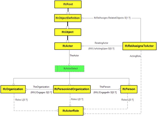
Some of the elements in and , such as IfcRoot and IfcObjectDefinition, are abstract and semantic elements and do not have a geometry. As mentioned before, generally, users only need the final geometry, and they are not interested to know how geometry is constructed. Therefore, abstract and semantic IFC entities are not necessary to be defined as separate tables in the database.
Spatial elements are used for modelling spatial structures, which can be defined in either a non-hierarchical way such as IfcSpatialZone or a hierarchical way such as IfcSite and IfcSpace. Generally, IfcSpatialStructureElement is the abstract superclass for defining spatial elements including site (IfcSite), building (IfcBuilding), building storey (IfcBuildingStorey) and internal space (IfcSpace) objects, and IfcExternalSpatialStructureElement is used for defining external regions and airspaces around the building (BuildingSMART Citation2020b).
Physical elements include building elements such as IfcWall and IfcWindow, distribution elements (IfcDistributionElement) for representing utility networks, and geographic and civil elements (IfcGeographicElement and IfcCivilElement) for representing geospatial features such as roads, bridges, pavements, and trees. The related tables to these IFC entities are provided in .
Table 2. Entity_types in the proposed database schema (Entity_types table includes only EntityType_ID, EntityType_name and LoD columns in database. Concepts with * sign have been customised based on the identified analytical requirements in ).
The second type of IFC elements pertinent to urban land administration is actor elements. Actor elements define actors involved in the development process of a building project, which can be a person or organisation. Actor elements can be used for defining the owner of each property. However, due to limitations in the mapping process between different data formats, which will be discussed in the mapping subsection, instead of IfcPerson and IfcOrganisation, the IfcOccupant element which is one of the sub-elements of IfcActor element is used for defining owners.
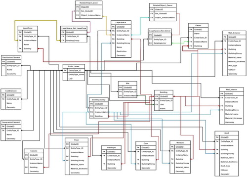
shows the designed IFC-based database schema for 3D urban land administration. Generally, for doing spatial analysis, different Level of Details (LoDs) are required. These LoDs are defined based on CityGML's classification and the requirements of spatial analysis in . In addition, in the designed schema, in the Entity-types table, an ID is assigned to each Entity_type (E.g. Building, Slab, Roof. etc.) and the lowest LoD in which this entity type can be represented is defined. shows the relation between the Enitity_types in the database with IFC elements and architectural concepts in BIM models. Moreover, it shows the equivalent IFC entities in BIM models (Autodesk Citation2018; Valez Citation2018).
Figure 3. The IFC-based database schema for urban land administration.
Noteworthy to mention that although in BIM some concepts such as Level of Development (Latiffi et al. Citation2015) and Level of Information Need (UK) (UK BIM Alliance Citation2019) exist; however, these concepts are used for sharing information among partners of a BIM project during its life-cycle. Therefore, they have not been defined by considering spatial analysis requirements in GIS, and they are not well known among spatial analysts. Considering the Level of Detail concept of GIS in this research helps to provide the opportunity of retrieving elements from the database based on the analytical requirements of each spatial analysis. Therefore, performing the mapping process from IFC to CityGML and then from CityGML to database can be avoided since each data conversion may lead to data loss or errors and increasing the cost of the process.
Furthermore, it should be considered that the geometry of IFC is different from CityGML. For instance, a wall in IFC is a 3D object, but in CityGML it is represented as interior and exterior wall surfaces. Subsequently, in LoD 2 of CityGML, only the exterior walls should be considered; however, due to the surface-based geometry of CityGML, only the exterior shell of walls is considered. By applying LoD2 concept in the BIM environment and keeping in mind that in BIM, walls are not surface-based geometries, only exterior walls should be considered for the spatial analyses that require LoD2. Although in IFC walls are modelled as solids, in the database they are modelled using polyhedral surface geometry. Therefore, even if the analyst needs to extract the faces of walls, it can be done effortlessly using the spatial operators of the database.
Since some elements such as IfcBuilding and IfcBuildingStorey are defined as semantic elements and do not have a geometry, there is no need to define an LoD for these elements. Moreover, two relations, including Ifc_is_contained_in and Ifc_decomposes are defined using BuildingStorey attribute for all entities, and they are not defined in separate tables since they refer to the building storey in which the element is located. When it comes to defining building storey for each IfcSpace, the related relation, which refers to the building storey that IfcSpace is located is Ifc_decomposes, but for other entity types such as wall and window, this relation is Ifc_is_contained_in.
Noteworthy to mentions that, some of the concepts in BIM have been customised based on the identified analytical requirements in . For instance, for performing outdoor analysis, only the walls that create the outer surface of the building are needed. Based on the definition of IfcCurtianWall, this entity type is used for defining the walls located outside of the building and enclosing it. However, in case of IfcWall and IfcWallStandardCase, both wall types are used for defining interior and exterior walls (BuildingSMART Citation2020b). Therefore, in order to be able to filter only exterior walls, all walls which create the outer surface of buildings in BIM models are exported as IfcWall and IfcCurtainWall and stored in the Wall_Exterior table, and they are differentiable using the Wall_type attribute in the Wall_Exterior table. Moreover, IfcWallStandardCase is only used for internal walls and is stored in the Wall_Interior table in the database. More details regarding defining IFC types for walls in a BIM model will be provided in the first subsection of methodology.
The same strategy can be used for horizontal structures such as floors, floor slabs, roofs, ceilings and roof slabs. In BIM models, the roof is the topmost layer of a building, the roof slab is usually a concrete structure below the roof, and the ceiling is located below the slab. However, roofs usually are defined for houses, and in some multi-storey buildings such as Figure 10, even for defining the topmost layer, ceiling element is used. Although in this case, the ceiling has two roles (roof and ceiling) and for spatial analyses that require LoD2 only roof should be considered and not the ceilings inside of the building, generally, the number of ceilings in one building is not numerous and it does not increase the computation cost in the analysis. Therefore, IfcRoof and IfcCovering (ceiling) elements can be stored in the Roof table for those spatial analyses that need LoD2 and differentiated by Roof_type attribute.
Furthermore, in BIM models, the floor is the surface that we can stand on it and the slab floor is usually a concrete structure below the floor. IfcSlab is used for defining both floor slab and roof slab. However, for outdoor analysis (LoD2), only roof slab is needed since in some buildings architects only define roof slab without defining roof on top. Therefore, IfcSlab elements with IfcSlabTypeEnum property of Roof are also stored in the Roof table. Moreover, since there is no IFC element specifically for defining floors in IFC, both floor and floor slabs are defined as IfcSlab. Therefore, IfcSlab elements with IfcSlabTypeEnum property of Floor are stored in the Floor table.
In case of the IfcStairFlight element, this element refers to an uninterrupted series of stairs that are aggregated by the IfcStair element. Therefore, a group of stairs which are located in one building storey can be defined by an IfcStair element. In addition, Ifc_is_contained_in relation defines the relation between IfcBuildingStorey and IfcStair element. However, since IfcStair element is a semantic concept and does not have a geometry and it can be used only for defining building storey for IfcStairFlight element, there is no need to define a separate table for IfcStair element. Moreover, based on urban land administration requirements, information about the building in which IfcStairFlight elements are located is enough, and there is no need to store the information related to the building storey in which an IfcStairFlight is located.
In urban land administration, each legal space is associated with some rights, restrictions, and responsibilities. Generally, rights are related to ownership and tenure, restrictions control land use and activities, and responsibilities related to having a social, ethical commitment or attitude to guarantee environmental sustainability (Enemark Citation2009). In the proposed schema, rights are defined by the IfcOccupant entity (Owner table), which relates to its associated IfcSpace (LegalSpace table) by IfcRelOccupiesSpaces relationship (LegalSpace_Rel_Owner table). Moreover, restrictions are defined by defining the Restriction attribute for each legal space in the LegalSpace table. Since responsibilities are derived based on rights and restrictions and have implicit nature, there is no need to store them in the database. Generally, due to privacy policies, there is no information about owners of properties on subdivision plans. Therefore, access to the name of owners needs to be restricted in the database by defining some privileges for specific users who have the right to access to Owner table. In the IfcRelOccupiesSpaces relationship, RelatingActor shows the name of owner and RelatedObjects shows the associated legal spaces with this owner. Since each owner can have multiple legal spaces, the RelatedObjects column may have several values separated by comma. In order to guarantee normalisation in the database, another table (RelatedObject_Owner) is created to store the associated legal spaces with each owner. Consequently, each rows of this table only refers to one legal space and each value for RelatedObjects component is stored as Object_InstanceName attribute in RelatedObject_Owner table.
Furthermore, each ownership arrangement may include several legal spaces that are defined by IfcZone (LegalZone table). For instance, an IfcZone can include a lot, a storage area, and a car park that have the same ownership. The IfcRelAssignsToGroup entity (LegalSpace_Rel_LegalZone table) defines the relationship between IfcSpace (LegalSpace table) and IfcZone (LegalZone table) entities by two attributes, including the RelatingGroup, which refers to IfcZone and the RelatedObjects, which references a set of IfcSpace instances within the zone. To guarantee normalisation in the database, another table (RelatedObject_Zone) is created to store the associated legal spaces with each zone. Consequently, each rows of this table only refers to one legal space and each value for RelatedObjects component is stored as Object_InstanceName attribute in RelatedObject_Zone table.
5. Methodology to transform IFC data into the proposed schema
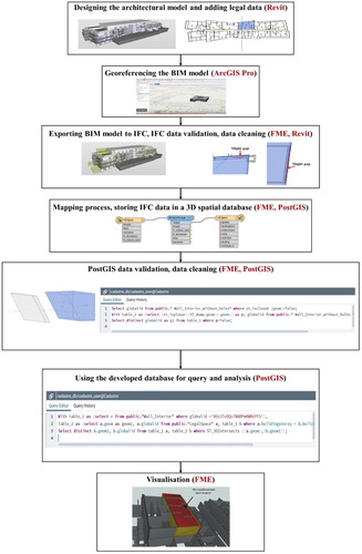
After designing the database schema, a database should be chosen to store the data based on the designed schema. As mentioned before, among 3D spatial databases, PostGIS extension to PostgreSQL and Oracle Spatial and Graph are the most popular databases which can support 3D spatial analysis. Both Oracle Spatial and PostGIS databases do not fully support 3D topological relationships. The most important topological relationship is the 3D intersection, and by adding extra rules to the 3D intersection, other topological relationships can be detected. However, Oracle can only detect the intersection between two objects (Boolean result) and cannot retrieve the result of a 3D intersection (Oracle). Therefore, PostGIS is a better option for supporting spatial analysis requirements for 3D urban land administration since not only it can detect the 3D intersection between two objects, but also it can retrieve the result of 3D intersection (PostGIS). Moreover, PostGIS is totally free, and (Shukla, Chirag Shivnani, and Shah Citation2016) also showed that PostGIS outperforms Oracle Spatial in spatial analysis. Therefore, in this study, by considering PostGIS as the database, a methodology for storing data in the database and performing spatial analysis is developed (). This methodology is constituted of seven steps. The details of each step are explained in the following subsections.
Figure 4. The required steps to transform 3D data to PostGIS database for performing spatial analysis.
5.1. Designing the architectural model and adding legal data
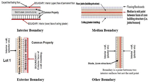
In order to prepare data for land administration, the architectural model, which includes physical data is designed by the architect. Then, the information related to RRRs needs to be added to physical data in Revit. In case of legal boundaries, generally, there are four different types of legal boundaries in the cadastral system of Victoria, including Interior, Exterior, Median, and Other boundaries. shows these types of boundaries. An ‘Interior’ boundary for a horizontal building object such as a ceiling or floor is defined by the lower and upper faces of an object, and for a vertical building object such as a wall is defined by the interior face of the building object. The ‘Exterior’ boundary is defined just for vertical building objects and is defined based on the exterior face of the building. A ‘Median’ boundary is defined based on the midline between faces of a horizontal or vertical building object. The ‘Other’ boundary is defined based on a line (except midline) between two interior faces of a vertical or horizontal building object (Barzegar et al. Citation2019).
Figure 5. Different types of boundaries in the cadastral system of Victoria (Land Use Victoria Citation2015).
To define ownership boundaries and create legal spaces, a method proposed by (Atazadeh et al. Citation2017a) has been used. In this method, ‘Interior’ boundaries are defined by checking the Room bounding attribute of Revit and ‘Median’, ‘Exterior’ and ‘Other’ boundaries are modelled using the Room Separator tool. After defining boundaries, the 2D footprint of each legal space is automatically created by applying the Room tool in Revit. Noteworthy to mention that, for each property, the boundaries are defined as 2D lines in the Revit and together, they create the 2D footprint of the legal space. However, after exporting Room element (2D footprint of legal space) to IfcSpace (3D legal space), the Room is extruded based on the height of the building storey in which the Room is located (the resultant object can only have the extrusion geometry). Therefore, the 2D legal space is converted to the 3D legal space and 2D boundary lines are converted to 3D surfaces which are faces of the 3D legal space.
Although this method can perfectly model legal spaces with vertical walls (even with curved shape if the footprint of the uppermost and the lowermost of the wall are the same) and horizontal roofs, it cannot model legal spaces surrounded by complex building structures such as oblique walls and roofs. In case of oblique walls and their associated oblique boundaries (), the geometry of the uppermost section of the oblique wall is different from the lowermost. Therefore, oblique boundaries and their associated 3D legal space cannot be shown using the Room element in a BIM model.
Figure 6. Representation of oblique walls in 2D and 3D.
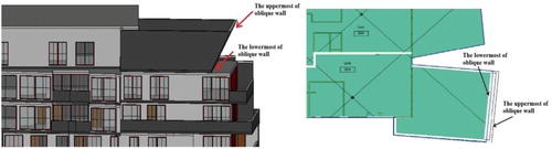
For drawing oblique walls and roofs and their associated 3D legal space, the Massing method in the Revit is used. Since masses are defined as 3D objects in the Revit software, they can be used for defining complex objects such as extrusions, lofts, sweeps, revolves and blends (Autodesk Citation2020). Therefore, considering a legal space with one oblique wall and roof as an example, first, the 2D footprint of the property is drawn. Then, this 2D footprint is extruded to create a 3D object (mass). By defining a slope aligned with one of the vertical sides of the mass, an oblique surface is created. Then this surface can be chosen as the exterior face (Exterior boundary) or interior face (Interior boundary) or a face located at the midline of the wall (Median boundary) and an oblique wall can be created. Since only Exterior, Interior and Median boundaries can be created automatically, after creating the oblique wall, in case of an Other boundary, the created sloped face of the mass should be shifted to locate it at the right place (the exact location of Other boundary). The same procedure can be used for an oblique roof; however, for the roof, the required slope should be defined for the topmost face of the mass.
Since oblique structures are a special kind of building structure, it is better to define them using a separate family type (Complex) for roof and wall in order to be able to identify them in the database. Moreover, by exporting masses from a BIM model to IFC as IfcSpace element, they can be stored in the LegalSpace table in the database as a legal space (as mentioned in ).
In the Revit software, new attributes can be defined for objects based on user requirements. However, not all user-defined attributes can be mapped to IFC. In order to be able to map an attribute to its equivalent in the IFC, the attribute should be defined under the category of IFC Parameters. Therefore, for defining the owner of each legal space, the Occupant attribute under the category of IFC Parameters is added for the Room and Mass elements which are representative of legal spaces. Although the occupant concept is different from the owner concept, the attributes which are defined under the category of IFC Parameters need to be defined by specific names that can have an equivalent in the IFC hierarchy. Therefore, after exporting IFC from Revit, these parameters can be detected as IFC Parameters. Based on our experience, using the IfcOccupant element is the most straightforward way for defining the owner concept in Revit and IFC.
Restrictions are defined using the Comments attribute for a Room in Revit. After exporting to IFC, they will be defined as the Description attribute for IfcSpace. Since responsibilities are derived based on rights and restrictions and have implicit nature, there is no need to store them in the database. For defining legal zones, an attribute called ZoneName is defined in Revit under the category of IFC Parameters attributes for Room and Mass elements. After exporting to IFC, this parameter is defined as IfcZone, and the IfcRelAssignsToGroup relationship defines the relation between IfcSpace and IfcZone elements.
As mentioned before, for doing outdoor analysis, only outdoor walls are needed. To differentiate between internal and external walls, some designing instructions can be applied. In order to have a standard way for defining walls in all buildings, Revit software has a property for walls, which is called Function, and it can have different values, including interior, exterior, foundation, retaining, soffit and core-shaft. Interior and exterior values can be used to differentiate between external and internal walls.
5.2. Georeferencing the BIM model
After adding legal data to the BIM model, ArcGIS Pro software is used to locate the model in the right position (Kuehne Citation2019). First, the coordinate system of the area is defined by the Define Projection tool, and then the building is located in the right position using the Georeference tool. Once BIM data is georeferenced in ArcGIS Pro, even after editing the data or adding new data, the data remains georeferenced, and there is no need to repeat the georeferencing process. Georeferencing is a mandatory step since when for instance the geometries of slab elements from different files are stored in the geometry column of the Floor table in the database, they should be all in the same coordinate system and have the same Spatial Reference Identifier (SRID).
Since the BIM software in this study is Revit and ArcGIS Pro can read the Revit files, the georeferencing is done using Revit files, not IFC files. Moreover, ArcGIS Pro does not support the file formats of other BIM software such as ArchiCAD or SketchUp. Therefore, in case of using another BIM software, IFC files should be used. For georeferencing IFC files, the Data Interoperability extension of ArcGIS Pro, which uses the FME to read IFC files can be used. Therefore, using four known points in the model, FME Hub 3DAffineWarper transformer can be used to georeference the model and CoordinateSystemSetter transformer to set the appropriate coordinate system for georeferencing. Another procedure can be found in (ISPRS EuroSDR GeoBIM benchmark Citation2019).
5.3. Exporting BIM model to IFC, IFC data validation, data cleaning
After georeferencing the BIM data, the IFC file is exported from the BIM designing software for storing in the database. The IFC export options in Revit are defined based on for each BIM element. For instance, walls with interior type are exported as IfcWallStandardCase entity, and walls with exterior type are exported as IfcWall. Moreover, since curtain walls are also used for defining the outer surface of the building, they are also exported as IfcCurtainWall. Therefore, since both IfcWall and IfcCurtainWall entity types refer to external walls, they can be stored in the Wall_Exterior table, and they are differentiable using the Wall_type attribute in Wall_Exterior table. Moreover, the IfcWallStandardCase entity, which refers to the internal walls of a building can be stored in the Wall_Interior table in the database. Mass elements are also exported as IfcSpace and can be stored in the LegalSpace table.
In case of IfcOccupant attribute, after exporting to IFC, IfcRelOccupiesSpaces defines the relation between IfcSpace and IfcOccupant elements. It is expected that by defining the Occupant attribute in Revit software for each Room, the defined occupant is considered as IfcOccupant's Name. However, it is defined as the ObjectType attribute of the IfcOccupant element. This inconsistency will be solved in the Mapping stage.
As mentioned in the introduction section, one of the spatial analysis in 3D urban land administration is boundary identification analysis. The first step in this analysis is finding the walls defining 3D legal boundaries of a property. To retrieve the walls which are surrounding the IfcSpace (boundary walls) using an IFC file, it is expected that the IfcRelSpaceBoundary relation can be used. This relation defines a virtual or physical relation between a building object and an IfcSpace. In case of ‘Interior’ boundaries, the relation is a physical relation since they are defined based on interior faces of building elements, and in Revit by considering their associated building elements as bounding elements of the Room, these bounding elements are considered as Related_BuildingElement for IfcSpace. For ‘Median’, ‘Exterior’ and ‘Other’ boundaries, the relation is a virtual relation since they are defined by drawing lines as Room separators and their associated building elements are not considered as bounding elements of Room. Subsequently, since the related geometries to IfcSpace using virtual relations are just used for representation purposes in IFC, they cannot be retrieved in FME software. To sum up, only the associated walls to Interior boundaries that have physical relation with IfcSpace can be retrieved, and there is no way to use virtual IfcRelSpaceBoundary relations for retrieving boundary walls associated with Exterior, Median, and Other boundaries. Therefore, no table has been considered for this relation in the designed schema. In Section 6, a solution for retrieving boundary walls using database operators will be provided.
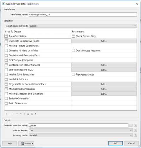
In order to check the validity of IFC data before storing in the database, GeometryValidator transformer in FME is used. shows the considered validation checks. After using this transformer and detecting the issues, the data cleaning process should be done. Therefore, the detected invalid building objects are fixed in the BIM model, and the BIM model is exported to IFC. Then, the validation process is repeated till all issues are resolved, and a clean IFC data is prepared for storing in the database.
Figure 7. Checking the validity of IFC elements using GeometryValidator transformer.
5.4. Mapping process, storing IFC data in a 3D spatial database
In order to store IFC data in the PostGIS database, IFC data types need to be mapped to database data types. shows the mapping of data types in FME to PostGIS data types. Noteworthy to mention that some of the IFC data types are assigned by FME, and they are different from IFC data types. For instance, GlobalID has the String data type in IFC, but FME considered Char data type for this attribute.
Table 3. Mapping IFC data types to PostGIS data types (attributes with * are defined in mapping and do not exist in IFC).
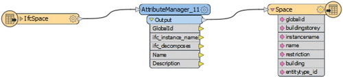
shows the mapping process for the IfcSpace entity. In this process, first, the IFC file is read by IFC Reader, and then the necessary attributes are grouped in Attribute Manager. Finally, these attributes are written in the database by PostGIS writer. In PostGIS writer, the attributes can be renamed, and new attributes can be added.
Figure 8. The mapping process for the IfcSpace entity.
In order to improve query performance in the database, the capability of partitioning the tables based on the buildings in which the entities of the table are located should be considered. However, there is no direct relation between a building and its associated building elements and the relation between building, and building elements is determined based on relations between building element, building storey, and building using the Instance Name attribute. Instance Name attribute is a label that is assigned to each instance of a collection in order to be able to identify the instance (BuildingSMART Citation2020b). However, Instance Name attribute is only unique in each IFC file (Shi et al. Citation2018). Consequently, if another building (new IFC file) is added to the database, Instance Name will not be unique anymore. Therefore, in order to be able to partition each table, the Building attribute which identifies the GlobalID of the building in which the entity is located is defined for all entities. Then, this attribute is used to partition each table based on the buildings in which the entities of the table are located.
For some elements such as IfcColumn, the Ifc_is_contained_in relationship, which refers to the building storey in which the column is located, only refers to the building storey that the base of the column is located. However, a column may be designed in a way that passes several building stories. Therefore, for the IfcColumn entity, the BuildingStorey attribute may not be a useful attribute since a column can be located in several stories. Therefore, storing the Building attribute is adequate for describing the location of a column.
In case of ‘EntityType_ID’, this attribute is defined as a new attribute in PostGIS writer. For instance, based on , ‘EntityType_ID’ for LegalSpace is 4, so 4 value is inserted in PostGIS writer. For other building elements, the same process is done. After importing one IFC file to the database, for importing other IFC files (a new building), only the IFC Reader part will be changed, and most of the parts remain unaffected. Based on , three attributes are inserted manually. EntityType_ID remains unaffected since this attribute defines an ID for each table in the database and for a new IFC data, the IDs will be the same. However, since Building and Site attributes are different for each IFC data, they should be updated if a new IFC data (building) is added to the database.
As mentioned in subsection 4.1, in case of IfcOccupant (owner of each legal space), IfcOccupant's Name does not show the stored value for Occupant attribute in Revit, and this value is defined as ObjectType attribute of IfcOccupant element. Generally, IfcOccupant is related to the IfcPerson entity by TheActor attribute, which refers to IfcPerson's InstanceName. Therefore, there are two options for the mapping process. First, changing the ObjectType alias to Name or defining a table for IfcPerson. Due to this fact that more tables in the database increase the complexity of schema, the first strategy (changing the alias) is a more efficient strategy. Therefore, the Name attribute for IfcOccupant table in the database is the ObjectType attribute in FME.
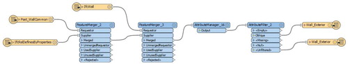
Furthermore, as noted before, due to the complexity of oblique structures, they are defined in the Revit software using a separate family type (Complex). After exporting to IFC, the Complex family type is defined as Reference attribute in the IFC common property set of building elements. In addition, the IFC common property set is connected to building elements (oblique walls and roofs) using IfcRelDefinesByProperties relation in IFC. Therefore, for instance, in case of walls, the workflow in is used. First, using the Instance Name attribute of wall common property set and Relating Property Definition attribute of IfcRelDefinesByProperties relation, these two features are merged. Then using the Instance Name attribute of the wall and Related Object attribute of the outcome of the previous merge, the Reference attribute is attached to each wall. In the next step, the Attribute Manager transformer is used to keep only the necessary attributes for storing in the database. Using Attribute Filter transformer, first, the walls with Complex value for Reference attribute are filtered, and in the first writer, the True value (Boolean) is stored for the Complex attribute in the database for these walls. Then, unfiltered walls (non-oblique walls) are stored in the database using the second writer, and False value (Boolean) is stored for the Complex attribute of these walls in the database. The same workflow is used for roofs. Therefore, non-oblique structures have False value for Complex attribute and oblique structures have True value for Complex attribute in the database.
Figure 9. The mapping process for IfcWall entity.
5.5. PostGIS data validation, data cleaning
After storing the data in the database, the validity of data in the database also needs to be checked. Since in the mapping process, first, the value of attributes is checked using AttributeManager transformer, and then in the PostGIS writer, the data types and ranges are controlled, semantic errors rarely happen. However, the validity of geometries is not checked during the mapping process.
As mentioned before, the object type of building elements in IFC is solid. However, after storing the data in the PostGIS database, solid geometry is converted to polyhedral surface geometry. When it comes to 3D data and polyhedral surface geometry, there are few functions that support a 3D polyhedral surface geometry in PostGIS. The only functions that can be used for checking the validity of the 3D polyhedral surface are ST_IsClosed and ST_IsPlanar. ST_IsClosed checks if the surface is areal (open) or volumetric (closed), and ST_IsPlanar checks the planarity of faces (PostGIS Citation2020). After using these functions and detecting invalid objects, the data cleaning process should be done. To do so, the design of detected invalid objects are checked in the BIM model (using Revit software). In order to clean the data, the building objects can be redrawn, and then the BIM model is exported to IFC. By repeating the process of checking the validity of IFC data, storing data in the database, and checking the validity of data in the database, all the objects are validated and prepared for performing spatial analysis.
5.6. Using the developed database for spatial analysis
For performing spatial analysis using the database, different methods can be used. For instance, for performing spatial analysis such as boundary identification analysis or accessibility analysis, topological and metric operators of the database can address all the requirements and there is no need to use another GIS software for performing these analyses. However, for performing some of the analyses such as flood risk analysis or solar access analysis in which the solar radiation model or flood model are needed, based on the required LoD in each analysis, only the objects with the same LoD are retrieved from the database and used for performing the analysis.
5.7. Visualisation
In case of performing spatial analysis using database operators solely (accessibility analysis, boundary identification analysis, etc.), FME Data Inspector software is used for visualising the results. Due to limitations of FME Data Inspector for visualising elements and lack of the capability of defining colours for elements by the user in this software, two transformers including Appearance Styler and Appearance Setter are used to define different colours for elements which have geometries in order to be able to showcase the results in a more tangible way. For spatial analyses that need GIS software, the software can address visualisation purposes.
6. Creating an IFC-based spatial database for 3D urban land administration
To prove the viability of the proposed methodology, architectural models of two multi-storey buildings located in Alphington, and South Yarra, Victoria, Australia, are used as datasets. Since the used real dataset did not have any oblique walls and roofs, a test dataset with oblique wall and roof also has been created (). Therefore, in the first step, legal data is added to the BIM model in Revit software. Then this model is georeferenced in ArcGIS Pro. The coordinate system is used in Australia is Geocentric Datum of Australia (GDA94), and Melbourne is located in Zone 55 (EPSG:28355). In the next step, the georeferenced data (including physical and legal data) is exported to IFC. Exporting a project with one building as dataset 2 is not challenging; however, exporting a project with two buildings is quite challenging since IFC exporter only considers one building in each project. Therefore, both buildings in dataset 1 will have the same GlobalId, which is not appealing for filtering objects of only one building in spatial analysis. To overcome this problem, dataset 1 should be divided into two separate projects, and each project should have just one building. Moreover, since the site element is common for both buildings, it should be only kept in one project to avoid redundancy. Subsequently, after exporting projects to IFC, two IFC files will be extracted. and show the exported IFC files from the BIM models of real datasets in the Solibri AnyWhere software which is a model viewer for IFC data. The size of the first dataset (building 1) is 17.648 MB and the size of the second dataset (building 2) is 10.894 MB. shows the number of elements for each IFC Type in all datasets.
Figure 10. The test dataset with oblique wall and roof in Revit.
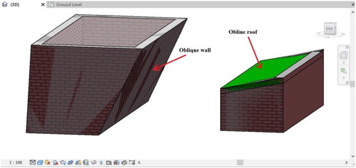
Figure 11. The IFC model of the first dataset in Solibri AnyWhere (light green solids show the legal spaces), (a) building 1, (b) building 2.
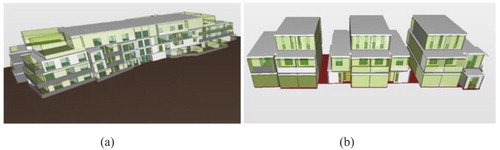
Figure 12. The IFC model of the second dataset in Solibri AnyWhere (light green solids show legal spaces).
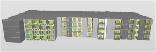
Table 4. Number of elements for each IFC type in datasets.
6.1. IFC data validation and cleaning
In order to prepare valid IFC data for storing in the database, IFC data validation and cleaning have been done. After using the GeometryValidator transformer for checking the validity of walls, all walls with doors and windows have been considered as invalid objects. The reason is based on the OGC SFS (Simple Features Specification for SQL) standard, the polygon in is invalid, which is the case for walls with doors and windows.
Figure 13. An invalid polygon based on OGC SFS standard (Open GIS Consortium Citation1999).
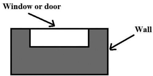
To overcome this problem, for checking the validity of walls, windows, and doors have been deleted. After deleting doors and windows for walls, one issue has been detected. This issue was related to the OGC simple compliant check, and the detected wall had a self-intersection. By redrawing the wall and repeating the process (exporting to IFC, checking the validity using GeometryVlidator transformer), the problem was solved.
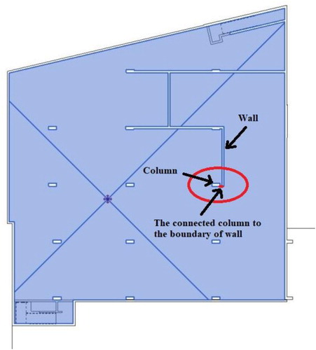
Other issues were related to IfcSpaces. In one of the common properties (), the designer has drawn a column close to a wall, and as a result, the boundary of column and wall are attached together which leads to an invalid object. In order to solve this problem and remove the connected red line between the column and the boundary of the wall, the column should be located in the right place with a slight distance from the wall.
Figure 14. Designing errors (a column attached to the boundary of a wall).
Since windows have complicated geometries, their correctness cannot be checked using the GemetryValidator transformer. On the other hand, windows are prepared building elements, and they are not drawn by architects and architects just put them in the right place. Therefore, it can be assumed that they are valid objects since they are less affected by designing errors. To sum up, the issues that have been detected in IFC data validation highly depend on the designing procedure and human errors.
6.2. Storing the valid IFC data in the PostGIS database
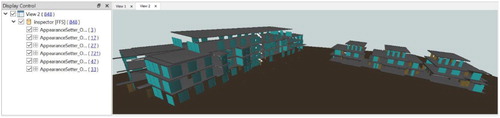
After preparing valid IFC data, in order to store the data in the database, the prepared IFC data is read in FME software, and after using different transformers, the data is written in the database. (a) shows the stored tables and elements in the PostGIS database (a legal space in building 2 has been selected and the information related to this legal space is provided on the right side). (b) also shows the stored elements for the test dataset with oblique walls and roof. In order to provide better visualisation, different colours are defined for different objects. shows the stored elements (zooming in dataset 1 data) after defining a specific colour for each element using Appearance Styler and Appearance Setter transformers (except for IfcSpace and IfcWall and IfcWallStandardCase).
Figure 15. The stored tables and elements in the PostGIS database, (a) a highlighted legal space in the dataset 2, (b) a highlighted legal space in the test dataset.
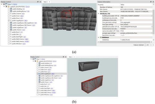
Figure 16. The stored elements in the PostGIS database after defining colours for elements (teal (IfcWindow), light brown (IfcDoor), dark brown (IfcSite), grey (IfcCovering, IfcSlab, IfcColumn)), white (IfcStairFlight).
FME software uses the Extract, Transform, Load (ETL) process to convert data from one data format to another format. Therefore, in order to store IFC data in the PostGIS database, first, the IFC reader converts IFC data into FME format, which is appropriate for the transformation process. In the next step, a series of rules or functions are applied in order to prepare data for loading into the database. Due to this fact that there is considerable complexity in geometry conversion, these conversions led to some issues in our work.
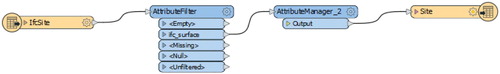
The first issue is related to the IfcWindow element. After reading IFC data, some of the windows had 2D geometries instead of 3D geometries. This problem was related to a specific type of window, and by changing the type of this window in Revit and repeating the IFC export process, this problem was solved. The second issue is related to the IfcSite element. IFCSite element originally was only one geometry in the IFC file; however, after conversion to FME geometry, this geometry converted to two geometries, including a surface and a line which represent the boundary of the surface. In order to solve this problem, the AttributeFilter transformer was used to keep only surface geometry and remove line geometry ().
Figure 17. The mapping process for the IfcSite entity.
The third issue is related to the IfcWallStandardCase element. The number of IfcWallStandardCase elements was duplicated since each wall was considered as two geometries, including a solid and a line that represents the centerline of the wall. Therefore, AttributeFilter transform was used for the IfcWallStandardCase element as well in order to remove line geometries and keep only solid geometries.
The fourth issue is related to the material of elements. After reading the IFC file, information related to the material of elements are not stored as traits of geometry, and they are only stored as textual attributes. Therefore, they cannot be used for visualisation. However, textual information is adequate for energy analysis. Therefore, by storing this information in the database, they can be used for energy analysis.
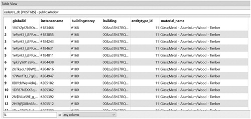
As shown in , the IfcWindow element has three layers for the material. In order to reduce the number of columns in the database and have a less complicated database, the AttributeConcatenator transformer was used. shows the whole process for storing the IfcWindow element in the database, and shows the resultant table in the database.
Figure 18. IfcWindow table in FME.
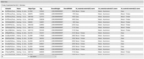
Figure 19. The mapping process for IfcWindow entity.
Figure 20. Window table in PostGIS database.
In addition to the material name, for the IfcWall and IfcWallStandardCase elements, material thickness is also important since it is one of the required information for energy analysis. Therefore, for the IfcWall and IfcWallStandardCase elements, two AttributeConcatenator transformers were used. One for creating the Material_name column and another one for creating the Material_thickness column.
6.3. PostGIS data validation and cleaning
As mentioned in the methodology, st_isclosed and st_isplanar functions are used for checking the validity of objects in the database. Therefore, the validity of walls is checked using these functions. However, st_isplanar only works for checking the planarity of a surface, not the planarity of faces of a solid. Therefore, first, faces of solid should be extracted, and then the planarity of faces of solid are checked using this function.
Apart from problems of walls with windows and doors in the IFC validation process, the PostGIS database also does not recognise solids with polygons similar to as valid objects (SFCGAL Citation2016). Therefore, the volume also cannot be computed for these solids. To overcome this problem, two tables have been created in the database, Wall_Exterior_without_holes table in which windows and doors have been removed from exterior walls and walls have no holes and Wall_Interior_without_holes in which doors have been removed from interior walls. Therefore, for instance, the following queries are used for validation of the Wall_Interior_without_holes table:
Select globalid from public. "Wall_Interior_without_holes" where st_isclosed (geom)=false;
With table_1 as (select (st_isplanar((ST_dump(geom)).geom)) as p, globalid from public. "Wall_Interior_without_holes" where st_isclosed(geom))
Select distinct globalid as g1 from table_1 where p=false;
After checking the validity of walls for both Wall_Exterior_without_holes and Wall_Interior_without_holes tables, three walls in two datasets (buildings) were not closed and their GlobalIds have been retrieved. However, there was not any clear solution for making invalid walls valid in this process. The only solution was redrawing walls and repeating the process. Although this process worked in the used datasets, still data validation is challenging and needs better solutions. Another problem was related to oblique walls and roofs. Since oblique structures have complicated geometry, they do not have planar surfaces. Therefore, the second validation check is failed for oblique walls and roofs. However, they can still be used for performing spatial analysis using topological and metric operators and bounding box function. In addition, although volume cannot be computed for the Wall_Interior and Wall_Exterior tables, still these tables can be used for performing spatial analysis using topological and metric operators and bounding box function.
For checking the validity of other objects such as IfcSpace, the mentioned queries were also used. Even for the test model with oblique walls, the legal space was a valid object. The validity of other objects such as columns, doors, and slabs also have been checked, but no problem has been detected.
7. Examples of required spatial queries in 3D urban land administration
In order to showcase the capabilities of the proposed database for 3D urban land administration, two use cases are considered. The first use case is related to solving boundary disputes in communal livings, and the second use case is related to retrieving boundary walls for each legal space. To find the final answer to each use case, several spatial queries need to be performed. The details of each use case and the required spatial queries are explained in the following subsections.
7.1. Query legal spaces related to a specific building element
2D Strata and subdivision plans are not always effortlessly understandable, and for solving disputes in communal living, it is often needed to consult a surveyor to find the legal boundaries and liabilities (Leshinsky and Libbis Citation2008).
As mentioned before, there are four different types of legal boundaries in the cadastral system of Victoria, including Interior, Exterior, Median, and Other boundaries. In communal living, different disputes may happen regarding the location of these boundaries. In order to solve these disputes, determining the liabilities is necessary. For instance, in a multi-storey building, if the boundary between two private properties is defined as an Interior boundary, the space inside of the wall is common property. Subsequently, if a pipe which is located within a wall leaks and causes damages, the Owners Corporation is the liable organisation for fixing the pipe. However, if the boundary between two private properties is defined as a Median boundary, property owners are responsible for fixing the pipe. Therefore, by retrieving the legal spaces related to the wall in which the pipe is located, lot owners and Owners corporation can find out their liabilities, and they can manage their boundary issues accordingly, and without seeking advice from an expert in the field (Barzegar et al. Citation2019).
In order to find the legal spaces related to the wall in which the pipe is located, several steps should be taken:
Selecting the wall from Wall_Interior table using its GlobalId
Selecting the legal spaces which are located on the same building and building storey as the wall
Using ST_3DIntersect function to find the legal spaces related to this wall
The following queries show the implementation of each step in the proposed database. Moreover, shows the final result of the provided spatial queries.
Figure 21. Legal spaces related to the selected wall.
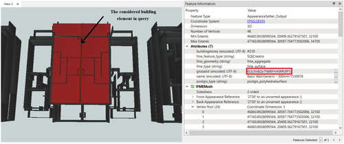
With table_1 as (select * from public."Wall_Interior" where globalid ='0Uz3ln$Qv7N8BPm KWRdfFS'),
Table_2 as (select a.geom as geom1, a.globalid from public."LegalSpace" a, table_1 b where a.buildingstorey = b.buildingstorey and a.building = b.building)
Select distinct b.geom1, b.globalid from table_1 a, table_2 b where ST_3DIntersects ((a.geom),(b.geom1));
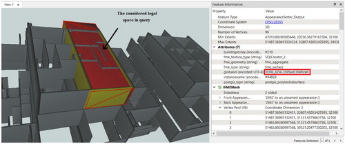
7.2. Query boundary walls for a specific legal space
Another application of spatial queries in 3D urban land administration is finding the walls defining 3D legal boundaries of a property. As mentioned before, there is no way to use virtual IfcRelSpaceBoundary relations for retrieving boundary walls associated with Exterior, Median, and Other boundaries from an IFC file. By using a 3D spatial database, this problem can be solved. In order to retrieve boundary walls, the below steps should be followed:
The faces of legal space are extracted using the St_dump function and stored in the Face table. This table has three columns, including face_number, geom, and space_globalid.
Due to this fact that horizontal faces of legal space (related to ceiling and floor) have also intersection with internal walls, if horizontal faces are considered in the analysis, the result of the intersection between walls and legal space will be both internal (located inside of legal space) and boundary walls (). Therefore, for detecting boundary walls, only vertical faces of legal space should be considered. To do so, st_area function is used to remove horizontal faces and keep just vertical faces (related to walls).
The walls which are located on the same building and building storey as the considered legal space are selected (from Wall_Exterior and Wall_Interior tables).
St_3Dintersects function is used to find the walls that have an intersection with vertical faces of legal space and are representatives of boundary walls.
Figure 22. A horizontal face of legal space has an intersection with both internal and boundary walls.
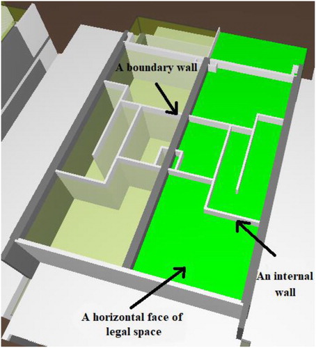
Figure 23. boundary walls for the considered legal space (property).
Create table Face (geom geometry, space_globalid varchar);
Insert into public. "Face" (geom)
Select (st_dump (geom)).geom as geom from public."LegalSpace" where globalid = '3DIM_BZAL3S95wtC0WRsWI';
Alter table public. "Face" add face_number serial;
Update public."Face" set space_globalid = '3DIM_BZAL3S95wtC0WRsWI';
With table_1 as (select * from public."Face" where st_area (geom)= 0),
Table_1_1 as (select building, buildingstorey from public."LegalSpace" where globalid = '3DIM_BZAL3S95wtC0WRsWI'),
Table_2_1 as (select * from public."Wall_Interior" a, table_1_1 b where a.building=b.building and a.buildingstorey = b.buildingstorey),
Table_2_2 as (select * from public."Wall_Exterior" a, table_1_1 b where a.building=b.building and a.buildingstorey = b.buildingstorey),
Table_2 as (select globalid, geom from table_2_1 union all select globalid, geom from table_2_2)
Select distinct b.name, b.geom, b.globalid from table_1 a, table_2 b where ST_3DIntersects ((a.geom),(b.geom));
8. Conclusion and future work
The limitations of IFC files in retrieving information have led to the development of IFC-based databases that support both spatial and attribute queries. However, in order to provide better functionality for the user, each database should be designed based on the spatial analysis requirements of a specific domain. Designing an IFC database based on the requirements of a specific domain would lead to reducing the number of tables and entities in the database and increasing its functionality. Moreover, it can be guaranteed that the designed database can answer all the analysis requirements of this domain. Therefore, in this study, an IFC-based database was developed based on the requirements of 3D urban land administration, and the viability of the database was tested using two real datasets and one test dataset with oblique walls and roof. This database can support both attribute and spatial queries and stores both physical and legal data, which are mandatory for doing spatial analysis in 3D urban land administration. In addition, a new method for modelling legal spaces with oblique walls and roof has been provided.
This work showed that creating a 3D spatial database for 3D urban land administration is highly affected by the designing stage, and an exact designing instruction is needed. For instance, in each project, only one building should be designed since in case of having two buildings in one project, both buildings will have the same GlobalID and non-differentiable. This case is more problematic if the BIM model is not accessible, and only the IFC file exists. In this situation, a new GlobalID should be generated for one of the buildings, and the whole hierarchy of the IFC model should be changed, which is an extremely difficult process.
Although in Victoria, Australia, architects mostly use Revit for designing BIM models, it should be noted that architects may use other BIM software such as SketchUp Pro. In addition, the first step of the provided methodology (adding legal data) has been developed based on the available tools in the Revit software, therefore, in future research, the required procedure for adding legal data in other BIM software should also be investigated.
Another important point that needs to be considered is validation and data cleaning stages need clear procedures. Although 3D validation rules have been identified in previous studies for legal spaces, a validation rule set for physical objects such as walls is also required. Therefore, future steps will be providing a general guideline for adding legal data in BIM models, developing 3D validation rule sets for physical objects, providing new strategies for data cleaning, and performing other 3D spatial analysis using the developed database. For instance, for assigning the type of boundary to each face of a building element (boundary identification analysis), several steps should be added to the provided spatial queries in section 5.2.2 which will be addressed in future work.
Disclosure statement
No potential conflict of interest was reported by the author(s).
Additional information
Funding
References
- “Oracle Spatial.” https://www.oracle.com/technetwork/database/options/spatialandgraph/overview/index.html.
- Oracle. “Three-Dimensional Spatial Objects.” https://docs.oracle.com/database/121/SPATL/three-dimensional-spatial-objects.htm#SPATL468.
- “PostGIS.” https://postgis.net/.
- Atazadeh, Behnam. 2017. “Building Information Modelling for Urban Land Administration.” PhD diss., The University of Melbourne. https://minerva-access.unimelb.edu.au/bitstream/handle/11343/150614/BehnamAtazadeh_PhD_Thesis.pdf?sequence=1&isAllowed=y.
- Atazadeh, Behnam, Mohsen Kalantari, Abbas Rajabifard, and Serene Ho. 2017a. “Modelling Building Ownership Boundaries Within BIM Environment: A Case Study in Victoria, Australia.” Computers, Environment and Urban Systems 61: 24–38. doi:10.1016/j.compenvurbsys.2016.09.001.
- Atazadeh, Behnam, Mohsen Kalantari, Abbas Rajabifard, Serene Ho, and Tom Champion. 2017b. “Extending a BIM-Based Data Model to Support 3D Digital Management of Complex Ownership Spaces.” International Journal of Geographical Information Science 31: 499–522. doi:10.1080/13658816.2016.1207775.
- Atazadeh, Behnam, Mohsen Kalantari, Abbas Rajabifard, Serene Ho, and Tuan Ngo. 2017c. “Building Information Modelling for High-Rise Land Administration.” Transactions in GIS 21. doi:10.1111/tgis.12199.
- Atazadeh, Behnam, Abbas Rajabifard, Yibo Zhang, and Maryam Barzegar. 2019. “Querying 3D Cadastral Information from BIM Models.” ISPRS International Journal of Geo-Information 8: 329.
- Australian Government. 2020. Subdivision Act 1988. https://content.legislation.vic.gov.au/sites/default/files/2020-04/88-53aa077 authorised.pdf.
- Autodesk. 2018. “Revit IFC Manual.” https://damassets.autodesk.net/content/dam/autodesk/draftr/2528/180213_IFC_Handbuch.pdf.
- Autodesk. 2020. “Create an In-Place Mass.” Reterived from: https://knowledge.autodesk.com/support/revit-products/learn-explore/caas/CloudHelp/cloudhelp/2018/ENU/Revit-Model/files/GUID-A180B32D-E7B8-474F-AB31-B15EDB874F6E-htm.html.
- Barzegar, Maryam, Abbas Rajabifard, Mohsen Kalantari, and Behnam Atazadeh. 2019. “3D BIM-Enabled Spatial Query for Retrieving Property Boundaries: A Case Study in Victoria, Australia.” International Journal of Geographical Information Science 34: 1–21.
- BuildingSMART. 2020a. “IFC Standard.” Accessed September 21, 2020. https://technical.buildingsmart.org/standards/ifc.
- BuildingSMART. 2020b. “Industry Foundation Classes - IFC2x Edition 3.” https://standards.buildingsmart.org/IFC/RELEASE/IFC2x3/FINAL/HTML/.
- Cagdas, Volkan, A. Kara, P. Van Oosterom, Christiaan Lemmen, Ü Ikda, R. Kathmann, and Erik Stubkjær. 2016. “An Initial Design of ISO 19152: 2012 LADM Based Valuation and Taxation Data Model.” Isprs Journal of Photogrammetry and Remote Sensing 4: 145–154.
- City of Melbourne. 2009. “Noise & Vibration Management Guidelines.” https://www.melbourne.vic.gov.au/building-and-development/planning-and-building-services/construction-development/legislation-guidelines/Pages/noise-and-vibration-guidelines.aspx.
- CUBRID. 2020. https://www.cubrid.org/cubrid.
- Daum, Simon, and André Borrmann. 2014. “Processing of Topological BIM Queries Using Boundary Representation Based Methods.” Advanced Engineering Informatics 28: 272–286.
- Department of Environment Land Water and Planning. 2020. “Planning Schemes.” http://planning-schemes.delwp.vic.gov.au.
- Enemark, Stig. 2005. “Understanding the Land Management Paradigm.” In Proceedings of FIG Commission 7 Symposium on Innovative Technologies for Land Administration, Madison, Wisconsin, USA.
- Enemark, Stig. 2009. “Managing Rights, Restrictions and Responsibilities in Land.” In GSDI-11 World Conference, Rotterdam, The Netherlands. http://vbn.aau.dk/ws/files/18418349/Enemark.pdf.
- Gröger, Gerhard, and Lutz Plümer. 2012. “CityGML–Interoperable Semantic 3D City Models.” ISPRS Journal of Photogrammetry and Remote Sensing 71: 12–33.
- Hietanen, Jiri. 2002. “BLIS Review: IMSvr.” http://63.249.21.136/software/reviews/IMSvr_Review.pdf.
- Ho, Serene. 2014. “Towards 3D-Enabled Urban Land Administration: Invisible Constraints and Strategic Choices.” PhD diss., The University of Melbourne. https://minerva-access.unimelb.edu.au/bitstream/handle/11343/52088/THESIS_HO.pdf?sequence=1.
- Isikdag, Umit, Mike Horhammer, Sisi Zlatanova, R. Kathmann, and P. J. M. Van Oosterom. 2014. “Semantically Rich 3D Building and Cadastral Models for Valuation.” Coordinates.
- Isikdag, Umit, Mike Horhammer, Sisi Zlatanova, Ruud Kathmann, and P. J. M. Van Oosterom. 2015. “Utilizing 3D Building and 3D Cadastre Geometries for Better Valuation of Existing Real Estate.” Proceedings FIG Working Week 2015 ‘From the wisdom of the ages to the challenges of modern world’, Sofia, Bulgaria, 17–21 May 2015.
- ISPRS EuroSDR GeoBIM benchmark. 2019. “Task 2 – Options for Georeferencing IFC Data.” https://zenodo.org/api/files/3fa7fa5e-aab9-4cac-8be4-8a5bb7d5b4cc/Task2_DeliveredResults_human.pdf.
- Kara, Abdullah, Volkan Çağdaş, Christiaan Lemmen, Ümit Isikdaq, Peter van Oosterom, and Erik Stubkjær. 2018. “Supporting Fiscal Aspect of Land Administration through a LADM-Based Valuation Information Model.” In Proceedings of the 19th Annual World Bank Conference on Land and Poverty.
- Kuehne, Don. 2019. “How to Georeference Revit Data in ArcGIS Pro.” Esri. https://www.esri.com/arcgis-blog/products/product/3d-gis/how-to-georeference-revit-data-in-arcgis-pro/.
- Land Use Victoria. 2015. “Building Subdivision Guidelines-Use of Buildings to Define Boundaries, Melbourne, Australia.” https://www.propertyandlandtitles.vic.gov.au/land-titles/subdivision-and-consolidation.
- Land Use Victoria. 2018. “The Valuation Best Practice Specifications Guidelines.” https://www.propertyandlandtitles.vic.gov.au/__data/assets/word_doc/0024/114738/2019-Valuation-Best-Practice-Specifications-Guidelines.docx.
- Latiffi, Aryani Ahmad, Juliana Brahim, Suzila Mohd, and Mohamad Syazli Fathi. 2015. “Building Information Modeling (BIM): Exploring Level of Development (LOD) in Construction Projects.” Paper presented at the Applied Mechanics and Materials.
- Lee, Ghang, Jiyong Jeong, Jongsung Won, Chiyon Cho, Seok-joon You, Sungil Ham, and Hoonsig Kang. 2014. “Query Performance of the IFC Model Server Using an Object-Relational Database Approach and a Traditional Relational Database Approach.” Journal of Computing in Civil Engineering 28: 210–222.
- Leshinsky, Rebecca, and Simon Libbis. 2008. Owners Corporations in Victoria: A Manual for Owners, Occupiers and Managers. Victoria: Hybrid Publishers.
- Li, Hang, Hua Liu, Yong Liu, and Yuan Wang. 2016. “An Object-Relational IFC Storage Model Based on Oracle Database.” International Archives of the Photogrammetry, Remote Sensing & Spatial Information Sciences 41.
- Mazairac, Wiet, and Jakob Beetz. 2013. “BIMQL – An Open Query Language for Building Information Models.” Advanced Engineering Informatics 27: 444–456.
- Olfat, Hamed, Behnam Atazadeh, Davood Shojaei, and Abbas Rajabifard. 2019. “The Feasibility of a BIM-Driven Approach to Support Building Subdivision Workflows—Case Study of Victoria, Australia.” ISPRS International Journal of Geo-Information 8: 499.
- Open GIS Consortium. 1999. “OpenGIS Simple Features Specification for SQL.” https://portal.opengeospatial.org/files/?artifact_id=829.
- PostGIS. “PostGIS Special Functions Index.” https://postgis.net/docs/PostGIS_Special_Functions_Index.html#PostGIS_PS_GeometryFunctions.
- PostGIS. 2020. “PostGIS Polyhedral Surface Support Functions.” https://postgis.net/docs/PostGIS_Special_Functions_Index.html#PostGIS_PS_GeometryFunctions.
- Property council of Australia. 1997. Method of measurement for lettable area. https://www.propertycouncil.com.au/ItemDetail?iProductCode=0105044&Category=PUB&WebsiteKey=148a29fb-5ee5-48af-954b-a02c118dc5fd.
- Rajabifard, Abbas, Behnam Atazadeh, and Mohsen Kalantari. 2019. BIM and Urban Land Administration. Boca Raton, FL: CRC Press.
- SFCGAL. 2016. “SFCGAL::Solid Class Reference.” https://oslandia.github.io/SFCGAL/doxygen/class_s_f_c_g_a_l_1_1_solid.html.
- Shi, Xin, Yu-Shen Liu, Ge Gao, Ming Gu, and Haijiang Li. 2018. “IFCdiff: A Content-Based Automatic Comparison Approach for IFC Files.” Automation in Construction 86: 53–68.
- Shin, Jihye, Abbas Rajabifard, Mohsen Kalantari, and Behnam Atazadeh. 2020. “Applying BIM to Support Dispute Avoidance in Managing Multi-Owned Buildings.” Journal of Computational Design and Engineering 7 (6): 788–802.
- Shukla, Deepika, C. Chirag Shivnani, and Darshit Shah. 2016. “Comparing Oracle Spatial and Postgres PostGIS.” IJCSE 7: 95–100.
- SketchUp. 2021. “Classifying Objects.” https://help.sketchup.com/en/sketchup/classifying-objects.
- Solihin, Wawan, Charles Eastman, Yong-Cheol Lee, and Dong-Hoon Yang. 2017. “A Simplified Relational Database Schema for Transformation of BIM Data into a Query-Efficient and Spatially Enabled Database.” Automation in Construction 84: 367–383.
- Sucaya, IKG Ary, and Ketut Gede Ary. 2009. “Application and Validation the Land Administration Domain Model in Real Life Situation: A Case Study in Indonesia.” ITC.
- UK BIM Alliance. 2019. “Information Management According to BS EN ISO 19650 (Guidance Part 1: Concepts).” https://www.ukbimalliance.org/wp-content/uploads/2019/03/Information-Management-according-to-BS-EN-ISO-19650-Guidance-Part-1-Concepts-1.pdf.
- Valez, Angel. 2018. “Exporting Zones.” https://sourceforge.net/p/ifcexporter/wiki/Exporting%20Zones/.
- Victorian Consolidated Regulations. 2015. “Surveying (Cadastral Surveys) Regulations.” http://extwprlegs1.fao.org/docs/pdf/vic152366.pdf.
- Ying, Huaquan, S. H. Lee, and Qiuchen Lu. 2016. “Comparative Analysis of the Applicability of BIM Query Languages for Energy Analysis.” In CIB W78 2016 Conference.
- Yu, Changbin, Lin Li, Biao He, Zhigang Zhao, and Xiaoming Li. 2017. “LADM-based Modeling of the Unified Registration of Immovable Property in China.” Land Use Policy 64: 292–306.
- Zhang, Lu, and Nora M. El-Gohary. 2020. Automated IFC-based Building Information Modelling and Extraction for Supporting Value Analysis of Buildings.” International Journal of Construction Management 20 (4): 269–288.
- Zhang, Hui, Yan Li, Biao Liu, and Chao Liu. 2014. “The Application of GIS 3D Modeling and Analysis Technology in Real Estate Mass Appraisal-Taking Landscape and Sunlight Factors as the Example.” ISPRS - International Archives of the Photogrammetry, Remote Sensing and Spatial Information Sciences XL-4: 363–367.