
 ?Mathematical formulae have been encoded as MathML and are displayed in this HTML version using MathJax in order to improve their display. Uncheck the box to turn MathJax off. This feature requires Javascript. Click on a formula to zoom.
ABSTRACT
Virtual construction has become an important approach to the high-quality development of high-speed railways, but existing methods have problems such as low efficiency in generating virtual construction scenes and the inability to reuse construction knowledge. To support the rapid visual representation of multiple types of construction processes and construction methods, a template-based knowledge reuse method is proposed. The method includes using a component-based modeling mode to build body structure models of a high-speed railway project and generate a 3D scene; decomposing the construction process and building a construction process knowledge base; establishing joint linkage models of construction machinery and forming a construction method knowledge template; and fusing multiple types of information according to a time sequence to visualize the construction process. Based on the template-based knowledge reuse method, a prototype system was developed, and virtual construction experiments were carried out. The results show that this method achieves the reuse of construction knowledge at different levels including construction machinery level, construction method level, and work site level. Compared with animation software for virtual construction, this method improves the production efficiency by 87%. Moreover, this method can provide a multilevel knowledge reuse scheme for diversified virtual construction.
1. Introduction
The construction of a high-speed railway is a huge, complex, and refined dynamic system project that includes multiple stages and involves multiple disciplines. There are the complexity of influencing factors, the dynamic nature of the construction process, and the uncertainty of interaction among objects in multiple disciplines (Lu and Cai Citation2019a). Through virtual construction, a user can preview or simulate physical construction activities in a virtual environment in real time and can use the ‘trial before construction’ method to prediscover problems that may arise in actual construction. Virtual construction contributes to the high-quality development of railway construction (Jiang et al. Citation2021; Lu et al. Citation2019b; Shirowzhan, Tan, and Sepasgozar Citation2020). However, the construction process of a high-speed railway is complex, and different types of construction machinery are required to complete the project construction of a high-speed railway in different processes. Moreover, different construction methods require different construction machines, and different machines act differently during construction operations. For example, the lifting of a steel cage requires the help of a truck crane whose actions include horizontal rotation, vertical rotation, boom telescoping, and lifting. When erecting a beam, it is necessary to use a beam erection machine. The construction operations of the beam erection machine include hoisting, walking, traversing, and braking. This makes the virtual construction process complex, time-consuming, and labor-intensive. Therefore, it is significant to propose a multilevel knowledge reuse method according to the characteristics of multiple types of construction methods.
Virtual construction (VC) is a technology that creates digital models of buildings and work sites by using graphics engines. Virtual construction is often visualized in the form of 3D animation, such as skeleton joint animation, frame animation, and path animation (Li and Li Citation2022; Sidani et al. Citation2021). The emphasis of a construction process varies with the graphics engine used. Existing research focuses on the use of the following three types of graphics engines: animation software, 3D GIS applications, and game engines.
It is achievable to make a virtual construction animation in animation software simply by making surface models or BIM solid models (Dashti et al. Citation2021; Park et al. Citation2018; Wu et al. Citation2019) and editing their skeleton joint actions. Virtual construction based on animation software focuses on the production of excellent visual effects and video animation but has defects in blending with surrounding terrain and in dynamic editing during operation. Some researchers built a virtual construction environment based on a 3D GIS application and studied the interaction between a body structure model and the surrounding geographical environment (Chenaux et al. Citation2019; Ning et al. Citation2020; Li et al. Citation2021a). In the construction management process of a high-speed railway, it is often necessary to use the 3D GIS technology to integrate data from multiple disciplines (Rurua, Shishinashvili, and Chubinidze Citation2018; Zhang et al. Citation2016). Therefore, this method focuses on integrating the surrounding geographical environment of the construction site and can effectively use a prebuilt 3D scene to reduce the cost and production time of virtual construction, but the visual representation effect of this method is not quite realistic (Chen and Lin Citation2018). A game engine is a tool available for a game designer to code and plan out a video game quickly and easily instead of building one from the ground up. Whether a game engine is based on 2D or 3D, it serves as a tool to aid in asset creation and placement. Virtual construction based on a game engine focuses on realistically representing physical effects such as collision and gravity and can produce an immersive VR/AR experience (Boton Citation2018; Wang et al. Citation2018; Li et al. Citation2021b). However, this method is applicable to only site-level virtual construction and cannot perform terrain excavation dynamically, such as excavation of foundation pits during construction.
The above studies have all contributed to the virtual construction of a high-speed railway. However, due to the failure to extract and express construction knowledge in a structured manner, existing construction knowledge cannot be efficiently reused when facing diversified construction methods, leading to problems such as being error-prone, inefficient, time-consuming, and labor-intensive. The existing research on construction knowledge focuses on expression and storage of knowledge and lacks practical application in terms of knowledge reuse. For example, some studies used methods such as ontology or knowledge graphs to build geoscience knowledge systems (Jiang et al. Citation2019; Wang et al. Citation2019; Xue et al. Citation2019). Moreover, some studies used knowledge graphs to standardize the knowledge of safety, quality, and progress during railway construction (Liu et al. Citation2021; Zhu et al. Citation2022a). One of the most valuable and fundamental uses of knowledge graphs is to express relationships between data. Some studies used templates to describe 3D scene modeling knowledge, thereby achieving the reuse of scene modeling knowledge and the automatic generation of multitype scenes (Zhang et al. Citation2018, Citation2019). Both knowledge graphs and templates are used to store and express knowledge, but they adopt different data models. A knowledge graph uses a graph-structured data model or topology to integrate data, while a template uses a key–value data model. However, the proposed knowledge template is mainly used to describe the generation method of a static 3D scene. The parameters in the template are used to describe the static spatial relationships between railway infrastructure structures, and there is a lack of dynamically changing spatio-temporal relationships during construction. Therefore, it is significant to propose a method that takes into account the requirements of diversified construction methods in a virtual construction process and uses knowledge engineering to explicitly represent the spatio-temporal dynamic changes in high-speed railway construction factors (Terentyeva et al. Citation2020; He et al. Citation2019; Wang Citation2019, Citation2021).
Regarding the differences between multiple types of construction methods, the following two key problems need to be solved to achieve a unified virtual construction method: (1) The primary problem to be solved is how to carry out digital twin modeling of a construction process and digital twin modeling of a construction method to support the 3D visualization of construction machinery operations. Virtual construction involves the visual representation of a construction process and the visual representation of a specific construction method. Digital twin modeling of a construction process can visually show steps of the construction process at the macro level. In addition, digital twin modeling of a construction method can show the construction method at the micro level. (2) The other problem to be solved is how to carry out extraction and structured storage of virtual construction knowledge to support the reuse of virtual construction knowledge. Virtual construction is a process of visual representation of different construction processes and construction methods. The differences in construction processes and construction methods in different projects lead to low efficiency of virtual construction. The extraction and unified expression of construction knowledge contribute to knowledge reuse in diversified construction processes and methods, thereby effectively reducing repetitive editing of virtual construction and greatly improving the efficiency of virtual construction. Therefore, it is significant to solve the problem of how to extract and condense the common characteristics of different types of construction methods to form structured knowledge.
To solve the problem that diverse construction methods are difficult to represent uniformly, a template-based knowledge reuse method is proposed. This paper aims to form a unified structured knowledge template by decoupling professional knowledge from the virtual construction process to achieve knowledge reuse, save time, and reduce costs. The remainder of this paper is organized as follows.
Section 2 describes the method of this paper. In section 2, section 2.1 expounds the overall framework of this paper; section 2.2 presents the automatic generation of high-speed railway scenes based on model assembly; and section 2.3 discusses the virtual construction method from the following three aspects: joint linkage of construction machinery, construction method knowledge template, and visualization of virtual construction. Section 3 describes conduction of knowledge reuse experiments and analyzes the experiments at the construction machinery level, the construction method level, and the work site level. Section 4 presents concluding remarks and future work.
2. Methodology
2.1. Overall framework
A digital twin is a virtual model designed to accurately reflect a physical object. There are various types of digital twins depending on the level of product magnification. In this paper, there are three types of digital twins: railway infrastructure twins (section 2.2), construction process twins (section 2.3.1), and construction method twins (section 2.3.2 and section 2.3.3). shows the overall framework of this paper. The framework includes the following steps.
Figure 1. Overall framework.
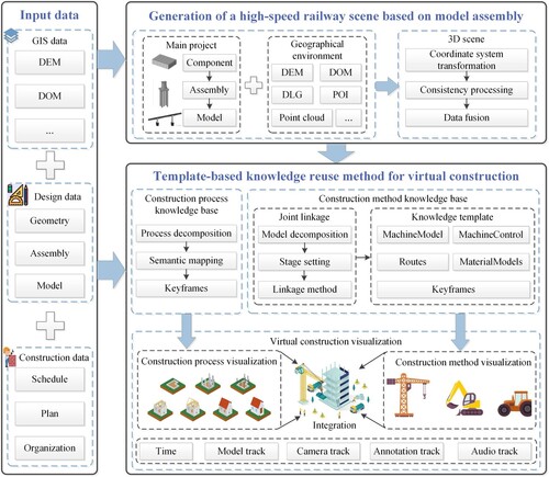
(1) Generation of a high-speed railway scene based on model assembly
An infrastructure model is built using a multigranularity model assembly method. The model is reassembled automatically in the geographic coordinate system through transformation between multiple coordinate systems. The infrastructure model is integrated with geographic data to provide a digital foundation for virtual construction.
(2) Template-based knowledge reuse
A construction process is decomposed into multiple operation steps. Each step is mapped to a keyframe. The parameters (including model growth parameters, coloring parameters, and movement parameters) of each keyframe are extracted to a process knowledge file. The collection of these process knowledge files constitutes a construction process knowledge base. A construction machine is decomposed into child models, a linkage relationship is established between each child model and its parent, and a construction method is stored in a unified construction method knowledge template in a parametric form. Knowledge files are derived from the template to form a construction method knowledge base. The construction process knowledge base is used for visualization of a construction process. The construction method knowledge base is used for visualization of a construction method. According to the sequence of construction steps, the virtual construction can be completed by integrating the visualization of the construction process and the visualization of the construction method.
2.2. Generation of a high-speed railway scene based on model assembly
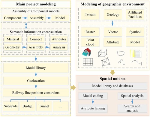
2.2.1. Modeling of the main project and its surrounding environment
The main project of a high-speed railway is built using a multigranularity model assembly method. The basic unit of the modeling is a component. There are two ways to make a component model: automatically making the component by analyzing the design parameters, and extracting the component model from a model library. The geometric parameters, functional parameters, and spatial topology parameters are encapsulated in the modeling process, and component models are assembled through the step-by-step transformation of the coordinate system. Based on information such as geometric entities, codes, model relationships, and attributes, a 3D model library with complete attribute information is formed to achieve flexible encapsulation of parameters and efficient reuse of models.
In addition, modeling of terrain, geology, ancillary facilities, and the surrounding environment is performed using raster data, vector data, and point cloud data. According to the result of modeling of the main project and the spatial environment, a spatial unit set is created. Then, a unique code is assigned to each spatial unit to facilitate the linking of attribute data. shows the modeling process of the spatial unit set.
Figure 2. Modeling of the main project and its surrounding environment.
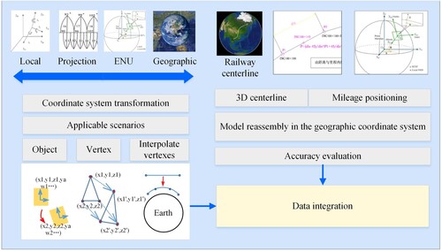
2.2.2. Automatic generation of a high-speed railway scene
First, the models of the main project are reassembled in the geographic coordinate system, as shown in . To solve the problem of inaccuracy in the process of transformation between multiple coordinate systems, transformation methods at different levels are used: the object level, the vertex level, and the vertex interpolation level. The transformation method at the object level converts the coordinates of a 3D model as a point, the transformation method at the vertex level converts the coordinates of the vertexes of a 3D model one by one, and the transformation method at the interpolation level converts the coordinates of the lines of a 3D model by vertex interpolation. With these transformation methods at multiple levels, line position data of the high-speed railway in the local or projection coordinate system is transformed into a 3D centerline in the geographic coordinate system. In this manner, the mileage coordinates are converted into spatial coordinates so that the 3D models of the railway are reassembled in the geographic coordinate system.
Figure 3. Reassembly of models in the geographic coordinate system.
Then, consistency processing is performed on the multimodal spatial data, as shown in . High-speed railway engineering involves many disciplines, and both software and data formats used in modeling differ in different disciplines. Therefore, consistency processing is required so that geometric information in different projects can be in the same format. With regard to information description, consistency processing on structural composition is required. The real world is described by means of geometric entities, relationships, and attributes. Multimodal spatial data is described using a unified metadata standard. Spatial information is described using a unified spatial location code, which includes a Beidou grid location code and a track mileage value. Then, the Boolean processing is performed on model–model fusion and model–terrain fusion.
Figure 4. Consistency processing on the multimodal spatial data.
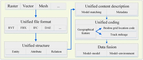
After consistency processing on the multimodal spatial data is completed, the multimodal spatial data is managed in layers. These layers constitute a high-speed railway scene.
2.3. Template-based knowledge reuse method for virtual construction
Virtual construction of a high-speed railway involves digital twin modeling of a construction process and digital twin modeling of a construction method (Ning et al. Citation2020).
A construction process refers to a series of construction operation steps in each stage of a project. For example, a formwork must be erected before concrete is poured. Construction process twins, the macro level of magnification, reveal how systems work together to create an entire production facility. Through digital twin modeling of a construction process, a user can preview the construction process and steps of building construction so that the user can have an overall and macroscopic understanding of the construction process and steps (Zou, Kiviniemi, and Jones Citation2017). Moreover, through digital twin modeling of a construction process, a user can control different states (including displayed, hidden, and colored) of a 3D model by using time information.
A construction method is a procedure and technique used during a construction process. For example, a box girder is erected by means of a bridge erecting machine. Construction method twins reveal how construction machinery builds railway infrastructures. With the help of a construction machine and construction materials, digital twin modeling of a construction method is a 4D visual representation of a specific method such as a method for lifting a steel cage or a method for erecting a beam (Moon and Seo Citation2017). After a construction method is visually represented, a user can have a better understanding of the construction method, and quality and safety accidents are less likely to occur. Digital twin modeling of a construction method includes linkage modeling between a child model of a machine and its parent and linkage modeling between the construction machine and construction materials.
2.3.1. Construction process knowledge base
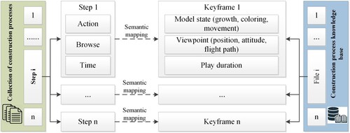
A construction process is decomposed into multiple construction steps, and each construction step is mapped to a keyframe. The keyframes are played dynamically according to a time sequence so that the construction process is visualized, as shown in . First, the construction process is decomposed into operation steps. Each operation step is a construction action and is assigned a duration. Time intervals are assigned between the operation steps. Then, the operation steps are mapped to video keyframes. The construction action is mapped to a video action such as growth, coloring, or movement of a model. The browsing mode of the scene is mapped to browsing parameters including viewpoint position, viewpoint attitude, and flight path. The duration of each construction step is mapped to the play duration of a keyframe. The collection of these keyframes constitutes a construction process knowledge base. By parsing and interpolating the keyframes in the 3D scene, a frame animation is created.
Figure 5. Construction process knowledge base.
2.3.2. Joint linkage of construction machinery
A construction method involves the use of construction machinery. Therefore, joint animation is required to represent the linkage between models. In this paper, a construction machine model is decomposed, a linkage relationship is established between each child model and its parent, joint activity parameters are extracted, and construction control parameters are extracted according to the dynamic visualization requirements of high-speed railway construction. A mathematical model for mapping from construction control parameters to joint motion parameters is established. The position of each child model relative to its parent is determined, and a linkage model is built between each child model and its parent. Through the step-by-step transformation of the multilevel coordinate system, the position and attitude parameters of each child model in the 3D scene are obtained so that individual child models can move in different planes at the same time.
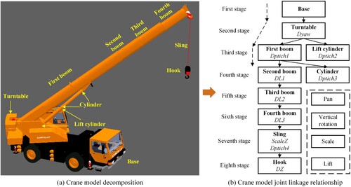
The joint linkage method of a construction machine is illustrated using a crane model as an example. First, the crane model is decomposed into child models, and the activity parameters of each child model and the stage of each child model are determined, as shown in . Then, according to user operating habits, four construction control parameters are determined: the rotation angle of the crane turntable relative to the bottom of the crane, that is, the azimuth angle A1 of the crane turntable; the lift angle of the crane boom, A2, which describes the angle by which the boom is lifted; the telescopic length L1 of the boom; and the lift length L2 of the hook. A model for mapping from the construction control parameters to the joint activity parameters is established, and joint linkage mathematical models are established, as shown in Formula (1).
(1)
(1) In the formula, Dyaw denotes the rotation angle of the crane turntable, and A1 denotes the azimuth angle of the crane turntable. Dpitch1 denotes the angle by which the boom is rotated vertically, and A2 denotes the lift angle of the boom. Dpitch2 denotes the angle between the bottom of the lifting cylinder and the horizontal line. Sa, Sb, and β are all fixed values, denoting the relevant fixed parameters of the construction machine model. Sc denotes the length from the lifting cylinder to the cylinder, which varies with the lifting of the boom. Dpitch3 denotes the angle between the top of the lifting cylinder and the horizontal line, which is the supplementary angle of Dpitch2. Dpitch4 denotes the angle by which the sling is rotated vertically. DLi denotes the telescopic length of the ith-stage boom, di denotes the distance between the ith-stage boom and the (i + 1)th-stage boom, and L1 denotes the telescopic length of the boom. Both ScaleZ and L2 denote the length of the sling. DZ denotes the elevation difference between the hook and the top of the sling.
Figure 6. Crane model decomposition and joint linkage relationship.
2.3.3. Construction method knowledge template
Although the types of construction machinery are different, high-speed railway projects are the same in terms of virtual construction. First, the construction machine model is decomposed into child models; then, a joint linkage relationship is established between each child model and its parent, and joint animation is used to represent the dynamic changes of construction; finally, the joint animation is converted into frame animation for play. Therefore, the parameters and algorithms of virtual construction can be encapsulated into a unified template file. According to the different operation modes of different construction machines, the parameters in the template can be modified to instantiate the template into multiple documents. The collection of these documents constitutes a construction method knowledge base. The relationship between a template and an instance document is similar to that between a class and an object. A template file is equivalent to a class, and parameters in the template are equivalent to properties in the class. An algorithm in the template is a function in the class, and the instance document is an instance object derived from the class. shows the structure of a construction method knowledge template file.
Figure 7. Construction method knowledge template.
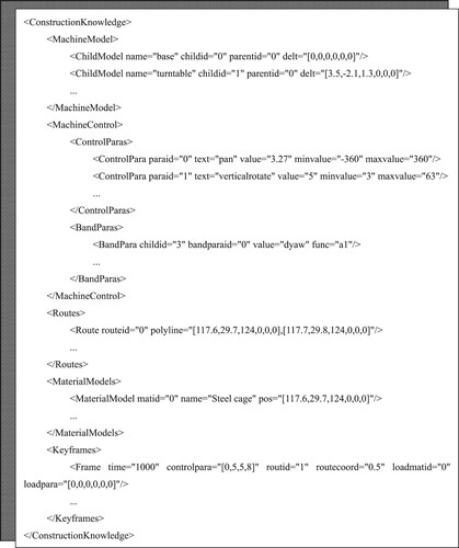
(1) Machinemodel
The decomposition result of the machine model, the structural relationship between each child model and its parent, and the relative positional relationship between each child model and its parent are recorded using the XML node MachineModel. Specifically, the structural relationship is recorded by the fields id and parented, and the relative positional relationship is recorded by the field delt. The relative positional relationship includes position offsets (dx, dy, dz) and angle differences (dyaw, dpitch, droll), as shown in Formula (2).
(2)
(2)
(2) Machinecontrol
The XML node ControlParas includes user-oriented construction control parameters and binding parameters between each child model and its parent. The construction control parameters are displayed on the user control panel, facilitating interactive control by a user.
The binding relationship between each child model and its parent is recorded by the field BandParas. The field childid is the ID of a child model. The field bandparaid is the ID of a parent model. The fields value and func record a formula representing the linkage between each child model and its parent. In , the formula representing the binding relationship is Formula (3).
(3)
(3)
In the formula, the field dyaw denotes a change in a yaw angle when a child model moves with its parent. The field a1, a horizontal rotation parameter, denotes the first parameter in ControlPara.
(3) Routes
The movement paths of the construction machine model in the 3D scene are recorded using the XML node Routes. A route is composed of multiple polylines, and each polyline is composed of 3D points. A 3D point contains the spatial position and the attitude information of the point, as shown in Formula (4).
(4)
(4)
In the formula, x, y, and z are 3D coordinate values in the geographic coordinate system, and yaw, pitch and roll are attitude parameters.
(4) Material models
Materials, such as a steel cage and a beam, handled by the construction machine are recorded using the XML node MaterialModels. In , the parameter pos denotes the spatial position and attitude where a material model is placed.
(5) Keyframes
A step of virtual construction can be mapped to a keyframe, and the collection of these keyframes is the animation representation of the virtual construction. See . The parameter time denotes the play duration of a keyframe. The parameter controlpara denotes the value of the four control parameters in a keyframe. The parameter routeid denotes the serial number of the route along which the construction machine model moves. The parameter routecoord denotes the sequence number of a coordinate point on the route. The parameter loadmatid denotes the ID of the material model loaded by the construction machine model. The parameter loadpara denotes the relative positional relationship between the material model and the last stage of child model.
2.3.4. Visualization of virtual construction
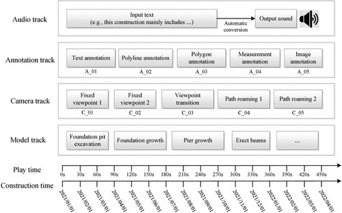
Both the construction process knowledge base and the construction method knowledge base store knowledge in the form of frame animation. The frame animation is parsed, and the state of each feature in the 3D scene is changed according to a time sequence so that virtual construction is visualized. First, a mapping is established between the actual construction duration and the play duration of the frame animation. The frame animation is divided into multiple tracks, including a camera track, a model track, an annotation track, and an audio track. The camera track records the position, attitude, viewport, and orientation of a camera in the 3D scene. The model track records model growth actions, model skeleton joint actions, and model colors. The annotation track records information such as POIs by using text and images. The audio track records sound transformed from text by using an intelligent sound library. Finally, information fusion is performed between the four tracks so that a virtual construction animation is generated, as shown in .
Figure 8. Visualization of virtual construction.
3. Template-based virtual construction knowledge reuse experiment and analysis
3.1. Case description
Railway construction can be divided into two categories: macroscopic construction processes and microscopic construction methods. A construction process is used to show the construction steps at the macro level, and a construction method is used to show the construction machinery and specific methods at the micro level. The method of this paper also applies to underground spatial objects such as underground stations, foundation pits, and tunnels. The method in this paper can provide 3D scenes for virtual construction. The focus of this paper is to introduce the knowledge reuse method of scene generation. Therefore, we will not describe in detail a living digital twin in which physical data is embedded into the virtual realm in order to feed it.
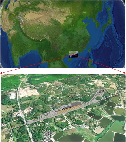
An experiment of virtual construction of a bridge of a high-speed railway was conducted. First, a bridge model was built using the model assembly method described in section 2.2.1. Then, the mileage coordinates of the bridge model were converted into geographic coordinates, and a high-speed railway scene was generated (see ). Then, the construction process of the bridge was decomposed, and a construction process knowledge base was generated. The mathematical models of the joint linkage of various construction machinery were established so that a construction method knowledge base was formed. The two knowledge bases were parsed so that the construction process was visualized. Finally, knowledge reuse experiments were carried out at three levels: the construction machinery level, the construction method level, and the work site level.
Figure 9. High-speed railway scene.
3.2. Experimental analysis
Virtual construction of a high-speed railway is often carried out using 3D modeling software and animation software. 3D modeling software (such as C4D, 3ds max, and Blender) has certain 3D modeling capabilities. Animation software such as Rhino3D, Lumion, and Twinmotion has capabilities of editing the construction process dynamically. If the virtual construction work is carried out in the modeling software, the final output is a noneditable video file. Once the construction process changes, it is necessary to recreate the animation, which is time-consuming and labor-intensive. If virtual construction is carried out in animation software, although the construction process can be dynamically controlled, the construction knowledge is tightly coupled with the modeling software, resulting in the inability to reuse construction knowledge. In addition, the above two methods are limited to the work site level, and it is difficult to load large-scale geographic scene data. As a result, the dynamic relationship between the work site and its surrounding real geographical environment cannot be visualized. summarizes a comparison between our method and the above two methods.
Table 1. Advantages of our method.
3.2.1. Knowledge reuse at the construction machinery level
The construction of high-speed railway projects needs to be completed with the help of various types of construction machinery, such as cranes, bridge erecting machines, and excavators. When visualizing the construction process, it is necessary to edit the motion and operation mode of each type of construction machinery separately. Once the scene data or the construction environment changes, the operation mode of the construction machine needs to be re-edited.
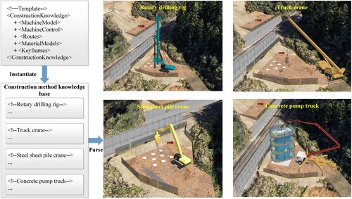
Since each type of construction machinery conforms to the law of joint linkage during operation, this law can be extracted as a parameterized template, which is suitable for different types of construction machinery and different operation methods. The parametric information such as relative positional relationships and linkage relationships was extracted to make a unified template structure, so that construction knowledge can be reused. shows the effect of construction knowledge reused by different construction machines. The upper left corner of shows the construction method knowledge template file, which contains parameter information such as MachineModel, MachineControl, Routes, MaterialModels, and Keyframes. According to the action characteristics of different construction machines, the construction knowledge template can be instantiated into different construction method knowledge files. The lower left corner of shows the knowledge files instantiated according to the construction method knowledge template, including the knowledge files of Rotary drilling rig, Truck crane, Steel sheet pile crane, and Concrete pump truck. These knowledge files form the construction method knowledge base. By parsing the construction method knowledge base, the corresponding construction machine model can be used in the 3D scene for virtual construction. The right side of shows the virtual construction process of these four construction machine models.
Figure 10. Knowledge reuse at the construction machinery level.
3.2.2. Knowledge reuse at the construction method level
During the construction of a high-speed railway project, subitem projects are similar in terms of shape and regular in terms of spatial distribution, so some construction methods, for example, the construction method for setting up multiple beams on the beam frame and the method of lifting multiple steel cages by cranes, are similar. Repetitive construction scene editing processes lead to a waste of manpower and resources.
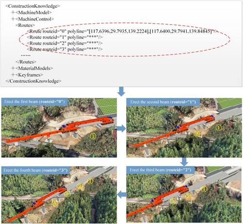
The construction knowledge template in this paper not only stores the specific parameters of the construction method, but also stores the movement route of the construction machinery. By modifying the motion path parameters, the construction method can be reused, thereby avoiding the problem of repeated editing of the same construction method. uses the beam erection operation as an example. Multiple motion paths were added in a construction method knowledge file. The coordinate position of each path can be modified to carry out beam erection operations in different spatial positions, thereby the construction method can be reused. The upper part of shows the editing methods for different routes in the construction method knowledge file. The lower part of shows the 3D effect of automatically erecting 1–4 beams by a beam erecting machine by parsing the construction method knowledge file.
Figure 11. Knowledge reuse at the construction method level.
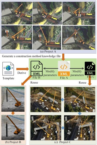
Knowledge of construction methods can be reused not only in the same project, but also in different projects. First, 3ds Max, SketchUp, or other modeling software is used to make construction machine models, and they are imported into the 3D railway scene. Then, the virtual construction software is used to edit the operation animation of the construction machine model. The operation animation results of virtual construction are finally stored in an xml file, which is the construction method knowledge file derived from the template. Finally, when encountering other virtual construction projects, the virtual construction software is used to open the local construction method knowledge file, and the operation parameters are edited to complete the virtual construction. shows the effect of construction method knowledge reuse into other projects. In , (a) shows the process of using the crane to install the tower crane in project A, (b) shows the process of using the crane to lift the steel cage in project B, and (c) shows the process of using the crane to lift the box girder in project C. After project A is completed, file A is generated. By modifying the parameters in file A, file B and file C can be generated. File A, File B, and File C are all derived from the construction method template. These three files have the same structure, the only difference is the parameters in the files. By importing file B and file C into the virtual construction software, project B and project C can be carried out to achieve knowledge reuse.
Figure 12. Knowledge reuse between different projects.
3.2.3. Knowledge reuse at the work site level
Each 3D model in the high-speed railway scene has the characteristics of fixed type and standard size; and the arrangement of these 3D models follows obvious linear laws. As a result, work sites of the same type have the same construction mode, and even the construction of a bridge in a high-speed railway project may be similar to the construction of a bridge in another high-speed railway project.
A method of top-down decomposition and bottom-up packaging was used for virtual construction. First, different types of construction machinery were used to meet the representation needs of diverse virtual constructions. Then, the construction process knowledge base and the construction method knowledge base were built. The dynamic model growth method was used to achieve the reuse of construction process knowledge, and the joint linkage method was used to achieve the reuse of construction method knowledge. Finally, the combination of construction processes and construction methods constitutes the virtual construction of the entire work site.
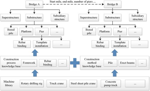
uses bridge construction as an example to illustrate knowledge reuse at the work site level. The bridge construction was decomposed into substructure construction, superstructure construction, and auxiliary engineering construction. Each substructure was decomposed into leaf structures such as bored piles, piers, caps, and top caps. The construction process of each bridge pier includes steel bar binding, formwork installation, concrete pouring, and other processes. Moreover, bridge pier construction needs to be completed with the help of different construction machinery. By modifying the parameters such as the starting mileage, the ending mileage, and the number of hole spans, the construction knowledge of bridge A can be reused by bridge B so that the virtual construction work can be quickly completed.
Figure 13. Knowledge reuse at the work site level.
3.2.4. Comparison of virtual construction efficiency
Virtual construction often requires visual representation with the help of animations. Conventional methods usually use modeling software such as C4D and 3ds max for virtual construction, leading to low efficiency because construction knowledge cannot be effectively reused. In contrast, in our method, the construction knowledge can be stored in the xml file in a parametric form so that the construction knowledge can be effectively reused and the efficiency of virtual construction can be improved. When a virtual construction animation is created, the same process and construction method can be reused. Moreover, when a different virtual construction animation is created, the previously built construction method knowledge library can be reused.
compares the efficiency of the method of this paper with the efficiency of virtual construction animation by use of animation software (for example, C4D). When a virtual construction animation is built using animation software, after the user is able to operate the software proficiently, the work efficiency is linearly related to the number of projects. When the method of this paper is used at the beginning, since there are some construction method knowledge files in the construction method base, it only takes 5 h to complete a virtual construction animation. With the increase in the number of virtual animations produced, a lot of construction method files are accumulated. At this time, when a user wants to make a new animation, he only needs to use the previously made construction method knowledge files, which greatly improves the production efficiency. When 10 virtual construction animations are created, this method can increase the production efficiency by 87% compared with C4D software. Therefore, as the number of virtual construction projects increases, the knowledge reuse method proposed in this paper increasingly improves the production efficiency of virtual construction.
Table 2. Comparison of virtual construction efficiency (Unit: h).
4. Conclusions
To address the difficulty in effectively reusing construction methods and construction knowledge, a template-based knowledge reuse method was proposed for high-speed railway virtual construction scenes. The model assembly method was used to achieve multigranularity assembly of scene objects. The construction process knowledge base, the joint linkage method of construction machinery, and the construction method knowledge base were then established to achieve virtual construction based on a geographic environment. The method of this paper can effectively improve the production efficiency of virtual construction scenes and achieve knowledge reuse at three levels:
A virtual construction method knowledge template was designed to achieve knowledge reuse at the construction machinery level. The common characteristics of multiple types of construction machinery were extracted, keyframes were used to semantically describe the characteristics of the construction process, and the linkage method was established. A unified structured parameter template was designed to store the construction knowledge. According to the operation characteristics of different construction machinery, the virtual construction method knowledge template was instantiated to achieve knowledge reuse at the construction machinery level so that the diversity of virtual construction scene representation was improved effectively.
The virtual construction process was described parametrically so that knowledge reuse at the construction method level was achieved. The construction process was decomposed, the method of model growth, coloring, and movement was designed, and the construction process knowledge base was created at the macro scale. The joint linkage method of the construction machine model was studied, and the construction method knowledge base was created at the microscopic scale. Parametric description and storage of the knowledge bases were carried out so that knowledge reuse of similar construction processes and construction methods was achieved, and the production efficiency of virtual construction scenes was improved effectively.
The method of top-down decomposition and bottom-up encapsulation was used to achieve knowledge reuse at the work site level. The virtual construction process was divided into many operation actions. Keyframe parameters were used to describe a construction action and different states (including displayed, hidden, and colored) of a 3D model. Based on the reusability of the machine library, the construction process knowledge base, and the construction method knowledge base, knowledge reuse at the work site level was achieved.
In future work, we will study precise mappings between physical entities of various facilities and their digital virtual bodies. By establishing a bidirectional mapping mechanism, we can perceive, diagnose, and predict a high-speed railway construction process to optimize the actual construction process.
Disclosure statement
No potential conflict of interest was reported by the author(s).
Additional information
Funding
References
- Boton, C. 2018. “Supporting Constructability Analysis Meetings with Immersive Virtual Reality-Based Collaborative BIM 4D Simulation.” Automation in Construction 96: 1–15. doi:10.1016/j.autcon.2018.08.020.
- Chen, M., and H. Lin. 2018. “Virtual Geographic Environments (VGEs): Originating from or Beyond Virtual Reality (VR)?.” International Journal of Digital Earth 11 (4): 329–333. doi:10.1080/17538947.2017.1419452.
- Chenaux, A., M. Murphy, S. Pavia, S. Fai, T. Molnar, J. Cahill, S. Lenihan, and A. Corns. 2019. “A Review of 3D GIS for use in Creating Virtual Historic Dublin.” The International Archives of Photogrammetry, Remote Sensing and Spatial Information Sciences 42: 249–254. doi:10.5194/isprs-archives-XLII-2-W9-249-2019.
- Dashti, M. S., M. RezaZadeh, M. Khanzadi, and H. Taghaddos. 2021. “Integrated BIM-Based Simulation for Automated Time-Space Conflict Management in Construction Projects.” Automation in Construction 132: 103957. doi:10.1016/j.autcon.2021.103957.
- He, H., L. Zhu, P. Li, and J. Zheng. 2019. “Study on the System Framework of Intelligent High-Speed Railway.” China Railway 3: 1–8. doi:10.19549/j.issn.1001-683x.2019.03.001. In Chinese.
- Jiang, F., L. Ma, T. Broyd, and K. Chen. 2021. “Digital Twin and its Implementations in the Civil Engineering Sector.” Automation in Construction 130: 103838. doi:10.1016/j.autcon.2021.103838.
- Jiang, B., L. Tan, Y. Ren, and F. Li. 2019. “Intelligent Interaction with Virtual Geographical Environments Based on Geographic Knowledge Graph.” ISPRS International Journal of Geo-Information 8 (10): 428. doi:10.3390/ijgi8100428.
- Li, L., and T. Li. 2022. “Animation of Virtual Medical System Under the Background of Virtual Reality Technology.” Computational Intelligence 38 (1): 88–105. doi:10.1111/coin.12446.
- Li, W., J. Zhu, L. Fu, Q. Zhu, Y. Guo, and Y. Gong. 2021a. “A Rapid 3D Reproduction System of Dam-Break Floods Constrained by Post-Disaster Information.” Environmental Modelling & Software 139: Article ID 104994. doi:10.1016/j.envsoft.2021.104994.
- Li, W., J. Zhu, L. Fu, Q. Zhu, Y. Xie, and Y. Hu. 2021b. “An Augmented Representation Method of Debris Flow Scenes to Improve Public Perception.” International Journal of Geographical Information Science 35: 1521–1544. doi:10.1080/13658816.2020.1833016.
- Liu, J., F. Schmid, K. Li, and W. Zheng. 2021. “A Knowledge Graph-Based Approach for Exploring Railway Operational Accidents.” Reliability Engineering & System Safety 207: 107352. doi:10.1016/j.ress.2020.107352.
- Lu, C., and C. Cai. 2019a. “Challenges and Countermeasures for Construction Safety During the Sichuan–Tibet Railway Project.” Engineering 5 (5): 833–838. doi:10.1016/j.eng.2019.06.007.
- Lu, C., J. Liu, Y. Liu, and Y. Liu. 2019b. “Intelligent Construction Technology of Railway Engineering in China.” Frontiers of Engineering Management 6 (4): 503–516. doi:10.1007/s42524-019-0073-9.
- Moon, S., and J. Seo. 2017. “Virtual Graphic Representation of Construction Equipment for Developing a 3D Earthwork BIM.” Journal of Civil Engineering and Management 23 (8): 977–984. doi:10.3846/13923730.2017.1348981.
- Ning, X., Q. Zhu, H. Zhang, C. Wang, Z. Han, J. Zhang, and W. Zhao. 2020. “Dynamic Simulation Method of High-Speed Railway Engineering Construction Processes Based on Virtual Geographic Environment.” ISPRS International Journal of Geo-Information 9 (5): 1–18. doi:10.3390/ijgi9050292.
- Park, J., S. Lee, S. H. Kim, J. H. Won, and Y. C. Yoon. 2018. “BIM-Based Virtual Construction Simulation for Steel Girder Installation Crossing the High-Speed Railway” Journal of the Korean Society of Safety 29 (2): 76–81. doi:10.14346/JKOSOS.2014.29.2.076.
- Rurua, N., M. Shishinashvili, and G. Chubinidze. 2018. “Geographic Information Systems for Railway and Road.” Theoretical & Applied Science 12: 113–116. doi:10.15863/TAS.2018.12.68.20.
- Shirowzhan, S., W. Tan, and S. M. Sepasgozar. 2020. “Digital Twin and CyberGIS for Improving Connectivity and Measuring the Impact of Infrastructure Construction Planning in Smart Cities.” ISPRS International Journal of Geo-Information 9 (4): 240. doi:10.3390/ijgi9040240.
- Sidani, A., F. M. Dinis, L. Sanhudo, J. Duarte, J. S. Baptista, J. P. Martins, and A. Soeiro. 2021. “Recent Tools and Techniques of BIM-Based Virtual Reality: A Systematic Review.” Archives of Computational Methods in Engineering 28 (2): 449–462. doi:10.1007/s11831-019-09386-0.
- Terentyeva, I., A. Lunev, S. Kashina, L. Sadrieva, I. Korolyuk, and N. Pugacheva. 2020. “The Virtual Construction Site: Knowledge Management in Virtual Environments.” International Journal of Emerging Technologies in Learning (iJET) 15 (13): 81–95. doi:10.3991/ijet.v15i13.14655.
- Wang, T. 2019. “Research and Applications of China Intelligent High-Speed Railway Architecture.” Journal of The China Railway Society 41 (11): 1–9. doi:10.3969/j.issn.1001-8360.2019.11.001. In Chinese.
- Wang, T. 2021. “Research on key Technologies for Intelligent Construction of Railway Bridge.” China Railway 9: 1–10. doi:10.19549/j.issn.1001-683x.2021.09.001. In Chinese.
- Wang, P., P. Wu, J. Wang, H. L. Chi, and X. Wang. 2018. “A Critical Review of the use of Virtual Reality in Construction Engineering Education and Training.” International Journal of Environmental Research and Public Health 15 (6): 1204. doi:10.3390/ijerph15061204.
- Wang, S., X. Zhang, P. Ye, M. Du, Y. Lu, and H. Xue. 2019. “Geographic Knowledge Graph (GeoKG): A Formalized Geographic Knowledge Representation.” ISPRS International Journal of Geo-Information 8 (4): 184. doi:10.3390/ijgi8040184.
- Wu, Z., C. Chen, Y. Cai, C. Lu, H. Wang, and T. Yu. 2019. “BIM-based Visualization Research in the Construction Industry: A Network Analysis.” International Journal of Environmental Research and Public Health 16 (18): 3473. doi:10.3390/ijerph16183473.
- Xue, C., C. Wu, J. Liu, and F. Su. 2019. “A Novel Process-Oriented Graph Storage for Dynamic Geographic Phenomena.” ISPRS International Journal of Geo-Information 8 (2): 100. doi:10.3390/ijgi8020100.
- Zhang, H., J. Zhu, Z. Han, C. Wang, Y. Quan, W. Gao, H. Wang, D. Fan, W. Zhao, and Y. Huang. 2019. “A Knowledge Reuse Framework for Automatic Construction of Multi-Type 3D Railway Scenes.” Journal of Spatial Science 64 (3): 443–468. doi:10.1080/14498596.2018.1482802.
- Zhang, H., J. Zhu, Z. Xu, Y. Hu, J. Wang, L. Yin, M. Liu, and J. Gong. 2016. “A Rule-Based Parametric Modeling Method of Generating Virtual Environments for Coupled Systems in High-Speed Trains.” Computers, Environment and Urban Systems 56: 1–13. doi:10.1016/j.compenvurbsys.2015.11.003.
- Zhang, H., J. Zhu, Q. Zhu, H. Qi, C. Wang, Z. Han, Y. Hu, and X. Ning. 2018. “A Template-Based Knowledge Reuse Method for Generating Multitype 3D Railway Scenes.” International Journal of Digital Earth 11 (2): 179–194. doi:10.1080/17538947.2017.1305458.
- Zhu, Q., S. Wang, Y. Ding, H. Zeng, L. Zhang, Y. Guo, H. Li, and W. Wang. 2022. “Construction Method of “Safety-Quality-Schedule” Knowledge Graph for Intelligent Management of Drilling and Blasting Construction of Railway Tunnels.” Geomatics and Information Science of Wuhan University 2 (03): 1–16. doi:10.13203/j.whugis20210573. In Chinese.
- Zou, Y., A. Kiviniemi, and S. W. Jones. 2017. “A Review of Risk Management Through BIM and BIM-Related Technologies.” Safety Science 97: 88–98. doi:10.1016/j.ssci.2015.12.027.