ABSTRACT
The cement industry is the most energy intensive of Taiwan's manufacturing industries. This paper presents a case study of the greenhouse gas (GHG) inventory in Taiwan's cement industry, which includes an analysis of GHG emission intensity (EI) and the testing of raw meal calcination. The GHG inventory analysis results show that direct GHG emissions (Scope 1) are the largest emission source of the study subject, the H plant. As regards the EI analysis results of Taiwan's cement plants, only one cement plant (H plant) meets the EI limit announced by the Environmental Protection Administration (EPA) of Taiwan. According to the calcination test, the major calcination reaction occurs in the 700–900°C temperature range and accounts for nearly 87% of total CO2 emissions. Finally, a modified and feasible process is proposed as a base case for simulating options for GHG reductions in the cement industry. The modified process can reduce coal consumption and pipeline corrosion, and increase the efficiency of waste heat recovery and the calcination rate; these procedures require low investment and operating cost.
Introduction
Taiwan's greenhouse gas (GHG) emissions increased from 137 Mt (million metric tons) of carbon dioxide equivalents in 1990 to 271 Mt of carbon dioxide equivalents in 2012, indicating that the emissions had increased by 98.0%, at an annual growth rate of 3.2% [Citation101]. The United Nations passed the Framework Convention on Climate Change (UNFCCC) in 1992 to limit GHG emissions, in order to mitigate their environmental impact (e.g., global climate change) [Citation102]. The Kyoto Protocol specifies that for the nations which have signed and ratified the protocol, overall emissions of CO2, CH4 and N2O had to be reduced by 6–8% below the 1990 levels during the commitment period, namely 2008–2012 [Citation1]. Taiwan must conform to the Kyoto Protocol in the future, and preparations are required to reduce the adverse effects to some sectors of the economy and some businesses. According to the Energy Management Law of Taiwan, energy users must observe the regulations promulgated by the central authority; these include conducting an energy audit, as well as setting an energy conservation target and making an action plan [Citation2]. Taiwan has extremely limited coal and petroleum resources, and depends on imports for essentially all of its primary energy; rapid economic development has rapidly increased energy and electricity demand. For this reason, energy-related issues, such as energy management, energy conservation, renewable energy and so on, are of considerable interest to both government and industries.
The cement industry is the most energy intensive of Taiwan's manufacturing industries. The CO2 emissions from cement plants stem from different sources; more than 50% of the emissions result from the thermal decomposition (calcination) of calcium carbonate in limestone in the raw material, while the rest is generated by fuel combustion and indirect emissions related to the use of electricity [Citation103]. Carbon dioxide emissions in cement production can be reduced by improving the process for a more efficient use of the fuel, replacing fossil fuels with alternative renewable energy, including waste residues and mixing clinkers with mineral additives [Citation3]. The inexpensive and “low-tech” reduction options or strategies are things such as: more fuel-efficient technology; replacement of high-C fuels with lower C fuels; replacement with biofuels; partial replacement of limestone with non-carbonate sources of calcium (such as steel slags); and promoting the use of blended (lower clinker content) cements. These measures can reduce the carbon dioxide emissions, but they cannot tackle the carbon dioxide generated from the calcination reaction. Therefore, carbon capture technology in the cement industry is important to reduce carbon dioxide emissions. Several technologies have been proposed for the cement industry to capture CO2, such as ammonia scrubbing [Citation4], amine scrubbing [Citation5], anti-sublimation [Citation6], oxy-combustion [Citation7], calcium looping [Citation8,Citation9] and indirect calcination [Citation10]. One of the promising recent technologies for carbon capture from industrial sources is an absorption process based on the reversible reaction of CO2 on specific metal oxides at high temperature [Citation11]. Shimizu et al. [Citation12] first proposed the post-combustion calcium looping process. In Germany, a 1-MWh pilot plant was constructed, which could use both the Ca-looping and chemical looping processes [Citation13]. A 1.7-MWh pilot plant is being constructed in La Pereda in northern Spain, to be integrated into the Hunosa 50-MWh power plant [Citation14]. Moreover, a 1-MWh pilot plant in Darmstadt [Citation15], a 200-kWh pilot plant at Stuttgart University [Citation16](Dieter et al., Citation2012) and a 1-kWh bench scale plant at the Industrial Technology Research Institute (ITRI) of Taiwan [Citation17] have also been reported. Taiwan Cement Corporation was established in 1946 and has been a leading cement player in Taiwan. The Taiwan Cement Corporation plant in Heping Township (H plant) in eastern Taiwan employs two new suspension preheaters (NSP) or preheater–precalciner kilns with a clinker capacity of 5.6 MT/year, and the main product is Type 1 Portland cement. The 1.9-MWh pilot plant (corresponding to a thermal power of approximately 1.9 MWh depending on the lower heating value of coal) for Ca-looping (the largest pilot plant and the first Ca-looping pilot plant to cooperate with a cement plant in Asia), designed by ITRI, has been constructed in the H plant in eastern Taiwan. The results of the trial runs of the continuous looping test for the entire operating system have shown that the CO2 capture efficiency can be kept above 85% when the operating parameters of the system are appropriately tuned [Citation18]. According to the Environmental Protection Administration of Taiwan (EPA)'s Early Actions for Carbon Credit of Greenhouse Gases Reduction regulations of Taiwan, the GHG emission intensity (EI) of the clinker production in a cement plant should be lower than the EI limit (0.855 CO2-eq /ton clinker) announced by the EPA. The aim of this work was to investigate the GHG inventory of the H plant in Taiwan, carry out GHG EI analysis and present energy conservation approaches for implementation. A raw meal calcination test was carried out and a modified process for carbon dioxide capture is proposed. In addition, the modified process proposed in this paper is compared with the process integration of the H plant with a Ca-looping capture unit.
Methods
Greenhouse gas inventory
Cement production includes: mining of raw materials, crushing of same (at the quarry), crushing/grinding/proportioning of raw materials to form the raw mix or raw meal, storage and preparation of the fuels, preheating of the raw mix to calcination temperatures, calcination of the raw mix, the sintering (or clinkering) of the calcined raw mix to make clinker, cooling of the clinker, grinding of the clinker (together with gypsum and perhaps other additives) to make finished cement, storage (and perhaps bagging) of the cement, and discharge of the cement to customers and/or transport of the cement to remote distribution terminals. GHG will be released directly or indirectly into the atmosphere during these processes. Through GHG inventory data, the main emission sources can be established, the initiative priority will be identified, and the effectiveness of the mitigation measures for a company can be compared with that of companies operating in different sectors. In recent years, Taiwan has established an inventory management system so that industries in Taiwan fully understand their own emission status and can discover potential areas for reductions. GHG quantification was made possible thanks to the adoption of a series of “conventions of equivalence,” which codified and standardized procedures leading to the estimation of emissions [Citation19]. A number of protocols were developed to regulate company emissions accounting, the most recognized and most widely used initiative in this area being the “GHG protocol” which provided the foundation for the ISO 14064 standardization procedures [Citation20]. International Organization for Standardization (ISO) 14064 provides a basic technical structure for conducting inventories and verification; this structure can form the foundation of voluntary or regulatory programs. The GHG inventory of cement plants in Taiwan followed the ISO 14064 standardization procedures for establishment and comparison purposes.
Emission intensity analysis
Interested in establishing consistent methods for verifying reduction results and getting industries to make reductions early on, the EPA has looked into other reduction models such as Canada's Early Action Program, the CDM and voluntary carbon standards (VCS) [Citation104]. After discussion and negotiation with related industry sectors, the EPA promulgated the “EPA Early Actions for Carbon Credit of Greenhouse Gases Reduction” regulations of Taiwan on September 10, 2010. According to the “EPA Early Actions for Carbon Credit of Greenhouse Gases Reduction” regulations of Taiwan, the GHG EI of clinker production in a cement plant is calculated by the following equations [Citation104]:
(1)
(2) where TGE is the total GHG emission of clinker production process, C is the yearly clinker production, GEclinker is the GHG emission of clinker process, including the comminution of raw materials and the burning of clinkers (excluding non-kiln fuel of mining and quarrying), and TPE is total purchased electricity.
The conversion factor of electricity consumption is 0.612 kg CO2/kWh which is based on the Taiwan experience (electrical grid).
Raw meal calcination test
The major carbon dioxide emission in cement production is generated from the calcination reaction. It is crucial to identify the calcination reactions in each temperature range and determine their calcination rate (carbon dioxide removal rate) in order to derive the optimum design for carbon capture. Therefore, this study will look at a diversion within the suspension preheater, and needs to see where in the preheater stage sequence the raw mix may have achieved a useful pre-calcination temperature that the new proposed system will then exploit. The raw meal calcination test procedures are described below.
Content analysis: after grinding the raw meal, the fresh raw meal powder was put into dry glassware and then cooled to room temperature for the content analysis. The fresh samples were measured using an A&D GR-300 balance (±0.0001g). Hydrochloric acid standard solution (0.4N, 50mL) was added to the glassware with the raw meal. Then, the mixture was heated to a homogeneous solution. Finally, the solution was titrated with 0.2 N sodium hydroxide standard solution to obtain the content of CaCO3 and MgCO3.
Calcination analysis: the fresh raw meal powder samples were dried for 1 h in an oven set at 110°C and then placed in small crucibles with lids for 2 h. Theses samples were measured and calcinated in a furnace at 300, 400, 500, 600, 700, 800, 900 and 1000°C, respectively. The samples were calcinated for 15 min at the desired calcinating temperature and then measured. This step was repeated until the weight measurements showed a difference of less than 0.0005 g. The heating ratio (HR) and calcination percentage (CP) were calculated with the following equations:
(3)
(4) where Mb and Ma are, respectively, the mass of sample before heating and the mass of sample after heating, and Mt is the theoretical calcination amount.
Results and discussion
Greenhouse gas inventory analysis
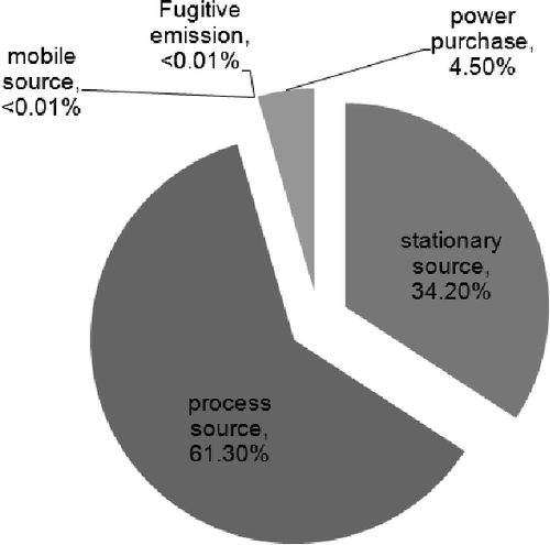
Establishing the GHG inventory of the H plant in Taiwan followed the ISO 14064 standardization procedures, and the inventory is listed in . The overall GHG emissions in 2010 were 4.36 Mt of carbon dioxide equivalent (CO2-eq). Direct GHG emissions (Scope 1) were the largest emission source, accounting for 95.5% of the overall GHG emissions of H plant, followed by energy indirect GHG emissions (Scope 2; 4.50%). The CO2 emission identified was 4.35 Mt CO2-eq, which accounted for 99.8%, as listed in . By the GHG emission sources type classification, it can be seen that the process source emissions were 2.67 Mt CO2-eq, stationary source emissions were 1.5 Mt CO2-eq and power purchase emissions were 0.2 Mt of CO2-eq. shows the GHG emissions from different source types in 2010. The process source emissions accounted for 61.3% of the total GHG emissions of H plant in 2010, with stationary source emission and power purchase emission accounting for 34.2 and 4.5%, respectively.
Table 1. Greenhouse gas emission inventory of H plant in 2010.
Table 2. Emission statistical data by greenhouse gas type.
Emission intensity analysis and comparison
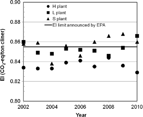
According to the “EPA Early Actions for Carbon Credit of Greenhouse Gases Reduction” regulation of Taiwan, the GHG EI of the clinker production in a cement plant should be lower than the EI limit (0.855 ton CO2-eq/ton clinker) announced by the EPA. This study analyzed the GHG emission intensity of H, L and S cement plants of Taiwan. The analysis results and the standard values announced by EPA are listed and presented in and , respectively. Unfortunately, only one cement plant (H plant) met the regulation. H plant employs an NSP kiln that has superior energy efficiency compared to all conventional kilns (such as vertical shaft kilns, wet kilns, long dry kilns, Lepol kilns and suspension preheater [without precalciner] kilns), and sufficiently reduces the coal utilization and GHG emission. For the cement industry in Taiwan, overall clinker production was about 17 Mt in 2012. The average GHG EI value in Taiwan's cement industry is about 0.917 ton CO2-eq/ton clinker. If the average EI met the EPA limit, the GHG reduction potential is 1.054 Mt per year, which is based on a single year's data for EI and for clinker production.
Table 3. Emission intensity (ton CO2/ton clinker) analysis results (EPA limit = 0.855).
Raw meal calcination test results
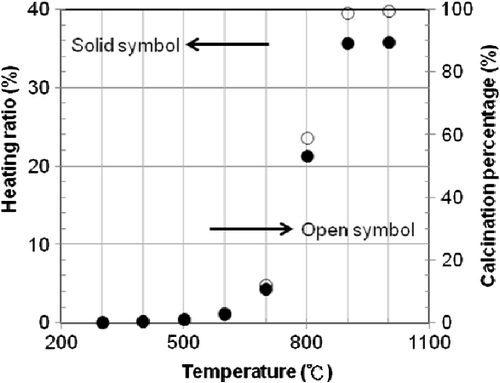
The content analysis results show that each gram of raw meal contained 0.7503 g CaCO3 and 0.0572 g MgCO3. According to the chemical reaction equations, the theoretical calcinations of CaCO3 and MgCO3 are 0.3301 and 0.0299 g CO2, respectively. In other words, the CO2 released (theoretical calcination amount) per gram of raw meal is 0.36 g. The calcination test results of raw meal at different temperatures (300–1000°C) are shown in . The heating ratio is less than 1% during the calcination temperature range from 50 to 300°C. When the calcination temperature approaches 700°C, the heating ratio obviously increases. Besides, reveals that the heating ratio exhibits no significant change when the calcination temperature is at 900–1000°C.
The theoretical calcination amount is placed into EquationEquation (4)(4) to determine the calcination percentage at different calcinated temperatures (300–1000°C); the calculated results are also shown in . There is no obvious change of calcination percentage when the raw meal is calcinated from 300 to 500°C. If the calcination occurs at 600, 700 and 800°C, the calcination percentages are 3.11, 12.12 and 59.19%, respectively. When the calcination reaches 900°C, the calcination percentage is 98.97%. The calcination experiment from 900 to 1000°C is not cost effective because the calcination percentage increased by only 0.42%. Therefore, the major calcination reaction occurs in the 700–900°C temperature range, and accounts for nearly 87% of total CO2 emissions.
Cement process modification
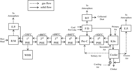
The large amount of CO2 emitted from cement plants is generated by limestone calcination, fossil fuel combustion and raw material comminution (electricity consumption). shows a block flow diagram of the H plant process, which is very similar to what is shown in a 2008 report of the IEA [Citation105], and serves as the base case configuration for the process modification. The raw materials for cement include limestone, clay and sand. After mining, proportioning, crushing, grinding and transporting, the raw meal has the desired fineness and overall chemical composition. Raw material comminution is an electricity-intensive process. The raw meal passes through the preheater, the precalciner and a rotary kiln for clinker production. Clinker production is the most energy-intensive process in the cement industry. There are two processes (wet and dry) for producing clinker, and the dry process is more energy efficient. All cement in Taiwan is produced using the dry process, and all plants employ NSP kilns. The raw materials are preheated using waste heat from the kiln exhaust. The preheated raw meal enters the pre-calciner, where over 98.5% of the CaCO3 and MgCO3 are calcined at the operating temperature of 900°C. The heat of the pre-calciner is supplied from the coal combustion with the tertiary air by the clinker cooler. The heat for the preheater system is derived by contacting the flue gas leaving the kiln at 1400°C, and the heat for the pre-calciner is from the combustion of powder coal fuel burned in the pre-calciner to heat the raw meal from 350 to 840°C.
We proposed a modified process – oxygen calcination – as shown in . An oxygen calciner uses oxygen instead of air, to result in a pure CO2 exhaust stream. A portion of the raw meal (∼10%, which is based on the capacity of the pure oxygen generator) leaving the third preheater stage (this stage was chosen because the significant calcination commences close to 700°C; see ) is diverted and is calcined separately in a diesel fuel burner using oxygen rather than air. This combustion produces an exhaust stream containing far less nitrogen and NOx than would be the case were the diesel to be burned in air, and thus the resulting combustion and calcination CO2 will represent a much higher proportion of the exhaust stream than that from the existing NSP. This CO2-rich exhaust will be more amenable to CO2 compression and removal than the exhaust from the standard NSP circuit would be. Because the total volume of gas will be less, comparatively smaller induced draft (ID) fans, and hence less electricity, will be required. Besides, the volume of raw meal entering the standard pre-calciner will be reduced, anf presumably the fuel combustion by the pre-calciner will also be reduced. The oxygen calcination process is described below.
Figure 5. Schematic diagram of the proposed process integration of the H plant kiln line with a carbon dioxide capture unit.
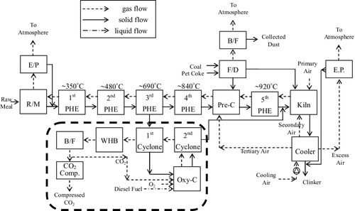
First, part of the preheater raw meal leaving the third preheater (690°C) enters the first cyclone, which is supplied with the heat gases from the second cyclone, to calcine up to 800°C. According to the heating ratio, 21.34% (see ), the CO2 will release about 213.4 kg per ton of raw meal, referring to the mass of raw meal diverted to the oxygen calciner.
Subsequently, the raw meal leaving the first cyclone enters the oxygen calciner system and then utilizes the second cyclone to extend the residence time to allow the raw meal to reach up to 900°C to maximize the calcination. The heating ratio in this process will add 143.4 kg of CO2 per ton of raw meal.
In addition, the high-temperature CO2 stream (750°C) from the top of the first cyclone will enter the waste heat boiler (WHB) for the heat recovery process and steam turbine operation; the temperature will cool down to 350°C.
The fuel of the oxygen calciner system is diesel combusted with the mixing of pure oxygen and recycled CO2 from the waste heat boiler (WHB; 20:80) to generate the high-temperature (about 1000°C) CO2 stream. The raw meal powder formed in the bottom of the second cyclone (900°C) will enter the clinker kiln, and the high-temperature CO2 stream (850°C) from the top of the second cyclone enters into the first cyclone.
Finally, the lower temperature CO2 stream (350°C) from the WHB will pass through a bag filter and flow to the oxygen calciner system and the CO2 compression unit, respectively.
The comparison of oxygen calcination with a calcium-looping process
Calcium-looping pilot unit at the H plant
A schematic diagram of the 1.9-MWh pilot integration of the H plant with the Ca-looping capture unit designed by ITRI, which uses CaO as a regenerated solid sorbent, is shown in . The Ca-looping process is feasible for Taiwan's cement industry due to its high adsorption ability and the abundant limestone resources available in eastern Taiwan. As a result of the deterioration of the CO2 absorption capacity through the carbonation/calcination cycles, fresh CaCO3 needs to be added into the calciner while the same amount of spent sorbents (CaO) on a molar basis are removed [Citation11]. The main parts of the pilot plant are the carbonation system, the calcination system and the recycling system [Citation18].
Figure 6. Schematic diagram of the process integration of the H plant kiln line with a calcium-looping capture unit.
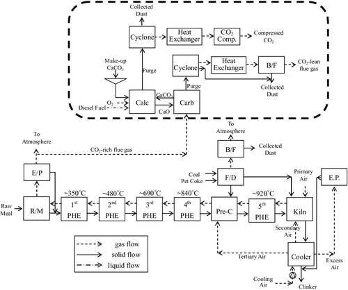
The exhaust flow rate from the stack of the cement plant is about 558,000 Nm3/h, equivalent to 695.1 ton/h at temperature of 105°C. A fan is used to draw out the flue gas and then pump it into the windbox of the carbonator. The maximum flow rate introduced into the calciner is 2083 m3/h, which is equivalent to 3.1 ton/h at a temperature of 70°C. In summary, the 1.9-MWh pilot integration of the H plant with a Ca-looping capture unit captures CO2 at a rate of about 1.0 ton/h. Unfortunately, the pilot plant with a Ca-looping capture unit has to utilize extra energy to capture the CO2. The causes of the extra CO2 emissions due to the extra energy utilization are evaluated below:
The electrical power consumption of the Ca-looping capture unit resulted in 80 kg of CO2 emissions;
The CO2 emission from the electrical power consumption of the O2 generation system was 73 kg;
The electricity utilized in the CO2 liquefaction was equivalent to CO2 emissions of 73 kg;
Diesel oil consumption produced CO2 emissions of about 43 kg;
Therefore, the total extra CO2 emissions amounted to about 269 kg for the pilot plant integration of the H plant with a Ca-looping capture unit in order to capture CO2 at 1.0 ton/h.
Furthermore, other difficulties and challenges must be overcome:
The calciner in the pilot plant, a rotary kiln, resulted in the stocks piling up in the bottom. The drawbacks to this include: gas/solid contact area reduction, slower heat transfer, larger resistance and the fact that increasing the partial pressure of CO2 requires higher temperature to calcinate the CaCO3;
The CO2 absorption capacity of the CaCO3 in the Ca-looping capture unit lasted through about 10 carbonation/calcination cycles; fresh CaCO3 had to be added into the calciner while the same amount of spent sorbents (CaO) was removed. The temperature of the deteriorated sorbents discharged was still high, about 600°C, resulting in a heat loss without waste heat recovery;
In the carbonation system, the carbonator was packed with a mixture of deteriorated sorbents and the CaCO3 removed from the carbonator. Therefore, the CO2 absorption capacity of the CaCO3 remains uncertain and needs to be reduced;
However, the coal consumption of the rotary kiln was not reduced for the process integration of the H plant with a Ca-looping capture unit.
Advantages of oxygen calcination over calcium looping
Although the Ca-looping technology is a promising technology for carbon capture from industrial sources, there are several issues that need to be addressed before its large-scale application, including some difficulties and challenges mentioned in the section on the “Ca-looping pilot unit at the H plant.” The comparison for CO2 capture by Ca-looping and oxygen calcination processes is tabulated in . The characteristics of the oxygen calcination process proposed in this paper can be summarized as follows:
The fuel for the oxygen calcination system is diesel, rather than coal, and can reduce NOx emissions due to the oxygen-rich air;
All of the raw meal powder formed in the bottom of the second cyclone enters the rotary kiln and reduces the heat loading of the (regular) calciner to reduce the coal consumption;
The first cyclone to the oxygen combustion system has no pipeline corrosion since the raw meal is a sulfur-free component;
The investment and operating costs of the modified process proposed in this paper are much less than the process integration of the H plant with a Ca-looping capture unit;
The high-temperature CO2 stream from the top of the first cyclone enters the WHB and generates steam in combination with the waste heat cogeneration system of the cement plant;
The vertical oxygen combustion system combined with the cyclone substantially increases the heat-exchange area, reduces the difficulty of CaCO3 calcination and increases the calcination percentage;
There is no need to add fresh CaCO3 and discharge the deteriorated sorbents; consequently, there is no extra heat loss in the modified process;
The raw meal leaving the third preheater enters the first cyclone; the flue gas recovery will not induce system loading and can sufficiently recover the waste heat of the raw meal;
An oxygen calciner is better than just substituting oxygen for the tertiary air in the regular NSP calciner. The addition of an oxygen calciner causes minimal disruption to normal plant operations. Substituting oxygen for the tertiary air in the regular NSP calciner is not an option owing to the large amount of pure oxygen demand.
Table 4. The comparison for carbon dioxide capture by calcium-looping and oxygen calcination processes.
Conclusion
Taiwan must eventually conform to the Kyoto Protocol, even though it was not one of the signatories. Preparations are required in order to reduce the adverse effects to some sectors of the economy and some businesses. GHG inventory of a cement plant (H plant) in Taiwan, GHG emission intensity (EI) analysis, the raw meal decomposition test and a modified process for carbon dioxide capture were evaluated in this study. The GHG inventory analysis results show that direct greenhouse gas emissions (Scope 1) are the largest emission source, accounting for 95.5% of the overall GHG emissions of H plant. The EI analysis results of Taiwan's cement plants show that only one cement plant (H plant) met the standard value announced by the EPA. Obviously, there is much GHG reduction potential to exploit, and much effort is required. According to the calcination test, the calcination percentages are: 3.11, 12.12 and 59.19%, respectively, at 600, 700 and 800°C calcination temperature. The results also show that the calcination percentage is 98.97% if calcination reaches 900°C. In other words, the major calcination reaction happened in the 700–900°C temperature range, and accounted for nearly 87% of total CO2 emissions. The flue gas composition consists of CO, CO2, N2, NOX, O2 and SOX that cannot be directly purified by the CO2 compression system. Therefore, we proposed a modified and feasible process as a baseline case for simulating options of GHG reduction in the cement industry. The CO2 reduction potential will be about 356.8 kg per ton of raw meal.
Conflict of interest
The authors declare that they have no conflicts of interest.
Acknowledgements
Financial support from the National Science Council (NSC), ROC (Taiwan), through Grant NSC 101-2622-E-197-006-CC3, is gratefully acknowledged. The anonymous reviewers are also appreciated for their comments.
Additional information
Funding
References
- Kramer KJ, Moll HC, Nonhebel S, Wilting HC. Greenhouse gas emissions related to Dutch food consumption. Energy Policy 27(4), 203–216 (1999).
- Lin HC, Chan DYL, Lin WC, Hsu CH, Hong GB. Status of energy conservation in Taiwan's pulp and paper industry. Energy 73, 680–685 (2014).
- Hasanbeigi A, Price L, Lin E. Emerging energy-efficiency and CO2 emission-reduction technologies for cement and concrete production: a technical review. Renew. Sustain. Energy Rev. 16(8), 6220–6238 (2012).
- Dong RF, Lu HF, Yu YS, Zhang ZX. A feasible process for simultaneous removal of CO2, SO2 and NOx in the cement industry by NH3 scrubbing. Appl. Energy 97, 185–191 (2012).
- Hassan SMN. Techno-economic study of CO2 capture process for cement plants [MSc thesis]. Chemical Engineering, University of Waterloo, Canada (2005).
- Pan X, Clodic D, Toubassy J. CO2 capture by antisublimation process and its techincal economic analysis. Greenh. Gases Sci. Technol. 3(1), 8–20 (2013).
- European Cement Research Academy (ECRA). Technical Report: (TR-ECRA-106/2009), ECRA CCS Project-Report about Phase II, (2009) 40476, Duesseldorf, Germany.
- Rodriguez N, Murillo R, Abanades JC. CO2 capture from cement plants using oxyfired precalcination and/or calcium looping. Environ. Sci. Technol. 46(4), 2460–2466 (2012).
- Stallmann O. Integrated carbon dioxide capture for cement plants. Patent Publication No. CA2844795A1, CN103717290A,US20140161696,WO2013024340A1, Alstom Technology Ltd. (2013).
- Rodriguez N, Murillo R, Alonso M, Martinez I, Grasa G, Abanades JC. Analysis of a process for capturing the CO2 resulting for pre-calcination of limestone in a cement plant. Ind. Eng. Chem. Res. 50(4), 2126–2132 (2011).
- Ozcan DC, Ahn H, Brandani S. Process integration of a Ca-looping carbon capture process in a cement plant. Int. J. Greenh. Gas Control 19, 530–540 (2013).
- Shimizu T, Hirama T, Hosoda H, Kitano K, Inagaki M, Tejima K. A twin fluid-bed reactor for removal of CO2 from combustion processes. Chem. Eng. Res. Des. 77(1), 62–68 (1999).
- Kremer J, Galloy A, Ströhle J, Epple B. Continuous CO2 capture in a 1-MWth carbonate looping pilot plant. Chem. Eng. Technol. 36(9), 1518–1524 (2013).
- Arias B, Diego ME, Abanades JC, Lorenzo M, Diaz L, Martinez D, Alvarez J, Sanchez-Biezma A. Demonstration of steady state CO2 capture in a 1.7-MWth calcium looping pilot. Int. J. Greenh. Gas Control 18, 237–245 (2013).
- Plötz S, Bayrak A, Galloy A, Kremer J, Orth M, Wieczorek M, Ströhle J, Epple B. First carbonate looping experiments with a 1-MWth test facility consisting of two interconnected CFBs. In: 21st International Conference on Fluidized Bed Combustion, Naples, Italy, 421–428 (2012). Technische Universität Darmstadt, Fachbereich Maschinenbau.
- Dieter H, Hawthorne C, Bidwe AR, Zieba M, Scheffknecht G. The 200-kWth dual fluidized bed calcium looping pilot plant for efficient CO2 capture: plant operating experiences and results. In: Proceeding of the 21st International Conference on Fluidized Bed Combustion, Naples, Italy 397–404 (2012). Technische Universität Darmstadt, Fachbereich Maschinenbau.
- Huang CM, Hsu HW, Liu WH, Cheng JY, Chen WC, Wen TW, Chen W. Development of post-combustion CO2 capture with CaO/CaCO3 looping in a bench scale plant. Energy Procedia 4, 1268–1275 (2011).
- Chang MH, Chen WC, Huang CM, Liu WH, Chou YC, Chang WC, Chen W, Cheng JY, Huang KE, Hsu HW. Design and experimental testing of a 1.9MWth calcium looping pilot plant. Energy Procedia 63, 2100–2108 (2014).
- Desrosieres A. The Politics of Large Numbers: A History of Statistical Reasoning. Harvard University Press, London, UK (1998).
- Talbot D, Boiral O. Can we trust corporates GHG inventories? An investigation among Canada's large final emitters. Energy Policy 63, 1075–1085 (2013).
Websites
- Environmental Protection Administration (EPA), ROC (Taiwan). 2014 Republic of China (Taiwan) National Inventory Report (2014). http://unfccc.saveoursky.org.tw/2014nir/uploads/00_2014nir.pdf
- IEA (International Energy Agency). CO2 emissions from fuel combustion. Paris, France (2006). www.iea.org
- IEA Clean Coal Center. CO2 abatement in the cement industry (2011). www.iea-coal.org/documents/82745/8189/CO2-abatement-in-the-cement-industry,-CCC/184
- Environmental Protection Administration Executive Yuan (EPAEY). ROC (Taiwan). http://estc10.estc.tw/ghgenglish/
- IEA (International Energy Agency). CO2 capture in the cement industry, July 2008/3 (2008). http://ieaghg.org/docs/General_Docs/Reports/2008-3.pdf
Appendix 1.
Abbreviations
| C | = | the yearly clinker production |
| CP | = | calcination percentage |
| EI | = | the GHG emission intensity |
| EPA | = | the Environmental Protection Administration of Taiwan |
| GEclinker | = | the GHG emission of clinker process, including the comminution of raw materials and the burning of clinkers (excluding non kiln fuel of mining and quarrying) |
| HR | = | The heating ratio |
| Mt | = | million metric tons |
| NSP | = | new suspension preheaters or called preheater-precalciner kiln |
| TGE | = | the total GHG emission of clinker production process |
| TPE | = | total purchased electricity. |
| VCS | = | Voluntary Carbon Standards |
| WHB | = | the waste heat boiler |

