Abstract
For the analysis of transient two-phase flows in nuclear reactor components, a three-dimensional thermal hydraulics code, named CUPID, has been being developed. We simulated the downcomer boiling experiment (DOBO) experiment in two-dimensions using the CUPID code to evaluate its two-phase flow models and verify its applicability to the downcomer boiling analysis. The simulation result showed that it can reproduce the important characteristics of the downcomer boiling, such as a flow pattern change from a bubbly flow to churn and mist flows and a circulation of liquid accelerated by bubbles. The two-phase flow models that require further improvement were identified as well for an enhanced prediction of the downcomer boiling.
1. Introduction
The need for a multi-dimensional analysis of the thermal hydraulic phenomena in a component of a nuclear reactor is increasing with the advanced design features, such as a direct vessel injection (DVI) system, a gravity-driven safety injection system, and a passive secondary cooling system. For example, in an advanced pressurized water reactor, multi-dimensional phenomena inside the reactor vessel during a postulated loss of coolant accident have become major technical issues for consideration [Citation1]. These include the emergency core coolant (ECC) bypass of a DVI system and a downcomer boiling during the reflood phase of a large-break loss-of-coolant accident (LBLOCA). These phenomena are characterized by the combination of a boiling due to a downcomer wall heat transfer, multi-dimensional counter-current flow, lateral motion of bubbles and droplets, flow regime change, bulk condensation, phase separation, etc. These features require more detailed analysis with enhanced accuracy because of the complicated multi-dimensional effects. Motivated by these issues, the development of a numerical solver for a multi-dimensional thermal hydraulic analysis code, named CUPID [Citation2], is in progress at Korea Atomic Energy Research Institute (KAERI). The objective of the development is to support a resolution for the thermal hydraulic issues regarding the transient multi-dimensional two-phase flow which can arise in an advanced light water reactor.
The numerical solver and two-phase flow models of the CUPID code have been established as a standalone code at first. They have been verified against standard conceptual problems of single- and two-phase flows and validated for thermal–hydraulic experiments in our previous studies [Citation3–Citation5]. The assessment strategy for the future verification and validation was outlined in Jeong et al. [Citation2]. Recently, the CUPID code was coupled with a system analysis code, MARS [Citation6] and a three-dimensional kinetics code, MASTER [Citation7], which is expected to provide the advanced multi-scale and multi-physics calculations for many safety-related issues of the light water reactors [Citation8]. The verification results for these multi-scale and multi-physics calculations showed that coupled calculations using the CUPID code can be one of its major applications in the future.
As a multi-scale analysis application, it is being considered to use the CUPID code, coupled with MARS, for the simulation of the downcomer boiling phenomena. They were reported to happen in the downcomer of a nuclear reactor vessel during the reflood phase of a postulated loss of coolant accident [Citation9]. The stored energy release from the reactor vessel to the ECC inside the downcomer causes the boiling on the wall, and it can reduce the hydraulic head of the accumulated water in the downcomer, which is the driving force of water reflooding to the reactor core. These phenomena have been considered as a technical issue of an advanced light water reactor because it is concerned with the core cooling capability of a safety injection system. Due to the large hydraulic diameter of the downcomer and the low velocity of the downward liquid, it was reported that the boiling phenomena are apparently multi-dimensional [Citation9], which are not reproducible by the one-dimensional approach of existing system codes. As an attempt to analyze these phenomena in a multi-scale analysis frame, the CUPID code has been proposed to simulate the downcomer region of the reactor vessel where the multi-dimensional phenomena are important while the MARS code covers the remaining parts of the reactor. Prior to this coupled simulation for the downcomer boiling, it is required to validate the CUPID code and its two-phase flow models against available downcomer boiling data.
In this study, the downcomer boiling experiment (DOBO) [Citation9] was simulated using the CUPID code. The test was performed at KAERI to understand the boiling inside the downcomer and provide the data for the code validation. The purpose of this study is to assess the two-phase flow models of the CUPID code for the analysis of downcomer boiling. The reproduction of the important characteristics of the boiling phenomena in a large duct using the code was of special interest. In particular, it was reported that not only a bubbly flow but also some other flow patterns and the transitions between them appear in the downcomer boiling such as a churn flow, a mist flow and so on. The two-phase flow models for these flow patterns and transitions have not been assessed sufficiently using either a state-of-the-art thermal hydraulic analysis code or a computational fluid dynamics code. This assessment was aimed to verify the applicability of the two-phase flow models that CUIPD incorporated and identify their limitations for the downcomer boiling analysis.
2. Two-phase flow models
The CUPID code adopts the two-fluid model for two-phase flows [Citation2]. In the two-fluid model, the mass, energy, and momentum equations for liquid and vapor phases are established separately, and then, they are linked by the interfacial mass, momentum, and energy transfer models. The governing equations and the numerical methods are described in Jeong et al. [Citation2]. For a mathematical closure, the constitutive relations for the interfacial momentum transfer, the interfacial heat transfer, and the wall heat partitioning are necessary and these are summarized in this chapter.
2.1. Inter-phase topology map
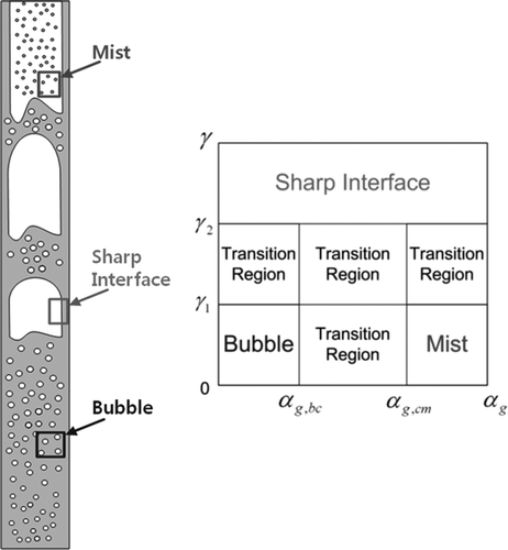
In a two-fluid model, the mass, momentum and energy transfers between phases depend on the shape of their interfaces. The conventional system and component analysis codes use flow regime maps to model the interface structure. The traditional flow regime concept, however, is not applicable to open medium analyses because every cell needs to include a wall boundary for the cross sectional average of a flow parameter. To address this issue, CFD-BWR code, built on the foundation of STAR-CD, proposed an inter-phase surface topology map recently [Citation10,Citation11]. In their works, simulations have been conducted not only for dispersed flows but also for flows involving a local sharp interface such as slug and annular mist flows. According to their approach, the three main types of local inter-phase surface topologies are defined and transition regions are set for the intermediate topologies. Three main topologies are a bubbly flow topology, a mist flow topology and a sharp interface topology as shown in . The transitional topologies cover the overlapping regions of two or three main topologies. The topology in each mesh cell is determined by two parameters, a void fraction (αg ) and a gradient of the void fraction (γ = δ|∇αg |). Tentner et al. [Citation12,Citation13], Ioilev et al. [Citation14] and Ustinenko et al. [Citation15] have established a significant progress to verify and validate this approach. The inter-phase topology concept proposed by Tentner et al. [Citation13] was employed in the CUPID code to deal with the flow pattern change from the bubbly flow to the churn and mist flow. The transition criteria of the void fraction and the void fraction difference and the definition of the characteristic length (δ) are
where
and
Once a local topology is determined for each cell, the interfacial area and interfacial transfer models, thereafter, are defined depending on the topology of the cell.
In the following sub-sections, the two-phase flow models for the present calculation are listed. Those for the interface topology, however, were omitted because it merely appeared in the top region of the test channel which is not of special interest for the downcomer boiling.
2.2. Interfacial area concentration
The interfacial area concentration is defined by:
For bubble topology,
where
,
,
,
and
is the frictional pressure drop calculated with Lockhart–Martinelli's correlation [Citation18].
For mist topology [Citation17],
2.3. Interfacial momentum transfer
The interfacial momentum transfer term,
includes the interfacial drag, the momentum exchange due to the phase change at the interface and wall, and various non-drag forces such as the virtual mass force, lift force, wall lubrication force and turbulent dispersion force.
is written as:
The interfacial drag force terms in the momentum equations can be expressed as:
The interfacial drag force in the transition topology was calculated from the linear interpolation between the values of two different topologies. Interfacial drag coefficients used in the present calculation are:
The current CUPID code has four non-drag forces: the virtual mass force, lift force, wall lubrication force and turbulent dispersion force,
The virtual mass force was applied for all topologies and the other forces were considered when either bubble topology or churn topology was identified. The definitions of each term and the implemented models for these are presented in [Citation19–Citation22].
Table 1. Interfacial non-drag force models for CUPID.
2.4. Interfacial mass and heat transfer
The interfacial mass and heat transfer terms are written as;
where (h
gi
,h
li
) = (h
g,sat,h
l
) if
and (h
gi
,h
li
) = (h
g
,h
l,sat) if Γ < 0. For the interfacial heat transfer coefficients for the dispersed topologies, the Ranz and Marshall correlation [Citation23] was adopted. During flashing, where T
l
> T
sat, the liquid-side heat transfer factor is calculated using the following approximate model:
A superheated liquid quickly returns back to its saturated condition by this model. The value 106 was referred to in Spore et al. [Citation24].
The wall boiling on a heated surface is simulated by a wall heat flux partitioning model. In this model, the mechanisms of a heat transfer from the wall to a two-phase flow consist of the surface quenching (qq ), evaporation (q e ) and single phase convections (q w/k and q wgc ). The wall-to-liquid heat transfer (q wl ) is the sum of the q q and q w/c . It is assumed that the direct contact heat transfer between droplets and the wall is negligible so that a gas phase convective heat transfer is merely considered for the mist topology (q wgc = q wg ). Then, an equation of the heat flux conservation on a heated surface is
The closure relations for this heat flux partitioning were listed in Bae [Citation25].
2.5. Turbulence modeling
In the CUPID, two models are available for the turbulent shear stress; one is the mixing length model and the other one is the standard k-ϵ model. In the present study, the mixing length model was used with the bubble induced turbulence terms, which were proposed by Michiyochi and Serizawa [Citation26] because the k-ϵ model for a churn and mist flow region where the continuous phase is changed from liquid to vapor has not been implemented into the CUPID code. The enhancement of the k-ϵ model for these high void fraction conditions is in progress. Meanwhile, in a two-phase flow, it was reported that the existence of bubbles on the wall boundary layer has a significant influence on the velocity profile nearby the wall. To account for this effect, the two-phase wall function proposed by Yun et al. [Citation27] was implemented for the boiling flow simulation.
3. DOBO facility and test result
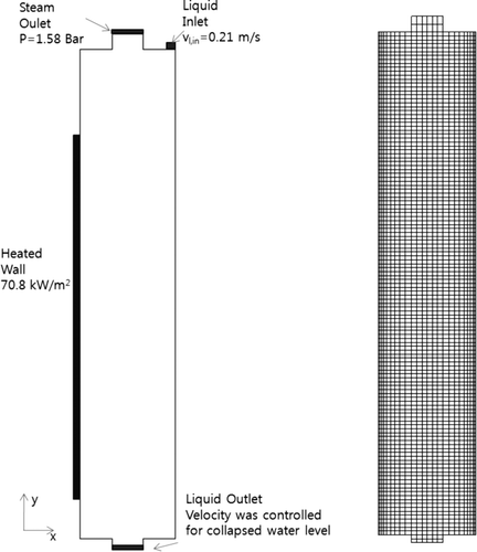
The DOBO test facility was designed to simulate the downcomer boiling phenomena that may occur in the lower downcomer region below a cold leg during the reflood phase of a postulated LBLOCA [Citation9]. The DOBO facility consists of a test section, a condenser, a heat exchanger, a drain pump, a mixing tank, a pre-heater and an injection pump, as shown in (a). The test section has rectangular duct geometry and its dimensions are 6.4 m high, 0.25 m wide, and 0.30 m deep. The height and width are the same with the APR1400 downcomer, but the circumference is reduced to 47.08-fold. One among four side walls of the test section incorporates 207 cartridge heaters inside it to simulate the stored energy release from the reactor vessel wall. The heated region starts 0.3 m above the bottom of the test section, and ends 1.0 m below its top. (b) indicates the schematic diagram of the test section. The DOBO test was performed with four different heat fluxes; DOBO-R2-1 test case conducted with 70.8 kW/m2 was selected for the current simulation because it is the closest value to the predicted heat flux of the reflood phase.
Figure 2. Inter-phase surface topology concept: (a) schematic of the test loop and (b) schematic of the test section.
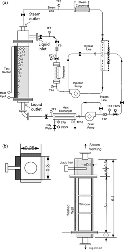
In an accident condition, the emergency core cooling water flows down into the downcomer from the elevation of the ECC injection nozzle to the lower plenum. Thus, the downcomer boiling happens with the downward liquid flow and, then, the counter-current flow appears between the downward liquid and upward bubbles near the reactor vessel wall. The liquid inlet, therefore, was located at the upper region of the test section as indicated in (b). The injected liquid impinges on the test section wall and flows downward forming a liquid film. The inlet flow rate was 1.33 kg/s in DOBO-R2-1 test. Due to the heat released from the heated wall, boiling occurs in the test section. The generated steam flows out from the test section through the outlet, where the pressure was maintained at 1.6 bars. The accumulated liquid formed a free surface inside the channel and the water level was maintained at 5.7 m by controlling the liquid outlet flow rate located at the bottom of the test section.
The major measuring parameters of the DOBO test are the void fraction, gas velocity, liquid velocity, water temperature and pressure along the elevation. The details of the measurement instrumentations and the results were reported in Yun et al. [Citation9]. (a) shows the experimental results of the local void fraction at different heights, and each point on the graph represents the averaged value along the depth direction of the test section. The void fraction distributions at the elevations, 1.53 m and 2.53 m, indicate typical wall peaking profiles that the maxima of the void fraction appeared on the heated wall. Then, the void fraction decreases gradually as the distance from the heated wall increases. Above the elevation 3.53 m, however, bubbles began to move to the center region of the channel and the void fraction profiles of a core peaking were obtained. The maximum value of the void fraction at a horizontal cross-section appeared at the center of the channel.
Figure 3. DOBO experimental results: (a) void fraction, (b) liquid velocity, and (c) visual observation.
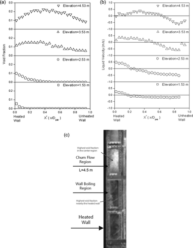
(b) shows the experimental results of the local liquid velocity measured with local bidirectional flow tubes. In the measurement, the liquid velocity was positive nearby the heated wall where higher void fraction appeared and negative in the other part. This result shows that the liquid was accelerated by the bubbles resided on the heated wall and then the liquid moved downward in the other region where no bubble existed for the conservation of the mass at the horizontal cross-section. Since the liquid flow rate of the DOBO test is very small, approximately 0.0254 m/s in the cross-sectional average, the natural circulation accelerated by the wall boiling was found to be dominant in the test section. (c) shows the experimental observation result of the downcomer boiling phenomena. Consistent with the experimental measurement results, the bubbles mainly appeared on the heated wall at low elevation, but they began to move toward the center region along the elevation, and finally the flow pattern change from the bubbly flow to the churn flow started at the higher elevation than 4.5 m.
In the experimental result, it was found that the particular characteristics of the downcomer boiling phenomena involve the core peaking of the void fraction profile, the flow pattern change from the wall boiling flow to the churn and mist flow, and the bubble accelerated natural circulation of the liquid. Therefore, the present simulation for the DOBO test was mainly focused on whether these can be reproduced by the CUPID code appropriately.
4. The results of the CUPID calculation
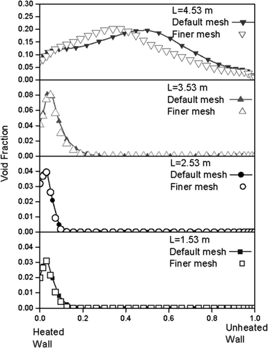
shows the boundary conditions of the calculation and the computation mesh. The test section was modeled in two-dimensions with the symmetric boundary condition in order to save computational time and to test two-phase flow models conveniently. The experimental results averaged along the depth direction justified this simplification because it showed the overall flow behavior such as the void fraction profile and its transition, the circulation of the liquid flow, etc. are well preserved in the averaged quantities. A total of 3096 (24 × 122 for the duct) cells were used for the present calculation. shows the mesh convergence results for void fraction profiles and reasonable convergence was achieved between the default mesh and a finer one in the radial direction (36 × 122). As same with the experimental procedure, the constant heat flux for the heated wall, the constant pressure for the steam outlet, constant velocity for the liquid inlet conditions were imposed. The liquid outlet flow rate was controlled to maintain the collapsed water level in the test section at 5.7 m.
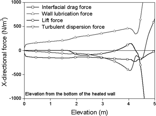
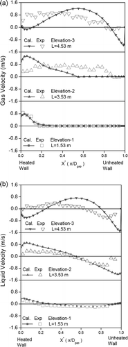
(a) shows the calculation result of the void fraction with the aforementioned two-phase flow models. The void fraction distributions are compared in (b) at three different elevations (1.53 m, 3.53 m, and 4.53 m) between the experimental data and the simulation results. At the elevation of 1.53 m (Elevation-1), the wall peaking of the void fraction profiles was obtained in both the experiment and the simulation. Different from the void fraction of the experimental data which showed the monotonic decrease along the x-direction, however, that of the calculation increases near the heated wall and then decreases gradually. This is mainly considered due to the effect of the large wall lubrication force at the heated wall as shown in . The wall lubrication force acting in the positive direction of the x-axis at this elevation was larger than other forces, and consequently the bubbles generated on the heated wall migrated toward the center of the channel in the calculation. A sensitivity study with various parameters of the x-directional forces was performed, and it was found that a smaller bubble diameter at this elevation can enhance the prediction of the void fraction profile. Since there is no available measurement result for the bubble size, however, it is difficult to validate the bubble diameter model and clarify the exact reason of the difference. Further efforts are needed in both experiment and calculation to draw the bubble diameter information from the test and validate the applicability of the model to the downcomer boiling. Other than this difference, the overall void fraction profile at Elevation-1 was reasonably well captured by CUPID.
Figure 6. CUPID calculation result: (a) void fraction distribution, (b) comparison with the experimental data.
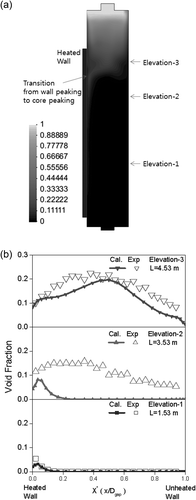
At the elevation of 3.53 m (Elevation-2), a significant difference in void fraction profile was found between the experiment and the calculation. In the experiment, more bubbles were found in the center region of the channel and the core peaking profile of the void fraction was observed. In the calculation, however, the transition from the wall peaking to the core peaking had not yet been started and CUPID predicted a similar profile with that of Eleveation-1. The cross-section averaged void fraction was under-predicted as well at this elevation as shown in . The main reason for this is supposedly due to the over-prediction of the gas and liquid velocities near the heated wall as shown in . It lowered the predicted void fraction values compared to the experimental data and the underestimation of the bubble size could follow. Since the bubble size was not large enough to change the direction of the lift force, the bubbles kept residing on the heated wall. The lift force is known to push the bubbles toward the wall if their diameter is smaller than a certain value and vice versa.
The core peaking of the void fraction profile was reasonably well reproduced by the CUPID code at the elevation of 4.53 m (Elevation-3). As shown in (a), the transition from the wall peaking to the core peaking started at approximately 4.2 m, and afterward the location of the void fraction peak moved to the center of the channel. The predicted bubble diameter increased with void fraction along the elevation and became larger than the criterion for the lift force direction. The lift force became positive subsequently as shown in and then started acting toward the central direction. Finally, the peak location of the void fraction began to move toward the core region when the sum of the lift force and the wall lubrication force was larger than that of the others.
Furthermore, as observed in the experiment, the churn flow was identified above Elevation-3 in (a), which has a very high void fraction in the core and a low void fraction on the wall. Near the top of the test section, a mist flow appeared above the free surface, where the void fraction was higher than 0.95. This calculation result of the void fraction distribution showed that the overall behavior of the two phases can be reproduced reasonably by the CUPID code with the present models. However, further improvement of the models is required to enhance the calculation results, such as too large value of the wall lubrication force at Elevation-1, under-predicted void fraction at Elevation-2, and the late transition of the wall peaking to core peaking.
(a) indicates the y-directional gas velocities compared between the calculation and the experiment. At Elevation-1 and Elevation-3 where CUPID predicted void fraction profiles correspondent well with the experiment, the gas velocities were reasonably predicted as well. However, at Elevation-2, considerable differences in the predicted gas velocity were found compared to the experiment as in the case of the void fraction. While the highest velocities were found at the center of the channel in the experiment, the maximum velocity in the calculation appeared near the wall where the void fraction was high. (b) compares the computational and the experimental results of the y-directional liquid velocities. The circulation of the liquid, the upward flow along the heated wall and the downward flow in the other side, was properly reproduced by the CUPID code. The predicted liquid velocity profile at the wall boiling region (Elevation-1) was in good agreement with the experimental data. In the other elevations, however, it over-predicted the upward velocity and under-predicted the downward one. This implies that the natural circulation of the liquid was accelerated excessively by bubbles in the calculation. This difference seems to be caused by the interfacial drag models and the bubble-induced turbulence models. The implemented models for the interfacial drag and the bubble-induced turbulence were proposed with spherical shape bubbles. In the downcomer boiling, however, the shape of the bubble is not spherical in some region due to high void fraction and low liquid velocity condition. The models applicable to cap bubbles and churn flow are required to improve the calculation result.
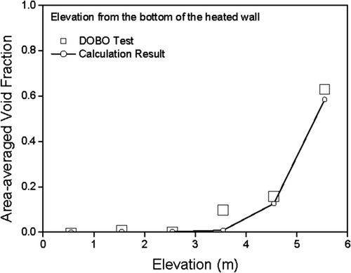
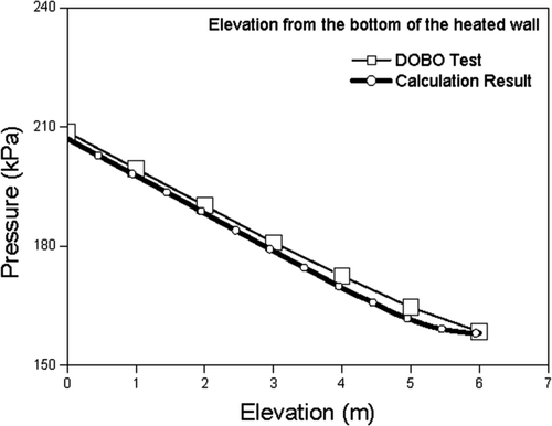
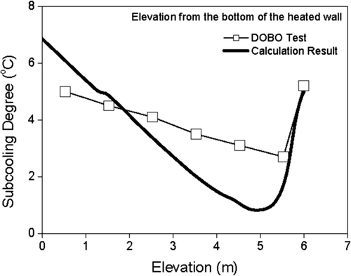
In the downcomer boiling analysis, some averaged propertiessuch as the averaged void fraction, pressure and liquid subcooling play very important role concerned with the reactor core cooling. The first two parameters are related to the hydraulic head of the accumulated water, which is the driving force of water reflooding and the latter one is connected to the cooling capability of the ECC. For this reason, the averaged properties were compared between the calculation and the experiment in , 10 and 11. CUPID predicted the averaged void fraction and pressure appropriately except the void fraction at 3.53 m. At this elevation, CUPID under-predicted the void fraction as discussed above with the local void fraction profile. The maximum difference of the pressure between the predicted and measured ones was less than 2%. Meanwhile, the rate of decrease in liquid subcooling along the elevation was higher in the calculation than the experimental data as shown in . This result showed that the calculated liquid temperature was over-predicted in the elevation higher than 2.0 m and vice versa. It was supposed that the over-predicted liquid circulation enhanced the thermal mixing of the liquid inside the test channel and it reduced the predicted temperature difference between the bottom and top regions. The maximum difference of the liquid subcooling was 2°C between the calculation and the experiment.
5. Conclusion
The multi-dimensional thermal hydraulics code, CUPID, has been developed for realistic simulation of transient two-phase flows in nuclear reactor components. In the present article, the physical models and correlations that were employed in the code were introduced and a simulation was performed for the DOBO test facility in order to assess the two-phase flow models. The result showed that it can reproduce the typical characteristics of the downcomer boiling qualitatively such as the core peaking of the void fraction profile, the flow pattern change from the bubbly flow to the churn and mist flows and the bubble accelerated natural circulation of the water. However, further improvements of the models are required to enhance the discrepancies in the void fraction and velocity distributions between the experiment and the calculation such as too large value of the wall lubrication force at the lower elevation, the under-predicted void fraction in the mid-elevation, the late transition of the wall peaking to core peaking and the over-predicted natural circulation velocities. As an effort for these, the two-phase flow models for non-spherical bubbles including the interfacial drag coefficient and the bubble-induced turbulence will be tested in our future works.
Nomenclature
| A i | = |
Interfacial area concentration |
| C | = |
Drag coefficient |
| D | = |
Diameter |
| E o | = |
Eotvos number |
| F | = |
Interfacial force term |
| H | = |
Interfacial heat transfer coefficient |
| j | = |
Superficial velocity |
| L | = |
Elevation |
| N | = |
Surface normal vector at a cell face |
| Q | = |
Interfacial heat transfer term |
| q | = |
Wall heat transfer term |
| q″ | = |
Wall heat flux |
| Re | = |
Reynolds number |
| Sf | = |
Face area between cells |
| V | = |
Cell volume |
| x | = |
Distance from the heated wall |
| = |
Greek Letter | |
| α | = |
Volume fraction |
| ϵ | = |
Energy dissipation rate per unit mass |
| δ | = |
Characteristic length |
| Γ | = |
Vapor generation rate |
| μ | = |
Dynamic viscosity |
| v | = |
Kinematic viscosity |
| = |
Subscripts | |
| bc | = |
Bubble-churn transition |
| c | = |
Continuous phase |
| cm | = |
Churn-mist transition |
| f | = |
Cell face |
| f | = |
Friction |
| g | = |
Gas |
| i | = |
Interface |
| k | = |
Gas, liquid or droplet |
| l | = |
Liquid |
| lift | = |
Lift |
| m | = |
Mixture |
| nd | = |
Non-drag |
| sat | = |
Saturation |
| td | = |
Turbulent dispersion |
| v | = |
Vapor |
| vm | = |
Virtual mass |
| wall | = |
Wall |
| wl | = |
Wall lubrication |
Acknowledgments
This work was supported by Nuclear Research & Development Program of the NRF (National Research Foundation of Korea) grant funded by the MEST (Ministry of Education, Science and Technology) of the Korean government (Grant code: M20702040002-08M0204-00210).
References
- Song , C.-H. , Baek , W. P. , Chung , M. K. and Park , J. K. Multi-Dimensional Thermal Hydraulic Phenomena in Advanced Nuclear Reactor Systems: Current Status and Perspectives of R&D Program in KAERI . Proceedings of NURETH-10 . October . pp. 5 – 9 .
- Jeong , J. J. , Yoon , H. Y. , Park , I. K. and Cho , H. K. 2010 . The CUPID code development and assessment strategy . Nucl. Eng. Technol , 42 : 636 – 655 .
- Yoon , H. Y. , Park , I. K. , Lee , Y. J. and Jeong , J. J. 2009 . An unstructured SMAC algorithm for thermal non-equilibrium two-phase flows . Int. Commun. Heat Mass Transf , 36 : 16 – 24 .
- Park , I. K. , Yoon , H. Y. , Jeong , J. J. , Euh , D. J. and Cho , H. K. An Implementation of the Interfacial Area Transport Equation into the CUPID Code . Proceedings of NUTHOS-8 . October . pp. 10 – 14 .
- Jeong , J. J. , Yoon , H. Y. , Park , I. K. , Cho , H. K. and Lee , H. D. 2010 . Development and preliminary assessment of a three-dimensional thermal hydraulics code, CUPID . Nucl. Eng Technol , 42 : 279 – 296 .
- Jeong , J. J. , Ha , K. S. , Chung , B. D. and Lee , W. J. 1999 . Development of a multi-dimensional thermal-hydraulic system code, MARS 1.3.1 . Ann. Nucl. Energy , 26 : 1611 – 1642 .
- Joo , H. G. , Jeong , J. J. , Cho , B. O. , Lee , W. J. and Zee , S. Q. 2003 . Analysis of the OECD MSLB benchmark problem using the refined core thermal-hydraulic nodalization feature of the MARS/MASTER code . Nucl. Technol , 142 : 166 – 179 .
- Lee , J. R. , Cho , H. K. and Jeong , J. J. Coupled Simulation of Component Thermal Hydraulics and Neutron Kinetics for A Nuclear Reactor Core with CUPID and MASTER . Proceedings of KNS Autumn Meeting . October . pp. 21 – 22 .
- Yun , B. J. , Euh , D. J. and Song , C.-H. 2008 . Downcomer boiling phenomena during the reflood phase of a large-break LOCA for the APR1400 . Nucl. Eng. Design , 238 : 2064 – 2074 .
- Tentner , A , Lo , S , Ioilev , A , Samigulin , M and Ustinenko , V . Computational Fluid Dynamics Modeling of Two-Phase Flow in a Boiling Water Reactor Fuel Assembly . Proceedings of Mathematics and Computation, Supercomputing, Reactor Physics and Nuclear and Biological Applications . September . pp. 12 – 15 .
- CD-ADAPCO . 2006 . STAR-CD Version 4.0 Methodology Manual, Chapter 13 CD-ADAPCO , , UK
- Tentner , A , Lo , S , Splawski , A , Ioilev , A , Melnikov , V , Samigulin , M , Ustinenko , V and Melnikova , S . Computational Fluid Dynamics Modeling of Two-Phase Flow Topologies in a Boiling Water Reactor Fuel Assembly . Proceedings of ICONE16 . May . pp. 11 – 15 .
- Tentner , A , Lo , S , Ioilev , A , Melnikov , V , Samigulin , M , Ustinenko , V and Kozlov , V . Advances in Computational Fluid Dynamics Modeling of Two-Phase Flow in a Boiling Water Reactor Fuel Assembly . Proceedings of ICONE-14 . July . pp. 17 – 20 .
- Ioilev , A , Samigulin , M , Ustinenko , V , Kucherova , P , Tentner , A , Lo , S and Splawski , A . Advances in the Modeling of Cladding Heat Transfer and Critical Heat Flux in Boiling Water Reactor Fuel Assemblies . Proceedings of NURETH-12 . 30 September–4 October ( .
- Ustinenko , V , Samigulin , M , Ioilev , A , Lo , S , Tentner , A , Lychagin , A , Razin , A , Girin , V and Vanyukov , Ye . 2008 . Validation of CFD-BWR, a new two-phase computational fluid dynamics model for boiling water reactor analysis . Nucl. Eng. Design , 238 : 660 – 670 .
- Hibiki , T. , Lee , T. H. , Lee , J. Y. and Ishii , M. 2006 . Interfacial area concentration in boiling bubbly flow systems . Chem. Eng. Sci , 61 : 7979 – 7990 .
- Kataoka , I. , Ishii , M. and Mishima , K. 1983 . Generation and size distribution of droplet in annular two-phase flow . Trans. ASME, J. Fluid Eng , 105 : 230 – 238 .
- Lockhart , R. W. and Martinelli , R. C. 1949 . Proposed correlation of data for isothermal two-phase, two-component flow in pipes . Chem. Eng. Progr , 5 : 39 – 48 .
- Tomiyama , A. , Tamia , H. , Zun , I. and Hosokawa , S. 2002 . Transverse migration of single bubbles in simple shear flows . Chem. Eng. Sci , 57 : 1849 – 1858 .
- Drew , D , Cheng , L and Lahey Jr. , R. T. 1979 . The analysis of virtual mass effect in two-phase flow . Int. J. Multiphase Flow , 5 : 233 – 272 .
- Lahey , R. T. , Lopez de Bertodano , M. and Jones , O. C. 1993 . Phase distribution in complex geometry conduits . Nucl. Eng. Design , 141 : 177 – 201 .
- Antal , S. P. , Lahey , RT. and Flaherty , J. E. 1991 . Analysis of phase distribution in fully developed laminar bubbly two-phase flow . Int. J. Multiphase Flow , 7 : 635 – 652 .
- Ranz , W. E. and Marshall , W. R. 1952 . Evaporation from drops: Part I . Chem. Eng. Prog , 48 : 141 – 146 .
- Spore , J. W. , Elson , J. S. , Jolly-Woodruff , S. J. , Knight , T. D. , Lin , J.-C , Nelson , R. A. , Pasamehmetoglu , K. O. , Steinke , R. G. , Unal , C , Mahaffy , J. H. and Murray , C . 2000 . TRAC-M/FORTRAN 90 (version 3.0) theory manual , Los Alamos, New Mexico, USA : Los Alamos National Laboratory . LA-UR-00-910
- Bae , B. U. 2008 . Development of CFD code for subcooled boiling two-phase flow with modeling of the interfacial area transport equation , Seoul National University . Ph.D. diss
- Michiyoshi , I. and Serizawa , A. 1986 . Turbulence in two-phase bubbly flow . Nucl. Eng. Design , 95 : 253 – 267 .
- Yun , B. J. , Splawski , A. , Lo , S. and Song , C.-H. Prediction of a subcooled boiling flow with mechanistic wall boiling and bubble size models . CFD4NRS-3 Workshop . September . pp. 14 – 16 .
