Abstract
Modular nuclear reactor systems are being developed around the world for new missions among which is cogeneration for industries and remote areas. Like existing fossil energy counterpart in these markets, a nuclear plant would need to demonstrate the feasibility of load follow including (1) the reliability to generate power and heat simultaneously and alone and (2) the flexibility to vary cogeneration rates concurrent to demand changes. This article reports the results of JAEA's evaluation on the high temperature gas reactor (HTGR) to perform these duties. The evaluation results in a plant design based on the materials and design codes developed with JAEA's operating test reactor and from additional equipment validation programs. The 600 MWt-HTGR plant generates electricity efficiently by gas turbine and 900°C heat by a topping heater. The heater couples via a heat transport loop to industrial facility that consumes the high temperature heat to yield heat product such as hydrogen fuel, steel, or chemical. Original control methods are proposed to automate transition between the load duties. Equipment challenges are addressed for severe operation conditions. Performance limits of cogeneration load following are quantified from the plant system simulation to a range of bounding events including a loss of either load and a rapid peaking of electricity.
1. Introduction
High temperature gas reactor (HTGR) is a helium-cooled and graphite-moderated fission reactor. It generally sizes in several hundreds of megawatt and has multiple fuel options. Also known as very high temperature reactor (VHTR), its proven core outlet temperature of 950°C is the highest of all nuclear reactor types. The great temperature capability makes it a suitable heat source for versatile cogeneration. This potential is complemented by the HTGR safety design that ensures that the core temperature does not exceed material and fuel limits and active safety protection measures including forced core cooling are not relied upon in case of emergency. Such passive nuclear reactor safety allows the kind of proximity with end-user that is typically called for in cogeneration application.
Cogeneration is widely practiced in such industries as steelmaking and oil refinery to meet intensive in-house consumption of power and high temperature heat. Also, public utilities policies are enacted in many countries to encourage independent cogeneration. It is due to this large economical potential yet untapped by nuclear energy that the Generation-IV Forum (GIF) recommends international development of the HTGR for cogeneration of electricity, hydrogen, and other heat products Citation[1,Citation2]. AREVA, France launched the ANTARES development for a commercial HTGR to meet industrial demands for electricity and process heat Citation[3]. Currently Europe is jointly developing this potential Citation[4]. Since 2005, the US Department of Energy in partnership with industries has been developing the NGNP demonstration plant to cogenerate steam for process industries and hydrogen as transport fuel Citation[5]. Being small and operationally simple, the HTGR is also suitable to remote or developing regions where, because of lacking connection to electric grid, reliable power and heat are required to grow competitive local economies. Since 2001, Japan Atomic Energy Agency has been investigating HTGR cogeneration system designs for the industrial and regional applications Citation[6,Citation7].
The cogeneration missions above frequently involve load following. Of the various types of nuclear reactors investigated to perform load follow Citation[8–Citation11], only commercial PWRs mainly in France have practiced it by moving “gray rods” in the core. Moreover, these investigations focused exclusively on power generation and involved direct cycling of reactor thermal power, e.g. between 25 and 100% of ±1–5% per minute, with the resulting loss of capacity factor. Reactor fuel subjected to high repetitions of thermal cycling has been found to fail by strain-ratcheting fatigue Citation[12,Citation13]. The present study evaluates the HTGR to perform cogeneration load follow duties while overcoming the economical and technical difficulties in power reactors. Next section formulates the requirement for cogeneration load follow. Section 3 presents the JAEA's HTGR cogeneration system design and proposed control strategies to meet the requirement. Section 4 includes the simulation verification of the plant response to a list of bounding load duty cycles. The simulations results identify the technical design challenges to reactor equipment and control hardware and they are then addressed there. Section 5 summarizes the findings on the potential and limitation of the HTGR for cogeneration load follow.
2. Load-follow requirement
Process industries can rely on the HTGR for supply of energy and feedstock without emitting CO2. As an example, the direct reduction process, which adds 65 million tons to the world annual steel output, reduces iron ore in shaft furnace by natural gas, which is replaceable by hydrogen gas as reducer and fuel, and the iron produced is refined to steel in electric arc furnace. An HTGR can cogenerate hydrogen, via thermochemical method or steam electrolysis at 850°C, and power used by the furnaces. Similarly petroleum industry can depend on the HTGR for hydrogen and steam used to refine oils and chemical industry to produce ammonia, methanol, etc. The versatile cogeneration and passive safety of the HTGR make it an attractive multiple-energy producer for countries and spread local economies without large grids.
Reliability and flexibility are important feasibility considerations in the above applications. Like the conventional combined heat and power plants used in these markets, the HTGR may be required to secure one production during a planned or forced outage of the other. It may be required to vary cogeneration ratio frequently within a load envelope. For example, electric demand in Japan generally peaks 50% more in summer than winter while daily peak is even more pronounced with as much as 1% of capacity per minute. Today, gas turbine and hydro plants meet the peak demands. Kazakhstan sees an opposite pattern, 50% more electricity in winter than summer. In arid regions like the Middle East, electricity demand is strongly seasonal and diurnal and load variations are followed by fossil energy plants. An HTGR, which costs high on capital but low on fuel relative to fossil-fueled systems, can have competitive economical advantage by engaging in peak electricity production while generating hydrogen or other product during off-peak electricity times.
Assuming that the historical or anticipated load cycle for a user is known, it is possible to size the reactor cogeneration plant to generate the maximum electricity demanded of the cycle, since it must be supplied in real time, and use the balance of the plant thermal capacity to produce and store heat product (i.e. hydrogen, iron, ammonia, methanol, etc.) outside peak-electric times. In terms of the plant operations, the reactor is operated constantly at rated power and thermal conditions whereas production of storable heat product, not electricity, is varied to increase or decrease electricity generation. While this strategy has ramification on the economics of specific cogeneration application, which is beyond the scope of this study, it offers the design advantages as mentioned below:
| • | Minimize reactivity and thermal disturbance in core. | ||||
| • | Minimize thermal stresses, which proved important in the life design of high temperature components in the JAEA's HTGR test reactor experience. | ||||
| • | Improve economics of frequent load follow with the reactor remaining base-loaded. | ||||
| • | Enable flexible cogeneration arrangement including value-added peak electricity generation. | ||||
Accordingly, the requirement of the HTGR cogeneration load-follow boils down to three specific operation conditions below:
| 1. | Base power and heat cogeneration, in which the plant generates minimum rate of electricity and maximum rate of heat, are referred to as base rates. Together, the base rates determine the full thermal power of the reactor. The base heat rate is set such that the heat generation sum meets the heat demand total in a load cycle. | ||||
| 2. | Standalone power or heat generation, in which the plant produces power or heat alone during a planned or forced production outage of the other load. | ||||
| 3. | Variable power and heat cogeneration, in which the plant power generation follows electric demand at up to ± 5% per minute and ± 10% step while the heat cogeneration uses the remainder of the reactor thermal capacity. If the heat demand of user goes higher than what can be supplied by the plant at any time, stored heat product is used. On the other hand, when the heat demand is lower, excess heat product is stored. | ||||
3. Plant design description
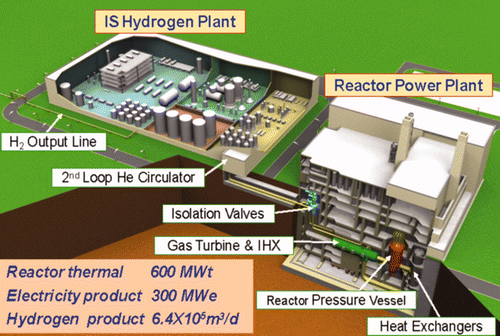
JAEA has developed a 30 MWt and 950°C high temperature test reactor (HTTR), whose operation began in 1998 and continues successfully to date Citation[14–Citation16]. With the experience, nuclear structural materials including IG-110 core graphite and Hastalloy-XR heat-resistant steel and significant know-how including design codes and licensing methods are qualified to design commercial reactors. By developing the balance of plant technologies, JAEA has completed a 10-year design study of commercial series GTHTR300C (Gas Turbine High Temperature Reactor of 300 MWe for Cogeneration), whose plant overview is depicted in . Since the design has been reported elsewhere Citation[17,Citation18], only the latest results on the plant operational design are described in detail.
Referring to , GTHTR300C consists of a 600 MWt HTGR with outlet coolant temperature of 950°C, an intermediate heat exchanger (IHX) to supply 900°C process heat to thermal production plant for hydrogen or other industrial product, a direct-cycle recuperated gas turbine to generate power while circulating reactor coolant. A precooler discharges the waste heat of the power conversion cycle. Although not shown, the waste heat of 160°C removed in the precooler can supply desalination and district heating without penalty to gas turbine power generation. A closed intermediate loop circulates hot helium from IHX to the distant thermal production plant. The same loop completes necessary environmental and material separation between the nuclear plant and the non-nuclear thermal production plant.
Figure 2. The GTHTR300C plant process control designed for cogeneration load follow of electricity and high-temperature heat or further hydrogen.
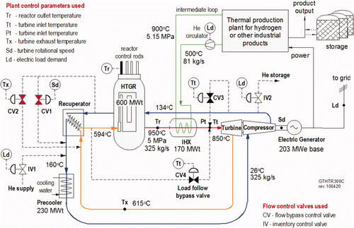
The gas turbine is a single-shaft, axial-flow design having 6 turbine stages and 20 compressor stages. The gas turbine is rated at 850°C turbine inlet, 280 MWe, and 3600 rpm. It drives a synchronous generator from shaft cold end. Although not discussed in this article, up to 300 MWe could be generated at a 950°C turbine inlet Citation[18]. While the design mostly complies with established practice in heavy-duty combustion gas turbine, the new equipment challenges as a result of working directly in the reactor coolant gas include helium compressor and magnetic bearing. JAEA has designed both equipment and validated their performance in 1/3-scale test Citation[19,Citation20]. The helium compressor exceeded the performance requirement. The magnetic bearing demonstrated the controllability above the first rotor dynamic bending mode, satisfying the requirement for suspension of gas turbine generator under 250 MWe. Further development for bearing is necessary for larger power rating.
The hydrogen production is based on thermochemical iodine–sulfur (IS) or steam electrolysis process. The IS process employs three inter-cyclic thermochemical reactions to decompose water molecules into hydrogen and oxygen gases. The process consumes water as the only material feedstock and all other process materials used are chemical reagents. The heat and electricity consumed by the process are supplied in-house by the reactor plant. The heat supports endothermic reactions and the electricity powers electrolyzers, gas circulators, pumps and other utilities of the process. JAEA validated the chemistries and closed-loop operation of the process and is currently engineering the process. Demonstration of nuclear production on the HTTR is planned after 2015.
The overall load-follow system of the GTHTR300C integrates four control strategies below:
| 1. | Control of turbine speed, Sd, through flow valve CV1. | ||||
| 2. | Control of recuperator low-pressure-side inlet temperature, Tx, through flow valve CV2. | ||||
| 3. | Control of turbine inlet temperature, Tt, by flow valve CV3. | ||||
| 4. | Control of turbine inlet temperature and pressure, Tt and Pt, by valves CV4, IV1 and IV2. | ||||
The first two strategies are known effective to control rapid transients such as loss of generator load in the HTGR direct-cycle gas turbine power generation systems [Citation8,Citation11,Citation21,Citation22]. They are expected to be also effective to control similar events in the present cogeneration system despite the additional topping IHX.
This study proposes the third strategy to automate heat rate to follow changes of up to an instantaneous loss of 100% heat load in the IHX. The IHX primary exit flow temperature would respond to the change in the secondary IHX heat load. To maintain the downstream turbine inlet temperature constant as the chief control objective, the flow valve CV3 opens or closes to introduce more or less of cold flow to upstream of the turbine from the compressor discharge to the turbine inlet. The overall control strategy aims to continue normal power generation, unaffected by a planned or forced heat load change, at near-steady power generating conditions including gas turbine aerodynamics and power conversion efficiency.
The current study further proposes the fourth control strategy to automate cogeneration load follow. The conditions to be met include (1) constant reactor temperature to avoid thermal stress in high temperature structure; (2) constant reactor thermal power to yield base load economics; and (3) constant power generation efficiency over the range of load follow. To keeping generating efficiency constant requires constant gas turbine aerodynamic parameters such as gas velocity, temperature, and pressure ratio. Three conditions are found to be achievable by regulating turbine shaft power regulation through monitoring and controlling turbine inlet temperature to be constant with “load-follow” flow bypass valve CV4 and by regulating turbine inlet Pt with inventory control valves IV1 and IV2, which connects the primary flow circuit to helium storage and supply tanks. The size of the valve CV4 dictates the extent of cogeneration load follow whereas the size of the inventory valves IV1 and IV2 limits the rate of load follow. At all times of cogeneration load follow, the core is kept in full power and temperature at nearly constant coolant flow, which minimizes reactivity transient. The reactor reactivity control rods are, in principle, not required to move by this control strategy.
4. Load-follow performance evaluation
A simulation model to evaluate performance of the plant design is built up with the distributed component models and material database of the GTHTR300C. The reactor is represented by point neutron kinetics of fission with various sources of reactivity feedback, heat generation and exchange in fuel blocks with hot and average coolant channels and in core reflector blocks with coolant channels. Other models include core upper and lower gas plena, control rod flow channels, core support cooling flow path, RPV, and vessel cooling systems. The recuperator model includes the high pressure fluid, the low pressure fluid, and metal plate surface. The precooler model includes the helium side, cooling water side, and helical-coiled tubing. The IHX model contains the primary coolant side, the intermediate loop helium side, and the tube bundle heat exchanging surface. The secondary helium flow is controllable by varying the helium circulator speed with variable speed motor to regulate the heat rate of the IHX. Heat transfer correlations are incorporated corresponding to the types of heat exchangers used in the plant. The vital performance models and material properties for the reactor, heat exchangers, and helium gas turbine have been validated by the HTTR operations and additional component model mock-up tests by JAEA. Simulation of overall plant system model is executed with the solver of RELAP5 MOD3. Information on RELAP can be found elsewhere Citation[23] and is not repeated here. Simulation results for a number of load duties are discussed in the following.
4.1. Base heat and power cogeneration
gives the GTHTR300C base heat and power cogeneration rates, which may be reset according to site-specific load requirement as described in Section 2. In the base cogeneration, the reactor outlet coolant of 950°C enters the primary side of the IHX and heats the secondary helium to 900°C. About 170 MWt of heat is exchanged in the IHX and carried by the intermediate loop to the hydrogen plant with production rate of 0.64 million Nm3 (58 tonnes) hydrogen per day Citation[17]. The balance of the reactor thermal power is converted to electric power in the reactor gas turbine plant. About 12% of the electricity rate is consumed in-house in the reactor and hydrogen plants and the balance is sent out to external grid.
Table 1. Base heat and power cogeneration parameters.
The plant startup begins with 10% coolant inventory to minimize power used to rotate the gas turbine. The reactor outlet is first raised to 850°C by gradually withdrawing the reactivity control rods. The coolant inventory is added to 100% to arrive at the primary circuit pressure of 5 MPa, at which time the base electric generation rate is attained. Thereafter, the reactor outlet temperature is raised by further withdrawing the control rods while the hydrogen plant is started and heated by rotating the secondary gas circulator. The base cogeneration rates are attained when the reactor outlet reaches 950°C. Reversing the steps taken in the two-tier startup procedure would execute a normal plant stoppage.
4.2. Loss of heat load
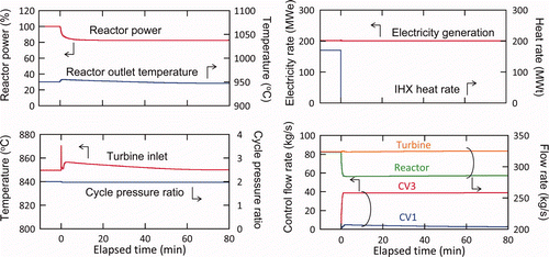
This represents the severest operational transient of heat load, in which the heat rate of the IHX is dropped to zero with complete stopping of the intermediate loop gas circulation and taking the hydrogen plant off-line. Detecting an immediate temperature rise of the IHX primary exit, the bypass valve CV3 opens to direct a cold helium flow stream to the turbine inlet, which prevents the turbine inlet gas temperature from rising more than 20°C, as indicated by the results in . Because of the CV3 coolant bypass from the core, the reactor power is reduced to 505 MWt by the sum of reactivity feedback of the fuel and moderator to their temperature changes and by modest control rod insertion in the core. This together with the large thermal capacity of the core is shown to keep the reactor outlet coolant temperature basically unchanged at 950°C. The fuel operating temperature is found to decrease by about 60°C from the initial base cogenerating condition. The CV1 is shown to control the turbine speed with minimal modulation in , which confirms sound stability of continuing power generation by the gas turbine.
In terms of equipment integrity, the IHX's Hastelloy-XR tubing is most challenged by the rapid transient. The tube metal temperature rises by 25°C from the base operation condition of 925°C, but the change in pressure load is insignificant. The largest impact is thermal stress resulting from a sudden drop of heat flux through the tube wall. The preliminarily estimated creep damage of pertinent mechanisms to the IHX tubing per event is given in . Accordingly, the accepted repetitions of the event would be around 50 in the 20-year service life of the IHX so that the accumulated creep damage would be limited to less than 0.5, which is a half of the design criteria of 1.0. Based on the HTTR IHX design knowledge Citation[24], a detailed inelastic analysis is expected to show that actual creep-fatigue damage from the recurrence of the thermal stress would accumulate much slower due to mechanism of stress relaxation in the Hastelloy-XR high temperature tubing.
Table 2. Estimated creep damage to IHX per event of loss of heat.
The 400-mm diameter (i.e. 400A) CV3 valve and its controller proportional gain are rated to limit overheating of turbine hot flow path to as low as 20°C, with which the turbine blades and vanes made of Ni-base directional solidified alloy remain under the material's stress limits. Furthermore, integral control for the CV3 is tuned to return the turbine inlet gas to the rated temperature quickly, as shown in , to prevent accelerated creep damage to blade.
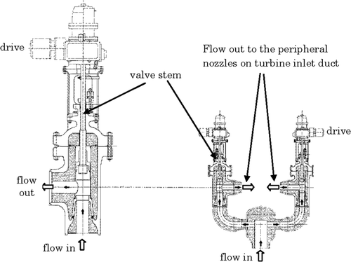
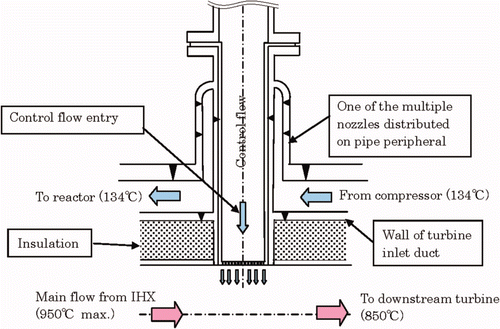
A flow mixer consisting of multiple units of the nozzle shown in , which are arranged on the perimeter of the turbine inlet duct, is designed to promote mixing of control flow with main flow prior to the turbine in order to avoid hot streak in turbine hot flow path. All pressure bearing walls of the mixer are exposed to compressor discharged temperature of 134°C. The insulation applied on inner wall of the turbine inlet duct isolates the hot gas flows from the cooled metal structure.
Figure 4. Mixer of control flow with main flow to develop uniform gas temperature prior to turbine inlet.
To anticipate extended outage of heat load, reactor outlet coolant temperature can be lowered to 850°C by moving control rods in the core to compensate for the change of the core temperature. This is accompanied by a closing of the CV3. The control operation is gradual without generating adverse effect on equipment life. Completing the control yields a standalone electricity generation at the base rate. The power generation may increase to 280 MWe by raising primary coolant inventory, in which the reactor power follows to return to 600 MWt due to the reactivity feedback of temperature from the change in the core coolant flow rate.
4.3. Loss of electricity load
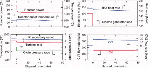
This represents the severest operational disturbance to the plant by the off-site grid. The plant intends to continue generation of heat and house-load electricity. When detecting acceleration of turbine speed following the loss of the generator load, the valve CV1 opens rapidly, whose fast action appears in as a spike given the relatively large time scale of the graph, to both bypass flow from the turbine and drop the turbine pressure ratio. As a result, the turbine sees a rapid power reduction to the house load. The CV1 and its controller are rated to limit turbine overspeed, less than 10% maximum, and return it to the rated speed quickly. In the mean time, reactor power reduces to 66% under the reactivity feedback of temperature due to the core coolant reduction and by modest control rod insertion in the core. The reactor outlet coolant remains around the rated 950°C. The reactor is shown to operate in a new steady state after a short period of transient.
As a result of flow bypass via CV1, the IHX primary flow rate is reduced, forcing a slightly less than 10% reduction in the IHX heat rate and causes the flow temperature at the IHX secondary outlet to drop by 18°C as shown in . The temperature drop would decrease the hydrogen conversion efficiency by 2%. The reductions of the heat rate and efficiency combine to cause an estimated 15% loss of hydrogen production rate. In practice, however, a long-term operation at faulty electric grid is not expected. The base cogeneration of power and heat is fully recoverable by closing the CV1.
Turbine gas path reduces by 40°C in the first stage but increases by 60°C in the exit stage. All blades and vanes of all turbine stages are confirmed to stay in the gas path materials' temperature-dependent stress limits. Compressor operation is stable as the transient moves it farther from its stall line. The compact plate-fin recuperator made of SS 316 is protected from the rise of turbine exhaust temperature by the 150A valve CV2 that opens quickly, whose reaction also appears as a spike in the figure, to limit temperature from rising more than 20°C and returns it to the base condition. The recuperator transient temperatures are omitted from the figure for clarity. Finite-element analysis confirms the resulting thermal stress in the recuperator heat transfer metal surfaces to be negligible.
The above attemperation in the recuperator simultaneously limits change in reactor inlet gas temperature. This together with thermal damping and the power reduction of the core limits change in the core outlet coolant temperature. The fuel temperatures initially rise by 10°C maximum and fall to steady values by about 100°C below the initial base operation conditions over time. No condition is identified that would prevent reactor from operation in partial power to continue the IHX heat supply.
The rise in the IHX tube temperature is 11°C maximum from the base condition. Furthermore, thermal stress is generated due to changing heat flux through the tubing wall. The third major concern is the pressure differential on the tubing that peaks to 0.94 MPa in the 10th second and settles to a steady value of 0.75MPa after about 3 min, which would add creep damage to the tubes if not relieved. lists the estimated creep damages per event to the tubes, of which the pressure load is assumed of 250 h duration. Accordingly, the IHX as designed can accommodate 60 repetitions of the event with the total creep damage not to exceed 0.5 during the 20 years of the IHX life. Note that the loss of off-site electric grid is typically considered of one event per year in nuclear plant design. Similar to the HTTR IHX operation, any large pressure load is relieved by adjusting pressure of the intermediate loop. In this case, the allowable number of the event repetitions increase to about 100.
Table 3. Estimated creep damage to IHX per event of loss of electric load.
4.4. Variable power and heat cogeneration
The ability to follow variable power and heat loads is simulated in of a plant response to an electric demand increase of 5% of the base rate per minute with corresponding reduction of the heat rate, which is the maximum requirement for cogeneration load follow. The reactor remains at 100% power at all times. Starting from the base cogeneration rates, turbine power generation is raised to follow the electric load demand increase by increasing the primary coolant inventory through the inventory control valve IV1. The IHX heat rate to the hydrogen plant is lowered by lowering the intermediate loop flow circulation rate with the variable speed gas circulator. As the primary exit temperature of the IHX begins to rise, the valve CV4 is opened, by active or pre-scheduled control to follow load demand, to direct cold flow from compressor discharge to mix with the hot exit gas of the IHX primary side. The goal of applying flow bypass via CV4 to maintain turbine inlet temperature near the rated 850°C is achieved as shown in . The power sent out to external grid increases to 276 MWe from 178 MWe in as little as 7 min. The pressure in the reactor and at turbine inlet increases to 7 from 5 MPa. To return to the base cogeneration rates, the control is reversed by reducing primary coolant inventory through another inventory control valve IV2 and simultaneously closing the bypass valve VC4.
Figure 6. Simulation of variable electricity and heat cogeneration to follow +5%/min grid electric load peaking.
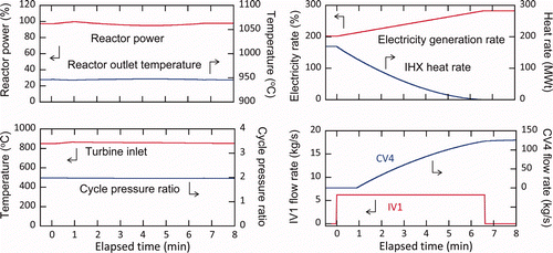
The key feature of the newly proposed scheme is that the reactor operates at full power with little changes in the core and fuel temperatures despite the rapid and wide-ranging load following. Under this condition, the control rod position is essentially unchanged. The core coolant temperatures are not changed, so is the core coolant flow. The rise in coolant pressure has no appreciable effect on the core and fuel temperatures. The heat transfer conditions in the core remain in the well-developed turbulent flow regime in the entire load range of interest. In sum, the overall reactivity and thermal conditions in the core are not disturbed during the entire period of load following. Another feature of the control scheme is that the operating points of the gas turbine including turbine inlet temperature and pressure ratio are unchanged as shown in such that aerodynamic performance of both turbine and compressor remains at their optimum design conditions. This allows a constant power generation efficiency of 46% during the load following.
The simulation confirms that the primary stress and the temperature transient in the various sections of the IHX tubing remain within the base operation conditions. It is important to note from the previous HTTR IHX experience that both inelastic strain (<1%) and creep fatigue accumulate in only the initial 2 to 3 thermal cycles of an IHX operation at high temperature, including startup and shutdown, but not later cycles due to the mechanism of stress relaxation Citation[24,Citation25]. In other words, merely repetition of a large number of load follow cycles such as daily load follow does not necessarily shorten the design service life of the IHX. In practice as is done in the HTTR, anticipated load cycles are evaluated in the life design of the IHX and actual operations are then monitored for any significant departure that might warrant re-evaluation.
Because the CV4 valve connecting the inlets of the reactor and turbine exposes to small pressure head, its flow coefficient tends to be large. This would require a sizable valve for a large plant tasked to perform an extended range of load following. A large valve can blunt speed and accuracy of valve modulation. The alternative designs shown in address this engineering challenge. The plural valves of the multi-valve unit are each connected to the similar count of the nozzles on the turbine inlet duct as shown in . The advantages of the multiple-valve design include control sequencing and redundancy as well as that the number of valve units can be added or subtracted to meet the flow capacity or the range of load following to be performed by a plant. A total of 6 units of 400A valve are used to yield the load follow results of the GTHTR300C in .
4.5. Standalone power generation
The HTTR reactor is designed to operate at dual outlet temperatures of 850°C and 950°C in full power, which is arrived by altering coolant flow rates while adjusting control rod position to compensate for the temperature coefficient of the core.
This proven operation principle is applied to the GTHTR300C. When a standalone power generation rather than cogeneration is desired, the IHX heat rate is fully unloaded and the turbine power generation can be increased at a rate of up to 5%/min by using control valves IV1 and CV4 until the full power generation capacity is reached as described in Section 4.4 and displayed in . The same results appear to be vertical lines at the beginning transient in only because of the greater time scale used there. To continue the standalone power generation over long term, reactor outlet coolant temperature is reduced to 850°C by inserting the control rods in the core. The rate of reactor outlet temperature reduction is purposely gradual at about 15°C/h, shown to closely follow the dotted curve of temperature control command in , in order to avoid thermally overstressing the reactor high temperature structure. The same is exercised in the HTTR operation. As the reactor outlet temperature decreases, valve CV4 closes until fully shut when the reactor outlet temperature arrives at 850°C equal to the turbine inlet temperature. The end of the control operation after 7.8 h yields a standalone electric power generation of 280 MWe at reactor full power and outlet coolant of 850°C and 7 MPa. Thereafter, the standalone power generation can continue indefinitely if desired, although for simplicity it runs for only half an hour in . The fuel temperature is 170°C lower than the base cogeneration condition, resulting more favorable operating conditions of the fuel. The IHX sees also a more benign thermal condition at 850°C maximum.
Figure 8. Simulation of transits from the base cogeneration to standalone power generation and then back with the reactor remaining in full power.
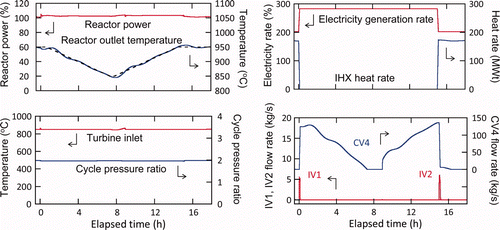
To recover to the base cogeneration from the standalone power generation, the control procedure is reversely executed, starting at about 8.4 h in , with the exception for the IV1, which remains closed. Instead, the valve IV2 is opened to reduce the coolant inventory in the primary system circuit.
5. Summary and conclusion
This work evaluates the technical feasibility of HTGR for demanding cogeneration load follow. The evaluation produces the GTHTR300C plant design employing a 600 MWt HTGR, a direct cycle gas turbine for power generation, and a topping IHX for cogeneration of high temperature process heat. The control methods incorporated in the design are shown able to automate operation transients for a wide range of load-follow duties including variable cogeneration, standalone power or heat generation, and rapid electricity peaking. These duties are performed without thermally overstressing the critical reactor structure and equipment. With the exception of controlling a loss of load, the load follow proceeds at full reactor thermal power output to maximize nuclear plant economics. The simulation results presented in the article exhibit the following specific performance limits below:
| 1. | Cogenerate the base rates of 200 MWe electricity and 170 MWt process heat of 900°C. | ||||
| 2. | Maintain the base rate of electricity generation in case of a loss of 100% heat load. | ||||
| 3. | Maintain at least 90% base rate of heat generation in case of a loss of 100% grid electric load. | ||||
| 4. | Peak electricity generation at ±5%/min in the 200–280 MWe range. | ||||
| 5. | Long-term standalone generation of 280 MWe electricity at 850°C core outlet. | ||||
These results confirm a strong potential for the HTGR to perform demanding duties of cogeneration load follow in the production and supply of power and high temperature heat to process industries and remote applications.
References
- A Technology Roadmap for Generation IV Nuclear Energy Systems . 2002 . The US DOE Nuclear Energy Research Advisory Committee and the Generation IV International Forum December
- GIF R&D Outlook for Generation IV Nuclear Energy Systems . Generation-IV International Forum 21 August 2009. Available at http://www.gen-4.org/PDFs/GIF_RD_Outlook_for_Generation_IV_Nuclear_Energy_Systems.pdf
- J. Gauthier, B. Ballot, J. Lebrun, M. Lecomte, D. Hittner, and F. , Carre . 2007 . Potential application for nuclear energy besides electricity generation: A global perspective . J. Nuclear Eng. Technol , 39
- Bogusch , E and D. Hittner, C. Viala, C. Angulo, V. Chauvet, M. Fütterer, S. Groot, W. Lensa, K. Verfondern, O. Baudrand, J. Ruer, G. Griffay, and A. Baaten . EUROPAIRS: The Major Nuclear Cogeneration Project in FP7, HTR-2010-44 . Proceedings of HTR2010 . Czech Republic, 18–20 October 2010
- US Department of Energy's Office of Nuclear Energy . Next generation nuclear plant demonstration project February 2010. Available at http://www.nextgenerationnuclearplant.com
- Tatematsu , K and H. Kawasaki, M. Nemoto, and M. Murakami . Long-term outlet of energy demand and supply in Japan – estimation of energy demand and supply for “Nuclear Energy Vision 2100” of JAEA , JAEA-Research 2009-007, Japan Atomic Energy Agency . June 2009
- Sakaba , N and Y. Tachibana, S. Shimakawa, H. Ohashi, H. Sato, X. Yan, T. Murakami, K. Ohashi, S. Nakagawa, M. Goto, S. Ueta, Y. Mozumi, Y. Imai, N. Tanaka, H. Okuda, J. Iwatsuki, S. Kubo, S. Takada, T. Nishihara, and K. Kunitomi . Examination on small-sized cogeneration HTGR for developing countries , JAEA-Technology 2008-019, Japan Atomic Energy Agency . March 2008
- Rodriguez , C , Zgliczynski , J and Pfremmer , D . GT-MHR operations and control . Proceedings of the International Atomic Energy Agency (IAEA) Technical Committee Meeting on Development Status of Modular High Temperature Reactors and Their Future Role . pp. 28 – 30 . November
- Wunderlich , F and Schlemmer , F . 1984 . LWR load following operation: fuel rod design and experimental basis . ANS Trans , 47 : 199
- Fischer , G and F. Sontheimer, I. Ruyter, and J. Markgraf . 1988 . Experiments on the load following behaviour of PWR fuel rods . J. Nuclear Eng. Design , 108 : 429 – 432 .
- Yan , X and Lidsky , L . Highly efficient automated control for an MGR gas turbine power plant, ASME 91-GT-296 . International Gas Turbine and Aeroengine Congress and Exposition . pp. 3 – 6 . June 1991
- Gittus , J and Howl , D . 1979 . Predicting load follow damage . J. Nuclear Mater , 87 : 268 – 273 .
- Pouret , L , Buttery , N and Nuttall , W . 2009 . Is nuclear power inflexible? . Nuclear Future , 5 : 333 – 344 .
- K. Takamatsu, K. Sawa, K. Kunitomi, R. Hino, M. Ogawa, Y. Komori, T. Nakazawa, T. Iyoku, N. Fujimoto, T. Nishihara, and M. Shinozaki, High-Temperature Continuous Operation of the HTTR, AESJ Trans 10(4) (2011), pp. 290–300
- Fujikawa , S and H. Hayashi, T. Nakazawa, K. Kawasaki, T. Iyoku, S. Nakagawa, and N. Sakaba . 2004 . Achievement of reactor-outlet coolant temperature of 950°C in HTTR . J. Nucl. Sci. Technol , 41 : 1245 – 1254 .
- Saito , S and T. Tanaka, Y. Sudo, O. Baba, M. Shindo, et al . 1994 . Design of high temperature engineering test reactor , Japan Atomic Energy Agency, JAERI 1332 .
- Kunitomi , K and X. Yan, T. Nishihara, N. Sakaba, and T. Mouri . 2007 . JAEA's VHTR for hydrogen and electricity cogeneration: GTHTR300C . Nucl. Eng. Technol , 39 : 9 – 20 .
- Yan , X and K. Kunitomi, T. Nakata, and S. Shiozawa . 2003 . Design and development of the GTHT R300 . Nucl. Eng. Des , 222 : 247 – 262 .
- Takizuka , T and S. Takada, X. Yan, S. Kosugiyama, S. Katanishi, and K. Kunitomi . 2004 . R&D on the power conversion system for gas turbine high temperature reactors . Nucl. Eng. Des , 233 : 329 – 346 .
- Yan , X and T. Takizuka, K. Kunitomi, H. Itaka, and K. Takahashi . 2008 . Aerodynamic design, model test and CFD analysis for multistage axial helium compressor . J. Turbomachinery 130/031018 , : 1 – 12 .
- Kadak , A . 2007 . MIT pebble bed reactor project . J. Nucl. Eng. Technol , 39 : 95 – 102 .
- Kiryushin , A and N. Kodochigov, N. Kouzavkov, N. Ponomarev-Stepnoi, E. Gloushkov, and V. Grebennik . 1997 . Project of the GT-MHR high-temperature helium reactor with gas turbine, Nucl. Eng. Des 119 – 129 .
- RELAP/MOD Volume I: Code Structure . System Models, and Solution Methods Nureg/Cr-5535, June 1995
- Koikegami , H and S. Maruyama, K. Kunitomi, and M. Ohkubo . Design and fabrication of He-He intermediate heat exchanger for HTTR, Japan Atomic Energy Research Institute . JAERI-conference 96-010 . pp. 307 – 321 . July 1996, pp.
- Hada , K and I. Nishiguchi, Y. Muto, and H. Tsuji . 1991 . Developments of metallic materials and a high-temperature structural design code for the HTTR . J. Nucl. Eng. Des , 132 : 1 – 11 .
