
Abstract
This paper assesses the comparative practices between Europe and North America with respect to the design of bored pile/drilled shaft foundations. Several major trends are identified that are common to both regions: (1) increasing complexity in the project demands and applications, and (2) more stringent testing and quality assurance requirements. The design codes differ in some respects but the most striking similarity between the European Union (EU) and the United States is the tendency for local (or national in the case of the EU) variations to persist in the implementation of design practices. Some of the variations reflect geologic differences, but much of the inconsistencies in design practice appear to be artefacts of the evolution of local practice that are not easily relinquished. Other common issues identified in the study include the wide local variations in constructability concerns with respect to concrete mix characteristics, reinforcement details and the influence of construction techniques on foundation performance.
Introduction
The design of deep foundations in Europe and North America exhibits diverse standards and codes. The national, state, regional and even municipal code requirements result in considerable differences in design approaches. As a result, design practices are unsurprisingly inconsistent between the two continents. For example, a review of practice in the U.S. for the design of drilled shafts for axial loading reveals that the computation of static resistance is region specific, and the design is often based on historic precedent or prescriptive local codes. Practice in some areas of the U.S. use only end bearing in rock (or similar bearing stratum) neglecting side resistance, while others use only side resistance while completely neglecting end bearing. Load testing was found to be relatively more common on large public works projects and relatively uncommon on commercial work. In contrast, review of the practice in the European Union (EU) for the design of bored piles for axial loading reveal that computation of static resistance is country specific, although based on the same code formulation (i.e. EC7). Design is often based on precedent or prescriptive local codes. Practice, in some cases, uses only end bearing in rock (or similar bearing stratum). The importance of load testing was found to be largely variable according to local practice; while load testing is very common in U.K., it is nearly inexistent in the Netherlands.
The selection of pile types and deep foundation systems is driven by many external and internal factors. Common trends were observed for both the U.S. and the E.U., and are expected to be similar for other countries worldwide. Among those, the following general criteria contributing to the selection of bored piles/drilled shafts were identified. First, an increased tendency for the construction of tall buildings and infrastructure (e.g. high-rise commercial and residential towers, heavy structures (industrial), and bridge and other infrastructure systems) is leading to maximised loads. This trend influences the search of bearing strata at suitable depths, which is expected to be increasingly difficult in the near future. This is illustrated by the new records for pile length established by the Lakhta Tower in the Centre of St. Petersburg (82 m in length by 2.0 m in diameter; Huemmeler et al. Citation2014) and at the cable-stayed bridge in Tunis (100 m in length by 2.0 m in diameter; Zaghouani, Chouikha and Haffoudhi Citation2013). Second, selection of locations is governed by commercial or strategic factors with the consequence of difficult building environment and more critical soil conditions. Third, deep foundation construction is increasingly influenced by environmental- and urban-related considerations. Fourth, development of advanced computer models to create particularly challenging architectural concepts has led, in turn, to increasingly complex structural design requirements. Fifth, more sophisticated construction procedures result in the suppression of footings (e.g. top-down, cofferdam, congested areas, etc.). Sixth, complex loading conditions, such as combined loading under axial and lateral forces, pose design criteria that require the consideration of high lateral demands or the evaluation of liquefaction and lateral spreading. In the ensuing sections, differences in selecting, designing, constructing and verifying bored piles (European denomination)/drilled shafts (North American denomination) are explained and evaluated.
Design guidelines and code standards
Recommendations in the United States
The design of drilled shafts in the U.S. is affected by a variety of codes, primarily related to the type of project. These codes often differ significantly in their requirements, as outlined briefly below.
Highway bridges
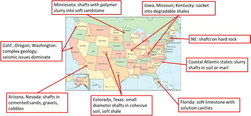
Transportation structures involving roadways are generally designed according to the AASHTO code (American Association of State Highway and Transportation Officials Citation2016), and the design guidelines produced by the Federal Highway Administration are freely distributed and widely referenced across the industry. Load and resistance factor design (LRFD) is generally used for design, with a range of resistance factors depending on conditions, load testing and other factors (e.g. extreme event conditions). State departments of transportation (DOT’S) often have their own local guidelines and design practices, which may include deviations from the basic AASHTO code. For example, Florida DOT has design guidelines for soft limestone that employs a methodology for computation of axial side resistance that is developed uniquely for the geologic conditions in Florida. Not surprisingly, the diverse geologic conditions across the North American continent result in a diversity of design approaches for drilled shaft foundations, of which a few examples are illustrated in .
1 Examples of diverse geologic conditions for drilled shaft design
Rail bridges
Other transportation structures including heavy rail and light rail or transit system structures often reference the AREMA code, which uses an allowable stress design (ASD) approach with a prescribed factor of safety against service loads. The AREMA code is silent regarding methods for estimating axial resistance, leaving considerable discretion to the geotechnical designer, as compared with AASHTO.
Commercial and industrial buildings
The most widely referenced code for building structures across the U.S. is the international building code (International Code Council Citation2011). This code uses an ASD approach with specified factors of safety for design against bearing failure. Perhaps the most relevant provisions of the IBC affecting foundation engineering are the provisions that define the site class for seismic design, which may influence the need to design drilled shafts for flexural strength below grade. The design engineer is responsible for determining acceptable means for computing axial resistance of drilled shafts. The state of California provides a building code (CBC), which includes seismic provisions affecting drilled shaft design, but also references IBC for more general aspects. Local building codes often reference IBC, but many include more specific and often prescriptive requirements related to design and testing of drilled shafts. Some large U.S. cities implement such codes (e.g. New York and Chicago), but drilled shaft design from the standpoint of the determination of geotechnical resistance is largely subject to the discretion of the responsible geotechnical engineer across most of the U.S.
Structural design
The structural design of drilled shafts in the U.S. is largely controlled by the provisions of the American Concrete Institute (ACI) via ‘Building Code Requirements for Structural Concrete (ACI Committee 318 Citation2014)’, which is referenced by AASHTO, IBC, CBC, AREMA and most local building codes. ACI 318 is focused on an LRFD approach to structural design, although ASD is allowed. ACI 318 includes provisions specific to cast-in-place deep foundations (referred to as ‘Drilled piers’ or ‘Caissons’); however, some of the provisions within the chapter on foundations refer back to the section on columns, and the applicability of some requirements for drilled shafts can be unclear. Many state DOT agencies have structure design guidelines and some may include provisions for drilled shafts. For example, Caltrans has some specific structure design guidance for drilled shafts (called ‘Cast-in-Drilled-Hole’ piles, CIDH piles) relative to seismic loading and the connection to the column. In many cases, the drilled shaft is designed to be ‘capacity protected’ for seismic loading; i.e. the flexural strength must exceed that of the column so that an overstress condition produces a hinge at the base of the column and the foundation remains undamaged.
Electrical power
This industry represents a significant use of drilled shafts, and the major application of drilled shafts for support of transmission structures is typically controlled by stability for lateral and overturning forces. Many, but not all, utility companies participate in the Electrical Power Research Institute (EPRI), which provides design guidance for drilled shaft foundations. However, EPRI is not a code-producing organisation, and the utilities, which own the transmission structures, set their own policy individually with respect to design and performance criteria. Electrical power generating facilities are generally handled in a manner similar to other industrial facilities, with only the broadest governance by building codes. Nuclear power plants are subject to much greater scrutiny, but there has been relatively little new construction activity in the nuclear industry in the U.S. in recent decades.
Other governmental agencies
Public works, such as governmental buildings, typically follow local building codes. The U.S. Army Corps of Engineers is a large agency responsible for water projects, some military installations, and other structures, and have their own specific design guidelines.
Design standards and codes in the EU
A large variety of code recommendations apply in the EU for the design of bored piles. Differences exist from country-to-country but also according to project type. Although specific private clients may consider different rules, European Standards commonly apply since 1997, and have received the force of norm in most countries. The following can be distinguished:
The Eurocodes
Numbered from EC0 to EC9, the Eurocodes cover a wide range of design for construction of bored piles. The following are the most relevant codes for the deep foundation industry: Eurocode 2 – which provides recommendations for the design of concrete structures; and the following for the geotechnical design of deep foundations: Eurocode 7 – Parts 1 and 2 (CEN/TC 250/SC7; British Standards Institution Citation1995), EN 1997-1 Geotechnical design – Part 1: General rules (CEN Citation2004); EN 1997-2 Geotechnical design – Part 2: Ground investigation and testing (CEN Citation2007) as well as Eurocode 8 – Part 5 for seismic design (CEN/TC 250/SC 8).
Execution codes
Beside the Eurocodes, execution codes were drafted at the initiative of the contractors: Execution of Special Geotechnical Works (CEN/TC 288) and Geotechnical Investigation and Testing (CEN/TC 341).
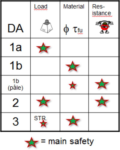
In most countries in Europe, the design of deep foundations is thus based on Eurocode 7 (EC7). EC 7 is a general framework, which defines a common terminology and the general principles to be followed. The development of the unified Eurocode consisted of combining several existing national design methodologies, which resulted in a complex choice between three design approaches. The three design approaches define how the partial factors are applied on the loads or actions (γF), the materials and the ground (γM), and the resistances (γR). For example, in Design Approach 2, the partial factors are applied on the loads or the actions (equal to the effects of the loads) and on the resistance.
EC 7 has to be accompanied by the respective National Annexes, which describe the ‘real’ national calculation method (i.e. defining the way the end bearing and shaft friction is computed, as described below), and specify which design approach, i.e. DA 1/1, 2 or 3 (), should be pursued. National annexes have been recently or are currently being introduced in most countries, and mostly reflect older practices in the different countries. However, the introduction of EC 7 was the opportunity to re-develop some of the old and obsolete approaches, and to re-draft the national codes in the spirit of recent developments, research and construction practices.
2 Design approaches outlined in Eurocode 7
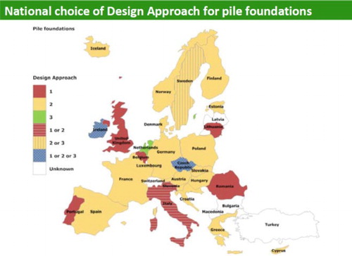
The general principle behind EC7 is the design of deep foundations using ultimate limit states, which ought to be verified for both: geotechnical and structural design Ed ≤ Rd. The following are some key approaches to geotechnical design outlined in EC 7: (1) the failure criterion is defined as settlement corresponding to a pile-head settlement of 10% of the pile diameter under axial loading; (2) partial safety factors are applied on loads or their effects and/or to the soil parameters and/or to the resistances (which corresponds to a sort of LRFD); (3) the weight of these safety factors will depend on the design approach in the respective country (); (4) the introduction of correlation factors for deriving the characteristic compressive and tensile resistances of piles shall be taken from static pile load tests or ground test results; and (5) the serviceability limit state should be checked with respect to pile settlement and displacement. An overview of the design approaches selected by different European countries, and the weight of the safety factors provided in .
3 Diversity of European practice with bored pile design
Definition of the characteristic value in EC 7
The characteristic value is calculated using the ultimate bearing capacity, a model factor and correlations factors. The model factor evaluates the safety and the reality of the calculations. The correlations factors define the knowledge or uncertainties pertaining to the pile’s behaviour and/or the ground variability. The characteristic value is a theoretical value without partial safety factors. The design value is derived from this characteristic value by applying partial safety factors. For example, the characteristic end bearing and shaft friction can be computed using existing and recognised methods either by:
Direct methods – a unit base and shaft resistance is directly derived from the soil investigation: France, Netherlands and Belgium;
Indirect methods – soil parameters are derived from soil investigations, which are then used for the assessment of the pile capacity: UK, Germany and Italy. Design is sometimes also based on historical values using existing databases (e.g. Germany – EA pfähle);
Static load testing; and
Dynamic load testing and high-strain dynamic testing
Load tests
EC 7 recognises the importance of static load tests (directly or indirectly) as the basis of pile design methods (clause 7.4.1(1)P), and emphasises the conduction of load testing through the code document: “The design shall be based on […]: … ‘the results of static load tests’, … ‘empirical or analytical calculation methods whose validity has been demonstrated by static load tests’ or ‘the results of dynamic load tests whose validity has been demonstrated by static load tests’”. However, depending on the country, the importance of load testing varies. It can be used to establish and demonstrate the factors used in the computation of the ultimate resistance with direct methods (research load testing), or to validate design based on experience values, or indirect methods (site load testing). In some cases, load tests are used as a quality control tool.
Geotechnical information used for design
With regard to site investigation, common issues relate to the large variation in quality of available information, major geographical variations in the approaches used (some of these logically linked with geological conditions but not always), the coverage of borings in commercial practice (which is typically much less thorough than in public projects) and the availability of reliable information with respect to groundwater levels.
Site investigation: U.S. practice
The majority of site investigations for drilled shaft design in the U.S. is comprised of conventional exploratory borings with in-situ tests conducted with the standard penetration test (SPT) method, possibly accompanied by coring of rock. Cone penetration testing (CPT) is widely accepted in U.S. practice, but is not common for drilled shaft design because of the nature of the conditions for which drilled shafts are most often used (i.e. the CPT cannot routinely penetrate the strong bearing layers, which tend to favour the use of drilled shafts). In some areas where dense gravelly soils are present (e.g. California, Arizona and Nevada), casing drill systems may be employed with penetration measurements provided by a Becker Hammer drilling system. Texas DOT routinely uses a downhole dynamic cone penetration test. All of these penetration test methods are generally recognised as crude measurements of soil strength, but the techniques reflect the difficulty in routine sampling and testing.
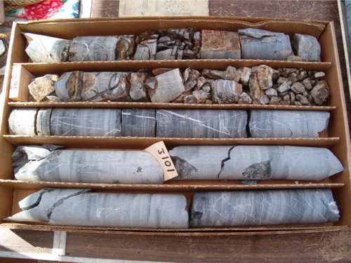
A significant portion of the utilisation of drilled shafts in the U.S. involves foundations seated on or socketed into rock or rock-like materials. Coring is commonly employed for site exploration in these circumstances. The most widely used parameters include the percentage recovery and the rock-quality designation (RQD) determined from the recovered cores (), with the rock material itself characterised by geological descriptions and a description of the joints and other discontinuities. Rock classification includes the rock mass rating (Bieniawski Citation1989) and the Geologic Strength Index (Marinos and Hoek Citation2000), which is becoming relatively well recognised. Some local codes or agencies have their own specific classification systems (e.g. Caltrans or New York City Building Code). Unconfined compression tests may be performed on selected samples of intact rock, with point load index test measurements where large cores are not available. It is noted that contractors often desire this information for their own bidding and planning purposes, even if the geotechnical designer is not so interested in the uniaxial strength of the hardest layers. Other tools that are occasionally employed include downhole acoustic televiewer (ATV) and seismic shear wave velocity measurements (crosshole or sometimes downhole).
4 Rock core samples for drilled shaft design
Groundwater information is particularly important to the contractor and relevant to design of foundations, but in routine practice this information is often neglected or poorly documented. The IBC only specifically requires groundwater information where groundwater is anticipated to be within 5 ft (1.5 m) of the lowest floor level. Where drilled shafts are installed to bear on or into rock, many designers may take little account of groundwater because it has no effect upon prescriptive bearing values used for computation of axial resistance in rock.
For most commercial building projects, the scope of the site investigation, including the frequency and the required depth of borings, is left to the discretion of the ‘registered design professional’ (IBC), and economic or schedule pressures can lead to relatively low coverage of borings across the building site. The AASHTO code requires a minimum of one boring per pier where the width is 100 ft (30 m) or less, and at least two borings at piers over 100 ft (30 m) wide. Additionally, for drilled shafts, the criteria listed in will apply.
Table 1 Boring requirements for drilled shafts in AASHTO code
Boring depths are required to penetrate to a depth of 20 ft (6 m) below the anticipated drilled shaft tip elevation when bearing in soil, and 10 ft (3 m) below the anticipated tip elevation in rock. In reality, boring coverage is often less and state DOT agencies are free to set their own standards that can sometimes conflict with AASHTO. In some specific types of geology such as limestone with the potential for solution cavities or other highly variable rock formations, some agencies may require a boring at every drilled shaft location. Occasionally, these are implemented post-design during construction as confirmatory borings. Where design-build (DB) work is performed for transportation projects, the AASHTO code provisions are often cited as a contractual requirement. It is noted that inspection of conditions encountered during construction may be used in some circumstances as a substitute for a more extensive investigation if the design includes flexibility with respect to the final drilled shaft tip elevations. As long as the responsible designer (or representative) can observe the excavated materials during construction and make engineering decisions in the field in a timely manner without undue delay of construction, this process can work very well at ensuring that a robust and reliable design is implemented even without an extensive pre-construction site investigation.
Site investigation: EU practice
Site investigation methods vary largely by region, both in quality and in quantity. The type of investigation method is influenced by several factors, such as the design method and the local geology, but also historical practice, local prescriptions and professional habits, and, in many cases, associated costs. Direct methods will usually employ CPT testing as well as Pressuremeter testing. CPT is widely used in soft soils (e.g. tertiary clay, sand and weathered material), hence, its application is extensive in the low lands and delta areas, such as Belgium, Netherlands, France, Italy, Germany, UK and Nordic countries. The Pressuremeter is historically used in France, but gained significant popularity for the design of bored piles in rock in Italy and Belgium, as it provides resistance values even in rock or rock-like material.
Indirect methods use coring of rock and rock-like material. As in the U.S., the rock material will be characterised by geological descriptions and a description of the joints and other discontinuities, and the most widely used parameters include % recovery and RQD determined from the recovered cores. Cores are often used for laboratory testing, such as unconfined compression tests. Codes often refer to strength categories, which, in some cases, are referred to for the application of different drilling rates in the bill of quantities. Given the tradition and cost of SPT testing, soil characterisation via SPT is largely applied in most European countries. Together with the geological description, SPT provides an indication of strength, which is related to resistance values in the codes. The quality of SPT tests is very variable, which will determine the relevance of the measured resistances.
The quality and the quantity of the soil investigation will largely depend on local uses and type of project. Large projects will typically follow strict guidelines based on EC7 recommendations (see below). For large public works, a good quality baseline report is usually available, although exceptions occur. Pre-bid soil investigation for commercial practice and smaller sizes project vary by country, and depend on national regulation systems and the type of clients. EC7 identifies three geotechnical categories on the basis of the degree of complexity of the superstructure design, the ground conditions and the interaction between the aforementioned and the environment. Category 1 describes small simple structures on uncomplicated, clearly defined ground conditions and assumes that stability can be assessed on the basis of experience. Geotechnical Category 2 is assigned to structures and ground conditions with more complexity that involves the execution of a stability analysis and requires the participation of a qualified geotechnical specialist. Category 3 is reserved for highly complex structures and/or ground conditions, where safety must be verified numerically. Category 3 requires the involvement of a qualified geotechnical specialist with extensive knowledge and experience.
EC 7 furthermore includes guidelines with respect to frequency/spacing (s) and depth depending on the importance of the construction. The following recommendations apply with respect to spacing: s = 15–40 m for high-rise and industrial structures, 60 m for large-area structures and 20–200 m for linear structures. The required depth of investigation are the largest value of 5 m under the pile base, 3 × enlarged base, or 1 × smallest side of a pile group.
Moreover, EC7 introduces a reduction factor, Rc;k, [equation (1)] based on the relative importance of the soil investigation, expressed through the correlation factors ξ (). The values of the correlation factors can decrease the overall safety on the bearing capacity. This factor quantifies the better knowledge of the soil around the piles.(1)
Table 2 Ground test results (n = number of profiles)
Subsurface risk
Subsurface risk assessment in the U.S.
The issues pertaining to subsurface risks are closely related to the site investigation performed during design, which provides the basis for the contractors bid. The description of ground conditions may have a profound impact on the means and methods that are planned and priced during the bidding phase of the work. Although this aspect of the site investigation is quite important, it is not specifically addressed by building codes, and there exists wide variations in the level of consideration given to this aspect by geotechnical engineers who are hired to develop a design. Federal aid public works projects, such as transportation projects, U.S. Army Corps of Engineers projects and government buildings, typically include a Differing Site Conditions (DSC) clause in accordance with the Federal Acquisition Regulation 52.236-2. This regulation has been the general model for dealing with the risk of unforeseen site conditions in many widely used standard-form contracts, such as those published by the American Institute of Architects. The purpose of these clauses is to take at least some of the gamble on subsurface conditions out of the bidding. The Government (or owner) benefits from more accurate bidding, without contingency costs, that may not be realised, and the contractor benefits in the avoidance of costly disasters from unknown subsurface risks. The inclusion of these provisions on private contacts is not mandatory.
The understanding of these concepts by geotechnical design professionals in U.S. practice is quite variable. The use of a geotechnical baseline report (GBR) to define conditions for purpose of bidding is very rare except for large-scale tunnel projects. Descriptions of expected conditions in a factual way should be and, often is, included in the geotechnical report (sometimes as a separate geotechnical data report). However, there are many projects tendered, which include exculpatory language and contract clauses that attempt to suggest that the geotechnical borings and other information are not part of the contract and may not be relied upon by the contractor. The use of DB project delivery may shift some of the risk toward the DB contractor team, since the site investigation is typically not completed before bid. However, the DB team is also in a better position to manage the risk of unknown conditions as the design is developed in partnership with the builder. DB project delivery has less history of legal precedent on this issue.
Another issue related to risks in U.S. practice is that of the ‘Implied Warranty’ provision (i.e. United States v. Spearin Citation248 U.S. Citation132 Citation1918), which holds that the contractor is entitled to expect that the design is complete and is constructible, and, therefore, is not liable for design defects (such as constructability). This issue seems to be less often litigated with respect to drilled shaft foundations than does the DSC, but sometimes can arise, for instance, if the geotechnical designer has been prescriptive with respect to some aspect that is more suited to contractor means and methods. An example would be a strict specification of casing elevations where construction of a rock socket is required; a conflict could arise where the contractor must adjust the casing elevation to maintain stability.
Subsurface risk assessment in the EU
The way that geotechnical risk is dealt with differs by country and according to the contract form. Similar to the U.S., subsurface risks are closely related to the preliminary site investigation, the quality and quantity of which is quite variable, as previously explained. Public clients usually retain soil risk (unless otherwise specified), but this is subject to the appreciation of the ‘differing soil conditions’. However, there is no standard DSC clause. On public works projects, the contractor rarely has design responsibility, which limits the extent of its exposure.
Commercial practice is case and country dependent, as demonstrated by an analysis performed by the European Federation of Foundation Contractors (EFFC). For example, some countries, such as the Netherlands and Germany, are typically more interested in keeping the soil risk at a client level compared to countries such as Italy, France or the UK. Recent contractual evolution also influences the way risk is transferred. In design–build type of contracts, risk is usually transferred from client to contractor and then to subcontractor, but, similar to the U.S., this is often a way for the specialist to better apprehend and price the risk, although the preliminary soil investigation might be insufficient to perform a correct analysis.
Structural capacity
Because bored piles are built to carry high loads, the structural capacity is of great importance and the materials used and their reliability is therefore critical. This section covers the comparison between European and North American practices and requirements in materials.
Steel reinforcement
Steel reinforcement practice in the U.S.
For design, the reinforcement is most often Grade 60 (60 ksi or 400 MPa), although AASHTO allows up to Grade 80. The rebar detailing and congestion vary with experience of the designer; 5-inch (125 mm) clear space between bars is considered good practice and is included in the Caltrans Structure Design Manuals (http://www.dot.ca.gov/des/techpubs/). Bundling of longitudinal bars is common practice, and bundling of transverse hoops may be employed to ensure ductility in areas where there is high seismic moment demand. It may be noted that some structural designers may strictly follow the ACI code provisions for columns in seismic regions with the result that tightly spaced spiral pitch is detailed; this practice can result in constructability problems because the concrete may not flow properly through the cage.
Another issue can arise regarding the reinforcement connection details between the drilled shaft and the column. Some type of splice connection is commonly needed, and there may be limitations on the location of a splice in the column for high seismic zones. Where the column to drilled shaft splice is to occur below grade, congestion can be an issue; this is most easily resolved with a short permanent casing below the top of the shaft so that the connection can be cast in the dry and the entrapment of drilling fluids within the concrete can be avoided.
The contractor is usually responsible for stiffeners or bracing on the rebar cage for handling, lifting and placing within the pile. Weldable reinforcement is not common, and so the cage must be sufficiently tied with the necessary stiffeners to satisfy construction needs. Spacers composed of plastic wheels are typically tied into the cage to maintain the required space for concrete cover outside the cage. Where tubes are included for post-construction integrity testing, these must be included in and fastened to the cage.
Steel reinforcement practice in the EU
Steel reinforcement requirements must comply with the EuroNorm EN 1536: Execution of special geotechnical work – Bored piles. The typical reinforcement tensile strength is 500 MPa (72 ksi). Welded reinforcement (in the factory) can be used, and its use has become more standard. The contractor is usually responsible for stiffeners or bracing of the rebar cage during lifting and placement. More often, the cage must be configured to accommodate tubes for integrity testing or post grouting.
Concrete
Rate of casting, fluidity, permeability of the concrete, permeability of the soil, resistance to segregation and potential interaction between drilling fluid and concrete are critical factors in the concreting phase of the bored pile construction. Recently, quality and adequacy of concrete for deep foundation elements, and more specifically for bored piles, have been the subject of focus for the deep foundations industry. During the past few decades, concrete and additive technology has indeed become more advanced and complex. Concrete has become more complicated since it changed from a 3- to a 5-component material, as indicated in .
5 Components of concrete for drilled shafts/bored piles (Figure credit: Beckhaus Citation2016)
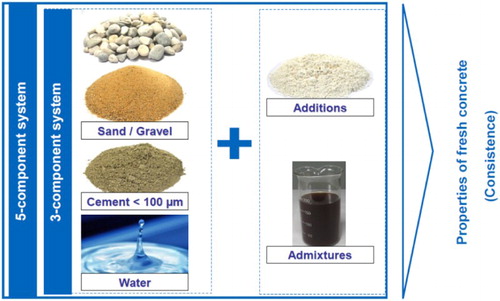
Modern concrete technology makes enormous use of the possibility of higher strength and better durability, both related to lower water content, which is compensated by the incorporation of more chemical admixtures. The addition of fines other than cement has increased the variability of fresh concrete properties. Concrete for deep foundations always has, and still must, obey the principle of good workability at sufficient stability. Concrete used for deep foundations is generally designed to have a low viscosity but high cohesion. As these principle properties are usually contrary when modifying the mix design, the consequence has been to require a minimum slump (or spread) to ensure sufficient viscosity, and a maximum slump (or spread) to ensure a sufficiently high cohesion (to avoid segregation, etc.) This application rule, in general, is fine, and the values put in norms were fine for the old 3-component concrete, but can lead to bad performance with the 5-component concrete (EFFC/DFI Concrete Task Group Citation2015).
A specific ad-hoc working group was established jointly by the DFI and the EFFC in order to conduct a research study aimed at improving existing tremie concreting practices for bored piles/drilled shafts and diaphragm walls. The aim of the research study is to produce Tremie Concrete Guidelines, covering mix design, work preparation, suitability and acceptance, testing and placement, and quality control and is summarised in the EFFC-DFI tremie guide. The following summary covers the current specifications in the U.S. and EU, which considering what precedes will probably evolve in the future.
Concrete specifications in the U.S.
Typical concrete used in deep foundation practice in the U.S. has a compressive strength of 4000–5000 psi (27–34 MPa) and a slump of 7–10 inches (175–250 mm). However, these values can vary per design specification, and some high-flow self-consolidating-concrete (SCC) type mixes are starting to be used. The contractor is typically responsible for the final mix design, although some agencies may have pre-approved mixes. The use of hydration control admixtures and water reducers is common.
Concrete specifications in the EU
Concrete requirements must comply with the specifications of EN 1536: Execution of special geotechnical work – Bored piles. A typical concrete slump ranges between 5 and 9 inches (150 mm ± 30 mm to 200 mm ± 30 mm); however, some high-flow SCC type mixes are starting to be used in Europe as well. Similar to the U.S., the contractor is typically responsible for the final mix design, and, in some cases, is required to perform preliminary compression testing. The use of chemical admixtures and water reducers is increasing.
Execution (construction) related issues
Although construction issues (and specifications or execution codes) are addressed in separate papers, it is appropriate to mention the influence of execution or construction on design practices. The performance of drilled shafts/bored piles is relatively sensitive to construction means and methods (Bottiau Citation2006, Citation2014). It should be pointed out that the diversity of installation methods makes it difficult to generalise the discussion: fully cased piles, partial casing installed by oscillation or vibro-driving and use of different supporting fluids. A number of key factors relating to the execution influence the axial capacity of piles, and these factors raise concerns on both sides of the Atlantic. For many issues, there is a general lack of consensus about the effect of specific construction techniques on design; therefore, the calculation methods used for design do not always distinguish between types of support fluids, use of temporary casing, etc. The reliance upon end bearing for design may include more stringent specifications on bottom hole cleaning before concrete placement.
The study identified common issues with respect to the wide local variations in constructability concerns and the influence of construction techniques (e.g. drilling fluids, use of casing and base cleaning requirements) on foundation performance. These aspects are covered by a number of authors, but the different concerns can be summarised below (after Bottiau Citation2014).
Drilling
The different methods used to drill the hole will play an important role on the contact between the pile and the surrounding soil. If drilled properly within a full casing, while maintaining a sufficient soil plug, the potential loosening of the surrounding soil will be limited but a smoother shaft will be realised. If the pile is excavated under drilling fluid, temporary under-pressures will develop above the drilling tool during excavation or under the grab during lifting (Van Weele Citation1988). If the lifting speed is too rapid, these under-pressures will be detrimental to the shaft stability.
Borehole roughness
In soft rock and cohesive soils, the presence (or absence) of highly degraded smeared rock at the interface will affect the shaft resistance in soft rock, as shown by O’Neill (Citation2001). Some types of shales are also prone to weathering quickly and degrade with increasing time of exposure in an open borehole, with the result that the side resistance can be related to the construction time.
Bottom cleaning
Cleaning of the pile base is of utmost importance to the base resistance, which can represent the majority of the axial resistance for design in many cases. Time-effects of the bored pile construction can exert in this respect an important role, as pointed out by Poulos (Citation2003).
Support fluid
It is recognised that the characteristics of the drilling fluid have influence upon both on execution reliability and on bearing capacity. It is well established that excess thickness of bentonite filter cake can have a profound effect on side resistance, and, in recent years, many authors have noted circumstances in which load tests of bored piles executed under polymer slurry exhibited unit side resistance values significantly higher than that of piles executed under bentonite (Ata and O’Neill Citation1998; Brown Citation2002; Brown et al. Citation2002; Lam et al. Citation2010). Techniques used for base cleaning should be treated differently according to the drilling fluid (O’Neill and Reese Citation1999; Brown et al. Citation2010).
A major factor that can potentially influence the structural performance in flexure is the presence of major and minor flaws in pile shaft (structural integrity). For this reason, close inspection and post-construction integrity testing are often required for critical foundations or where lack of structural redundancy exists. When comparing common practices between the U.S. and the EU, the following can be identified:
Practice in the U.S.
A common concern of designers relates to the use of permanent and/or temporary casing and to the impact on axial resistance. Likewise, bottom cleaning and inspection requirements are important for drilled shafts with high-design base resistance; however, only a few local areas customarily try to obtain a dry excavation to focus on inspection of the shaft base. Polymer slurry has broad acceptance and widespread use; however, some areas of the U.S. preclude polymer in favour of bentonite, and some have the reverse opinion; hence, controversies in the construction communities remain.
Practice in the EU
Practice in the EU is globally governed by the European Execution Codes eidted by the European Committee for Standardization (Citation1999). In Europe, bottom cleaning requirements are one of the most common issues related to pile integrity. In addition, there is a large variation of practice regarding the use of fully cased bored piles or piles bored under bentonite. Contrary to the U.S., polymer slurry is rarely used. Time-effects (elapsed time between cleaning and concreting) are subject to caution. Low cost practices, such as dry drilling, may apply locally for commercial projects.
Inspection and testing
It is relevant to mention the effect of the anticipated level of inspection and testing on the design. Clearly, inspection is needed to confirm that the materials encountered are consistent with the design. However, the level of involvement of the design professionals in the inspection process can vary widely depending upon the type of project and the owners or building officials. Where designers have low expectations of confirmation by rigorous inspection during construction, there is a tendency to design the piles very conservatively to cover possible variations in ground conditions. Where inspection is robust and site-specific load tests are planned, the design may be less conservative and may utilise higher resistance factors (lower factors of safety). It is important to consider that load tests must be representative of the typical ground conditions at the site and that accommodations for variations in ground conditions are still necessary. In general, it is noted that the trend in both the U.S. and EU is for more stringent emphasis upon post-construction integrity testing for many applications, reflecting increased demands on drilled shaft/bored pile foundations from a structural standpoint.
Summary
Several major trends have been identified that are common with respect to the design of foundations using bored piles/drilled shafts in the U.S. and EU. These include increasing complexity in the project demands and applications, as well as more stringent testing and quality assurance requirements. The design codes differ in some respects, but the most striking similarity between the U.S. and EU is the tendency for local (national in the case of EU) variations to persist in the implementation of design practices. Some of the variations reflect geologic differences, but much of the inconsistency in design practice appears to be simply relics of the evolution of local practice that are not easily relinquished. Other common issues identified include the wide local variations in constructability concerns with respect to concrete mix characteristics, reinforcement details and the influence of construction techniques (e.g. drilling fluids, use of casing and base cleaning requirements) on foundation performance. Designer concerns related to these issues are typically reflected in construction specifications or execution codes.
References
- ACI Committee 318. 2014. Building code requirements for structural concrete: (ACI 318-14); and commentary (ACI 318R-14). Farmington Hills, MI: American Concrete Institute.
- American Association of State Highway and Transportation Officials. 2016. Aashto LRFD bridge design specifications. Washington, DC, American Association of State Highway and Transportation Officials.
- Ata, A. and O’Neill, M. W. 1998. Sidewall stability and side-shear resistance in bored piles constructed with high molecular-weight polymer slurry. Proceedings of the 3rd International Geotechnical Seminar on Deep Foundations on Bored and Auger Piles, Balkema, Rotterdam, 111–117.
- Beckhaus, K. 2016. Concrete for Deep Foundations. ISSMGE - ETC 3 International Symposium on Design of Piles in Europe. Leuven, Belgium, 28 & 29 April 2016.
- Bieniawski, Z. T. 1989. Engineering rock mass classifications: a complete manual for engineers and geologists in mining, civil, and petroleum engineering. New York, NY: Wiley-Interscience, pp. 40–47 . ISBN 0-471-60172-1.
- Bottiau, M. 2006. Recent evolutions in deep foundation technologies-General report. Proceedings of the 10th International Conference on Piling and Deep Foundations, Amsterdam.
- Bottiau, M. 2014. Installation parameters, pile performance and importance of testing. Proceedings of the 12th International Conference on Piling and Deep Foundations, Stockholm.
- British Standards Institution. 1995. Eurocode 7; London, British Standards Institution.
- British Standards Institution. 1996. Eurocode 8: design provisions for earthquake resistance of structures; London, British Standards Institution.
- Brown, D. A. 2002. The effect of construction on axial capacity of drilled foundations in piedmont soils. Journal of Geotechnical and Geoenvironmental Engineering, ASCE, 128(12), 967–973. doi: 10.1061/(ASCE)1090-0241(2002)128:12(967)
- Brown, D. A., Muchard, M. and Khouri, B. 2002. The effect of drilling fluid on axial capacity, Cape Fear River, NC. Proceedings of the Deep Foundations Institute 27th Annual Meeting, San Diego.
- Brown, D., Turner, J. and Castelli, R. 2010. Drilled shafts: construction procedures and LRFD design methods. In: FHWA/NHI publication 10-016, reference manual and participants guide for national highway institute. Course 132014, 972.
- EFFC/DFI Concrete Task Group. 2015. The EFFC/DFI Best Practice Guide to tremie Concrete for Deep Foundations. http://www.effc.org/content/uploads/2016/02/EFFC_Tremie_Concrete_Guide_Final.pdf.
- EN 1997-1. 2004. “Eurocode 7: Geotechnical design – Part 1: General rules” Authority: The European Union Per Regulation 305/2011, Directive 98/34/EC, Directive 2004/18/EC.
- EN 1997-2. 2007. “Eurocode 7: Geotechnical design – Part 2: Ground investigation and testing” Authority: The European Union Per Regulation 305/2011, Directive 98/34/EC, Directive 2004/18/EC.
- European Committee for Standardization. 1999. EN 1536: Execution of Special Geotechnical Work. Deutsches Institut für Normung e. V.
- Huemmeler, L., Hoffmann, N. and von Jutzrenka B. 2014. A new piling technology for Europe’s new tallest building: the Lakhta tower. Proceedings of the 12th International Conference on Piling and Deep Foundations, Stockholm.
- International Code Council. 2011. 2012 international building code; Country Club Hills, IL, ICC.
- Lam, C., Troughton, V., Jefferis, S. and Suckling, T. 2010a. Effect of support fluids on pile performance – a field trial in East London. Ground Engineering, 43(10), 28–31.
- Marinos, P. and Hoek, E. 2000. GSI – A geologically friendly tool for rock mass strength estimation. Proceedings of GeoEng2000 Conference, Melbourne, 1422–1442.
- O'Neill, M. W. 2001. Side resistance in piles and drilled shafts, the 34th terzaghi lecture. Journal of Geotechnical and Geoenvironmental Engineering, ASCE, 127(1), 1–16. doi: 10.1061/(ASCE)1090-0241(2001)127:1(3)
- O’Neill, M. W. and Reese, L. C. 1999. Drilled shafts: construction procedures and design methods, Report No. FHWA-IF-99-025, FHWA, Washington, DC, 758.
- Poulos, H. 2003. Analysis of soil extraction for correcting uneven settlement of pile foundations. Twelfth Asian Regional Conference on Soil Mechanics and Geotechnical Engineering (12ARC), Asia: World Scientific Publishing.
- Spearin v. U.S. 1918. (248 U.S. 132 (1918)), 135–136.
- Van Weele, A. F. 1988. Cast-in-situ piles – installation methods, soil disturbance and resulting pile behavior. Proceedings, Deep Foundations on Bored and Auger Piles, Van Impe (ed.), Balkema, Rotterdam, 219–226.
- Zaghouani, K., Chouikha, A. and Haffoudhi, S. 2013. Difficulty execution of large diameter deep piles in soft soils. Proceedings of the 18th International Conference on Soil Mechanics and Geotechnical Engineering, Paper No. 3058.