Abstract
Geothermal (ground source) heat pumps (GHP) and permeable pavement systems (PPS) have demonstrated their effectiveness in both industry and academic research during recent decades. To meet the rising demand for sustainable, recyclable and energy efficient techniques, research has focused on the combination of techniques to enhance existing or develop new applications.
This paper reports on an experimental programme that combined GHP with PPS for nutrient removal and system energy balancing. Experimental data collected over a 3-year period have provided evidence of highly efficient removal rates of up to 99% for ammonia–nitrate and biochemical oxygen demand; and 96% removal rates were obtained for orthophosphate–phosphorus. This paper also contains energy efficiency ratio (EER) and coefficient of performance (COP) calculations. Cyclic heat removal and heat rejection allowed for stable temperature and pump COP and EER sustainability. The results prove that PPS systems are appropriate for GHP installation, delivering high and stable pollutant removal with EER efficiencies between 1.5 and 5.5.
The combination of GHP with PPS has the potential to provide a new sustainable and eco-friendly practice.
Nomenclature
| BOD | = |
biochemical oxygen demand (mg/l) |
| COP | = |
coefficient of performance (dimensionless) |
| COPheating | = |
coefficient of performance in heating mode (dimensionless) |
| COPcooling | = |
coefficient of performance in cooling mode (dimensionless) |
| Cp,w | = |
specific heat capacity of the water (kJ/kgK) |
| EER | = |
energy efficiency ratio (dimensionless) |
| GHP | = |
geothermal (ground source) heat pump |
| HDPE | = |
high-density polyethylene |
| Ic | = |
current for the compressor and pump (A) |
| Ip | = |
current for the pump (A) |
| mw | = |
mass flow rate of the water (kg/s) |
| NH4 | = |
ammonia-nitrogen |
| PAH | = |
polycyclic aromatic hydrocarbons |
| PE | = |
polyethylene |
| PO4 | = |
ortho-phosphate-phosphorus |
| PP | = |
polypropylene |
| PPS | = |
permeable pavement systems |
| Qheat supplied | = |
thermal energy supplied to system (kW) |
| Qheat rejected | = |
thermal energy leaving system (kW) |
| SS | = |
suspended solids (mg/l) |
| SUDS | = |
sustainable urban drainage system |
| SWT | = |
saturated water temperature (°C) |
| THB | = |
total heterotrophic bacteria (counts/ml) |
| Tmax | = |
maximum temperature at the hot reservoir (°C) |
| Tmin | = |
minimum temperature at the cold reservoir (°C) |
| t | = |
day/month of year |
| tambient | = |
ambient temperature for indoor rigs (°C) |
| W(net work input) | = |
power and energy input from compressor and pump (kW) |
1. Introduction
Water and energy are two of our most essential and precious resources and they are also two of the most critical environmental concerns facing the world today. Projections forecast a growing demand for water and energy in the future due to population growth, the need to improve living standards and the high levels of resource consumption in fast growing economies such as India and China (German Advisory Council on Global Change Citation2003). Supplies of potable water and fossil fuel energy sources are limited. Hundreds of millions of humans currently lack adequate access to clean and potable water. During the past century, the world's population has tripled, but water use has increased six fold. Recent estimates for energy consumption in developing countries show that consumption is expected to increase exponentially by the year 2020 as a result of economic development targets that have already been set (Lior 2008).
Water and energy are often inseparably coupled and a lack of access to energy often restricts the availability of water. Sustainable development depends on the efficient use of these two resources, especially on the widespread use of clean and renewable energy (Asif and Muneer Citation2007). To meet global challenges and strategic demands, it is necessary to foster projects that incorporate sustainable techniques that will counter climate change and water scarcity (Dincer and Rosen Citation1999).
2. Background
2.1 Overview
The shortage of water and energy resources is recognised as a critical issue in many parts of the world. In order to identify the needs and obstacles relating to water and energy initiatives at the residential level, and to initiate appropriate solutions, the Institute of Infrastructure and Environment, (The University of Edinburgh, Scotland, UK) in partnership with Hanson Formpave (Heidelberg Cement Group, San Diego, CA, USA) implemented a 5-year pilot project to operate between April 2006 and April 2011. This project will generate environmental and social benefits by encouraging the switch to renewable energy systems, such as ground source heat pumps (GHP), and water reuse. In the long term, carbondioxide emissions can be reduced by substituting renewable energy for energy generated from fossil fuel sources (Dincer and Rosen Citation1999). The novel technology reported in this paper focuses on a combination of GHPs and sustainable urban drainage systems (SUDS) as a tool for water harvesting and recycling and combines it with renewable energy. During the last decade, GHPs have received considerable attention in Europe and North America as alternative renewable energy sources for residential/commercial heating and cooling applications (Healy and Ugursal Citation1997).
This paper presents an analysis of the performance of an integrated geothermal heat pump and permeable pavement system.
2.2 Permeable pavements systems
Permeable pavement systems (PPS) are recognised as valuable tools for water recycling and management when applied as one of the available SUDS techniques (Carmon et al. Citation1997, Chocat Citation2002). Such tools are used in various environmental applications for the removal of pollutants and they are the subject of academic experimental research (Pratt et al. Citation1999, Coupe Citation2000, Brattebo and Booth Citation2003). The main components of PPS fall into four groups: pavers and bedding layer, unsaturated zone of base material, saturated zone of base material and sub-grade (James and von Langsdorff Citation2003). These groups can consist of different aggregates and aggregate-mixed substances (Scholz and Grabowiecki Citation2007).
The lifespan of PPS depends on an appropriate design to accommodate the amount of stress put onto the pavement surface (Omoto et al. Citation2003). Research conducted by the Department of Civil Engineering at the University of Washington, Seattle, WA, USA (Brattebo and Booth Citation2003) showed that, after 6 years of intensive usage (car park space), tested parking bays did not show any major signs of wear. The infiltration rates and pollutant removal rates were similar to freshly installed applications. However, it is important to recognise that the problem of clogging can arise as infiltration rates decrease after 20–25 years of operation (Shackel and Pearson Citation2003). This highlights the importance of PPS surface maintenance.
PPS have proved their efficiency in removing pollutants such as hydrocarbons (used motor oil; Pratt et al. Citation1999, Newman et al. Citation2004), metals (Dierkes et al. Citation1999, Napier Citation2005) and nutrients (Coupe et al. Citation2005). Moreover, PPS can remove up to 90% of the total suspended solids (SS) present (Shackel et al. Citation2003). In the research reported in this paper, it was proven that success rates above 90% could be obtained for other water quality parameters such as biological oxygen demand (BOD), total heterotrophic bacteria or nutrients including ammonia–nitrate and orthophosphate–phosphorus, as explained in more detail in Section 5.2.
The experimental system was developed with an additional horizontal layer to increase microbial colonisation, subsequently improving pollutant removal rates. The material used for this layer was Inbitex® geotextile composed of polyethylene (PE)–polypropylene (PP) fine fibres. Geotextiles are one of the most essential components within PPS and their importance has been discussed in the literature (Newman Citation2003, Omoto et al. Citation2003, Spicer et al. Citation2006). They extend the durability and structural performance of the sub-base (Omoto et al. Citation2003) enhancing microbial growth and providing increased pollutant removal rates (Coupe Citation2004).
2.3 Geothermal (ground source) heat pumps
GHPs are a well-recognised source of renewable energy (Lund et al. Citation2004, Curtis et al. Citation2005) and this established technology provides high efficiencies for heating and cooling by employing the enormous renewable storage capacity of the ground (Curtis et al. Citation2005). GHPs are increasingly recognised as an alternative to fossil fuel systems and, as a result, this technology offers a significant reduction in the carbondioxide emissions associated with cooling and heating applications for buildings (Healy and Ugursal Citation1997, Esen et al. Citation2006).
GHPs are seen as a sustainable technology because they recover and recycle thermal energy from the soil. They use the relatively constant temperature of the earth to provide heating, cooling and hot water for buildings. They transform the earth's energy into usable energy by extracting heat energy from the ground for heating purposes or by using a body of water to reverse the process for cooling purposes (Healy and Ugursal Citation1997, Hepbasli Citation2005).
A GHP system consists of three major components: a heat pump, an earth connection and an interior heating or cooling distribution system (Kavanaugh and Rafferty Citation1997). The heat pump transfers the heat between the heating/cooling distribution systems. The earth connection is where heat transfer between the GHP system and the soil occurs. The heating/cooling distribution system delivers heating or cooling from the heat pump to the building. Various arrangements, such as horizontal, vertical, looped or submerged designs can be utilised depending upon variables such as the type of soil, geology and the area of available land for installations (Lund et al. Citation2004, Curtis et al. Citation2005).
3. Research objectives
The main objectives of the research reported in this paper were:
-
to combine two sustainable techniques by designing an integrated PPS and GHP system;
-
to assess the integrated system's performance, with regard to microbial activities under varying temperature patterns;
-
to test for water quality and water reuse; and
-
to evaluate energy saving and the system's energy efficiency.
4. Experimental equipment and operation
4.1 Experimental set-up
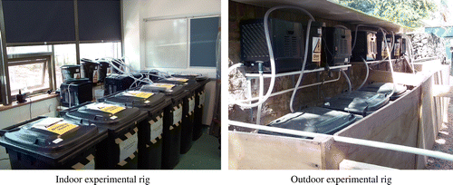
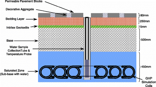
The system was constructed using indoor and outdoor experimental rigs connected to simulate parallel GHP operation (Figure ). The indoor PPS was composed of six bins placed in a temperature-controlled room with a mean ambient temperature of 15°C. The corresponding outdoor rig was submerged in the ground where it was subjected to ambient atmospheric and soil temperature conditions. Each bin was partly filled with inflow water and operated in batch flow mode; this was intended to simulate real-life car park and pavement run-off conditions (Scholz Citation2006). The high-density polyethylene bins were of 240 l capacity and provided impermeable, tanked, PPS simulation and ease of water collection.
Commercially available pre-washed aggregates were used for the sub-base construction. The aggregate sizes were determined and provided by the manufacturer (Formpave Citation2004) in accordance with British Standards (British Standards Institution BS Citation882 1992, Highways Agency Citation2005); e.g. crushed gravel and rock with defined edges and sizes between 10 and 63 mm.
A typical composition of layers comprised a lower sub-base (25 cm), an upper sub-base (10 cm), a geotextile layer, a clean 0.5 cm stone layer (5 cm) and, finally, paving blocks (8 cm) at the top (Formpave Citation2004), as summarised in Table . The depth of the standardised sub-base was doubled, to 50 cm, for the purpose of this research in order to integrate GHP simulation, as the GHP had to be fully submerged in water to operate efficiently. A system containing space filled with porous media, under a constant head of water pressure, delivers conditions similar to submerged systems containing GHP installations (Water Furnace Citation2007), and provides a desirable conductivity to allow for sufficient heat transfer.
Table 1 Composition of layers within the experimental PPS.
The second layer, located in the upper sub-base, contained stones with diameters between 0.5 and 2 cm to a depth of 10 cm. The porous PE–PP Inbitex® geotextile (Collins et al. Citation2002) was placed in the top part of the upper base, as it was the most suitable area for immediate microbiological development. Either Inbitex® on its own or Inbitex® composite was used in the bins (Table ). The impermeable layers (composite) were overlapped to allow for water percolation into the bottom parts of the bin. It was also essential that the coils were constantly submerged in water. Impermeable layers were used to provide water evaporation protection from the sub-base. This technique is used in real-site applications in warm countries such as Spain and Australia. In the reported experiments, additional protection against evaporation during the heating cycle was provided. At a later stage in the experiments, it was established that composite layers were unnecessary under UK weather conditions (weak sub-base evaporation during warm seasons).
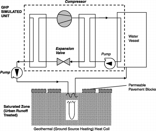
The system's installation incorporated reinforced 5-mm PP tubes placed within the lower sub-base. Their total length (seven to nine loops) was approximately 10 m. Both ends of each tube were located in a plastic water vessel. One of the ends was connected to the pump and the other end was used for water discharge into the vessel. This arrangement provided closed circulation of water (Figure ). Two rigs were operated under controlled (indoor rig) and uncontrolled (outdoor rig) conditions as there was a need for energy input to simulate GHP workability.
4.2 Operation of the simulated GHP heating and cooling elements
In existing large-scale industrial applications, the source of energy for the heating or cooling system is provided from natural soil or a water reservoir (Figure ; Water Furnace Citation2007). This arrangement could not be reproduced for the experiments due to cost constraints and so a different heat transfer system was used, albeit one that mimicked the components of a practical GHP. During the winter of the first year of research, heat was provided to the sub-base, resulting in a relative increase in temperature. This arrangement simulated real-life conditions of the out-flowing water for the inside rig, and increased relative temperature differences for the outside rig. During warm periods, the opposite arrangement was used, and this resulted in cooling of the sub-base. Reversed water temperature conditions were used to simulate inflow water (warm in summer and cold in winter).
The same arrangement was applied for the outside rig. Both annual simulation cycles provided water quality data for the inflow and outflow and temperatures. Moreover, the experimental procedure provided smooth transitions from balanced temperature conditions to very extreme ones. In practice, indoor ventilation systems and GHP are fully automated (Collins et al. Citation2002).
The heating and cooling periods for the rigs depended on the programmed duration of set timers. The timers switched the required elements either on or off. The elements heated up or cooled down the water within the coils. The coolers prevented the temperature from decreasing by less than 5°C, and the thermostats prevented overheating by switching the heaters off when a temperature of 22°C was reached.
Considering research needs and typical local temperature fluctuations, heating and cooling cycles were set to simulate a car park servicing a supermarket in Scotland. Switching patterns were determined from surveys carried out in supermarkets in 2006 and through discussions with professionals operating such car park systems. Several switching patterns were considered by the researchers, the most efficient were selected for simulation and energy saving analysis and these are presented in Table . The switching modules were programmed up to six times within a 24-h cycle.
Table 2 Heating and cooling switching patterns during different seasons.
It was assumed that large-scale commercial sites and office buildings would usually prefer the option to switch off heating and cooling devices to reduce the overall energy bill. It is very important to emphasise that the energy for heating at real-life sites would be provided from heat sinks such as natural surroundings (e.g. sub-base of PPS, soil and lake) and the described switching patterns were created for the purpose of this research in which external energy was introduced into the systems.
5. Performance of simulated GHP with integrated PPS
5.1 System performance concerning energy
The simulated GHP system that was analysed can be assumed to follow a reversed cycle (Carnot cycle) to supply heat at the elevated temperatures at the expense of work done by the GHP (Cengel and Boles Citation2007). The ratio of output to input measures the performance of a heat pump, namely heat supplied and heat rejected to work input.
To assess the energetic efficiency of the GHP process, the ratio of the available useful heat produced by the system is compared to the energy that must be fed into the system (Wark Citation1999). The efficiency of a GHP unit is described by the coefficient of performance in the heating mode (COPheating) and the energy efficiency ratio (EER)/COPcooling in the cooling mode (respectively in Europe), which is the ratio of the output energy divided by the input energy (work done by compressor and pumps). This has been shown to be the most appropriate method for assessing the energetic quality of a system (Healy and Ugursal Citation1997, Hepbasli Citation2005). In essence, COP and EER depend on the difference in temperatures between the source of heat and the heating system that needs to be overcome (Hepbasli and Akdemir Citation2004).
For the experimental water-source GHPs, the EER or COPcooling is the index which defines the cooling performance. The heating performance during the heating mode is calculated by the coefficient of performance (COPheating) (Hepbasli Citation2005, Cengel and Boles Citation2007).
According to the first law of classical thermodynamics, in a reversible system (Cengel and Boles Citation2007):
The heat supplied by the GHP unit in the heating mode can be described by the equation:
The negative heat removal rate indicates that heat is leaving the system.
The COP in a heating mode for a reversible inverse Carnot cycle and the EER (Wark Citation1999, Cengel and Boles Citation2007) for the cooling mode is given by
By substituting W
net work input from Equation (Equation6), into Equation (Equation4
), can be rearranged to give
In addition, a corresponding substitution for Equation (Equation5) gives
By using rearranged Equation (Equation9) (
) and substituting it into Equations (Equation7
) and (Equation8
Equations (Equation7
) and (Equation8
), the general COP and EER (or COPcooling) can be expressed as
And, similarly:
Using the maximum and minimum temperatures measured in the experimental rigs, and assuming the simulated system operates in the ideal Carnot cycle, the overall COP for the heating cycle and EER for the cooling cycle were plotted against time. The saturated temperatures at the base were also measured and plotted against time.
5.2 Pollutant removal by PPS with GHP installations
Gully pot liquor mixed with tap water and dog faeces (van Der Wel Citation1995, Environmental Campaigns Citation2003) were used in the experimental rigs for artificial spiking of the PPS. Such mixtures mimic the most extreme conditions that may occur in practice. Gully pot liquor provides all possible pollutants that occur in real-site operation and the gully pot is a biochemical reactor in which pollutants are released after acidic dissolution and sediment maturation (Scholz and Grabowiecki Citation2007). A gully pot chamber also comprises tarmac washout which contains metals and polycyclic aromatic hydrocarbons. Primary sludge forms in the chamber and, during increased precipitation, this is released into traditional waste water drainage systems (Memon and Butler Citation2002).
Because of the designed role of the gully pots they have a direct impact on water introduced into the sewers as well as water streams, as the biochemical processes increase the amount of dissolved pollutants in the liquor which is washed out especially during storm events (Memon and Butler Citation2002). Because of the high gully pot liquor strength it was diluted in 1:10 ratio with tap water.
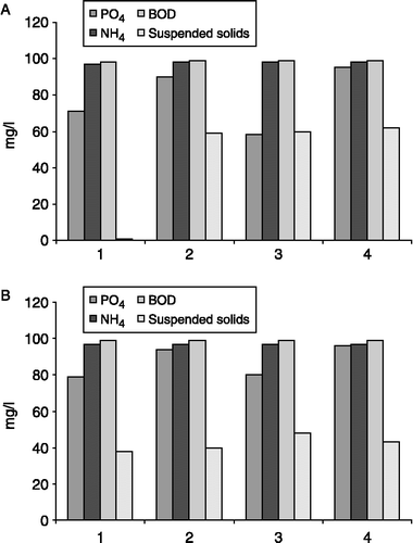
The aims of the research included the analysis of the pollutant removal rate from PPS. For the purpose of this paper, SS, BOD, ammonia–nitrogen and ortho-phosphate–phosphorus removal rates were determined and the results are presented in Figure .
Removal rates were calculated using the following formula:
SS showed the highest variability in seasonal removal rates. For the outside systems, the lowest SS removal rate was obtained at bin 1, with an average of 51%. This resulted in the introduction of external pollutants into the bin's sub-base. Other removal rates varied between 40 and 62% for both rigs. It is important to emphasise that these values represent a water-sediment mixture which would never be released into water courses. Therefore, ‘real’ values are relatively lower; e.g. 90% SS reduction (Shackel and Pearson Citation2003; measured at the overflow outflows). There is no visible trend connected with seasonal changes in the inside rig and removal rates were relatively stable throughout the study period. For the outside system, the highest removal rates occurred during the GHP heating (heat introduction) season.
The highest removal rates recorded in both systems were for BOD and ammonia–nitrate removal where removal rates reached values of 97–99%. No visible seasonal change was recorded for the inside rigs. A decrease in removal efficiency was recorded mainly for cold months such as March and November 2007, and February 2008 for ammonia–nitrogen, although the rates were still above 80%. For the outside BOD, the worst removal rates were recorded for summer 2007, although the removal rates did not drop below 85%.
Orthophosphate–phosphorus reduction values varied between 58 and 95% for the outside rig and 79–96% for the inside rig. Lower removal efficiency averages were found for bins 1 and 5 inside and the corresponding bins outside. This was caused by additional pollutant additions (dog faeces). High-visible fluctuations were not recorded for the remaining bins where average reductions above 60% were found for both rigs.
Recorded levels of collected samples fit well within European Union Wastewater Standards (EU Citation2008), when discussing nutrients or BOD values. This provided evidence for high PPS efficiency and performance, undisturbed by GHP installation.
6. Experimental results
6.1 Overview
The experimental results show the performance characteristics for the simulated integrated GHP–PPS system. The ambient temperatures varied for the PPS, as average relative humidity affected the external rigs. The geothermal heat pump system was configured for combined cooling and heating modes for different seasons throughout the year. The performance results for the ground-water temperature variations and the heat pump COP and EER for the first two-and-half years are shown in Figures .
6.2 EER – cooling mode
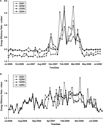
The EER measures the steady state cooling efficiency of the geothermal heat pump, and the higher the EER, the more efficient the unit. The results for 2 years of the sampled data set of EER versus time, for two sets of cooling cycles, are shown in Figure . The cooling operation modes were employed for the different seasons throughout the year. The EER shows a continuous increase due to accumulation of the heat rejected from the system.
As the EER increases, less heat is supplied by the GHP or more heat is rejected by the system for the same amount of mechanical and electrical energy consumed. However, it should be noted that the total cooling energy consumption is much smaller in relation to the heating energy consumption. Figure indicates a lower performance index when compared to the heating cycles (Figure ), both for the outdoor and indoor rigs.
As a GHP capacity size increases the heat pump energy is rejected and EER increases. The actual performance of the system during the cooling mode is a function of the water temperature produced by the GHP. It is clear from the performance graphs that the simulated GHP can be categorised as acceptable, when compared to values of the US Department of Energy ranging from 3 to 5 for heat pumps in a cooling cycle (United States Department of Energy Citation2001).
The heat rejection rate, which is represented by the EER performance index factor, represents the values of cooling performance found in Europe and North America. The values for both indoor and outdoor experimental rigs were found to be in the range of 1.3–1.8 for indoor bins and 1.5–5.5 for outdoor bins, demonstrating that the system design was correct and efficient in terms of GHP installation.
The performance of the GHP during the cooling cycle is such that at relatively moderate ambient temperatures of 15.0°C for the indoor rigs the constant heat transfer resulted in a lower EER, which caused a reduction in the cooling capacity when compared to the outdoor rigs (EER varying from 1.5 to 5.5). This performance is illustrated in Figure .
This GHP would operate more efficiently for temperatures below 11.0°C with the outdoor GHP having performed 35–50% more efficiently when compared to the indoor GHP.
6.3 COP – heating mode
COP is a measure of a heat pump's efficiency for heating applications and the higher the COP, the more efficient is the heat pump.
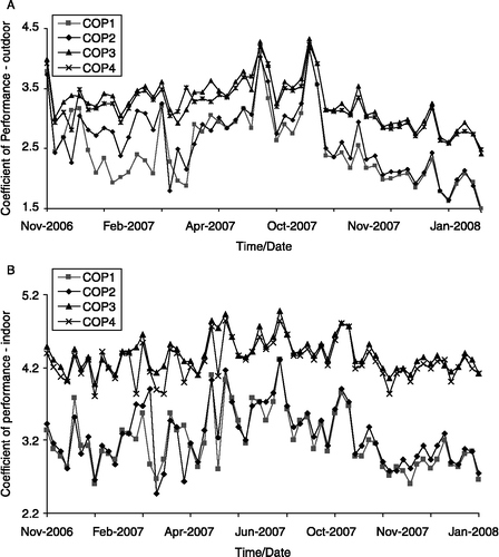
To investigate the performance of the GHP system further, the heating operation modes were employed for the different seasons throughout the year. The ground source heat for the outside and inside rigs followed a similar pattern of temperature rise, as was the case for the cooling mode. Figure shows the COP profile versus time for the inside and outside systems. Heating performance rather than cooling performance should be considered when optimising GHPs (Healy and Ugursal Citation1997).
COP is a key parameter for GHPs. The graphs of COP vs. time for both indoor and outdoor rigs illustrate benchmarks for the system in terms of the heating capacity. It is apparent from Figure that the system can be categorised as acceptable. The saturated water temperature (SWT) of the GHP unit will be higher than the normal temperature of the earth during this mode of operation. The actual performance of the system is a function of water temperature produced by the GHP. The values of COPheating were found to lie between 2.3 and 4.5 for the indoor rigs and between 1.5 and 4.4 for the outdoor rigs. It was noted that the COP values change slightly from 1.5 to 4.5 for both the indoor and outdoor systems. The system's COP varies with the difference between the SWTs. This difference can simply be defined as the temperature lift, e.g. the temperature difference between the source and the sink. The lower this temperature difference, the higher the COP. This trend is shown in Figure and the results presented indicate that the COP of the heat pump increases with increasing temperature of the water entering. Therefore, a smaller temperature difference enhances the overall COP of the heat pump. Again by comparison based on the values of the US Department of Energy (Citation2001), the COP heating values for equivalent systems should be in the range of 4–6 (Lund et al. Citation2004). The performance of the simulated system proved comparable to practical GHP units. The variation in performance of the simulated heat pumps, when compared to actual GHP's, is due to the energy requirements, size, heating and cooling loads as well as the average annual energy transfer per square metre of area, which represents a small-scale experiment in comparison to industrial and commercial GHP applications.
Table presents the average heating and cooling performance index calculated for the GHP system. These values are based on the GHP working all year round in the heating or cooling mode. The simulated geothermal heat pump design is thus feasible when it is applied to cooling and heating modes of operation.
Table 3 Average COP and EER performance index ratios for the GHP system.
6.4 Temperature analysis – SWT
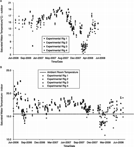
Figure shows the SWT of the base for four outdoor rigs from September 2006 to June 2008. The temperature values were recorded twice per week, and are plotted versus time. The SWTs ranged between 5 and 21°C for both heating and cooling cycles. The figure presents the sample set of experimental results for the geothermal heat pump's performance. The graph illustrates SWTs for the heat pump unit at the base of the experimental rig. These results were recorded during the transient-to-steady state period of operation of the geothermal heat pump. For the period from October 2006 to January 2007, there was a drop in the average temperatures during the heating cycle. This was attributed to convective heat transfer to the water due to air temperature fluctuations in Edinburgh.
The SWT is the single most representative parameter for GHPs as it couples effectiveness and heat pump cooling and heating load applications. In other words, the actual performance of the experimental rigs is a function of the water temperature produced by the GHP. Figure (a) shows the daily and monthly variations of temperatures and illustrates the point of lowest water temperature, which typically occurs at the minimum of 5°C for the cooling cycles. The maximum SWT over the period was 20.5°C.
For the indoor temperatures (Figure (b)), the ambient room temperatures were kept at approximately 15°C for control purposes. The dataset follows cycles of heating and cooling modes, the lowest temperatures during the cycles recorded were approximately 12°C and the highest recorded value was 23.5°C. The warm ‘summer’ (cooling mode) temperatures, which are the load side entering water temperatures at the heat pump, ranged between 12 and 18°C. The corresponding cold temperatures, which are the load side temperatures of the water leaving the heat pump, ranged between 10 and 13°C.
For ‘winter' (heating mode), the hot temperatures of the water leaving the heat pump ranged between 22 and 25°C and the cold temperatures of the entering water at the heat pump ranged between 4 and 5°C.
The graphs in Figure show the minimum and maximum temperature profiles of water in the GHP for the 2-year period. The main difference between the outdoor and indoor rigs is the normal working temperature of the outside environment. In the summer, the water of the outdoor rigs had a lower temperature than that of the indoor GHP system; whereas in winter, colder temperatures were experienced for the outdoor rigs whilst the indoor temperature remained constant at 15.5°C.
Variations for the different bins during the heating and cooling modes were due to the imbalance between annual heating load and annual cooling load, where more thermal heat was stored at the base of the rigs over time. This led to an increase in the heating efficiency and to a loss of cooling efficiency over time.
7. Conclusions
An experimental programme was conducted to investigate a simulated combined PPS and GHP system that has operated satisfactorily since 2006. The effects of temperature, climatic conditions and operating parameters on the system's performance were investigated.
The average removal rate values ranged between 80 and 90% for BOD, ammonia–nitrogen and ortho-phosphate–phosphorus. However, SS removals varied between 40 and 60%. The only failure (bin 1 outside) was caused by technical problems and the subsequent need for the replacement of the sub-base. The PPS pollutant removal rates and the values of EER and COP for the HHP provide verification that both sustainable techniques work in harmony as a hybrid system.
Results of the studies based on the assumed properties of the site and the local weather conditions in Edinburgh, UK, prove that the GHP used for cooling and heating is a useful and sustainable long-term tool. The cyclic heat rejection to, and heat removal from, the experimental indoor and outdoor rigs helped to maintain an acceptable steady temperature and sustained heat pump COP and EER. Therefore, it can be concluded, as demonstrated by the performance results, that it is feasible to adopt the use of GHP for cooling and heating within a PPS installation.
GHP systems provide stable performance in terms of energy efficiency, environmental impacts, service life and maintenance requirements, which are important factors in the choice of cooling and heating systems for engineers and planners. Thus, they have a high potential for application in urban areas when combined with sustainable water reuse systems. Furthermore, the economic advantage provided by this system, combined with its minimal environmental impact, should promote the proliferation of such systems in the near future.
Acknowledgements
The authors would like to acknowledge Hanson Formpave Ltd which sponsored Mr Tota-Maharaj's and Mr Grabowiecki's PhD projects. The researchers would like to thank Dr Stephen Coupe from Coventry University for his participation in technical discussions and advice concerning the experimental set-up. Dr Martin Crapper provided advice on the preparation of the paper.
Additional information
Notes
References
- Asif , M. and Muneer , T. 2007 . Energy supply, its demand and security issues for developed and emerging economies . Renewable and Sustainable Energy Reviews , 11 : 1388 – 1413 .
- Brattebo , B.O. and Booth , D.B. 2003 . Long-term stormwater quantity and quality performance of permeable pavement systems . Water Research , 37 : 4369 – 4376 .
- British Standards Institution BS 882. 1992. Specification for aggregates from natural sources for concrete [online]. Available from: http://www.bsigroup.co.uk [Accessed 30 June 2008]
- Carmon , N. , Shamir , U. and Meiron-Pistiner , S. 1997 . Water-sensitive urban planning: protecting groundwater . Journal of Environmental Planning and Management , 40 : 413 – 434 .
- Cengel , Y.A. and Boles , M.A. 2007 . Thermodynamics: an engineering approach , Berkshire, UK : McGraw-Hill Education .
- Chocat , B. 2002 . “ Sustainable management of water in cities ” . In Challenges of the new water policies for the XXI century , Valenzia : Universidad Internacional Menendez Pelayo . 29–31 October 2002
- Collins , P.A. , Orio , C.D. and Smiriglio , S. 2002 . Geothermal heat pump manual [online]. City of New York, Department of Design and Construction. Available from: http://www.ci.nyc.ny.us/html/ddc/html/ddcgreen/geotherm.html [Accessed 30 June 2008]
- Coupe, S.J., 2000. Water quality within permeable pavements: chemical and microbiological analysis laboratory and field based studies. Unpublished report. Coventry University, School of Science and the Environment
- Coupe, S.J., 2004. Biodegradation and microbial ecology within permeable pavements. Unpublished report. Coventry University, School of Science and the Environment
- Coupe , S.J. , Lowe , T. , Smith , H.G. and Eastwood , I.W. 2005 . “ The effects of nutrients on the biodegradation of used and unused oil in permeable pavement systems ” . In Third National Conference on Sustainable Drainage. Incorporating 27th Meeting of Standing Conference on Stormwater Source Control , Coventry : Coventry University, School of Science and the Environment . 20–21 June 2005
- Curtis , R. , Lund , J. , Sanne , B. , Rybac , L. and Hellströ , G. 2005 . Ground source heat pumps – geothermal energy for anyone, anywhere: current worldwide activity . World Geothermal Congress , 24–29 April 2005. Antalya
- Dierkes, C., Holte, A. and Geiger, W.F., 1999. Heavy metal retention within a porous pavement structure. Unpublished report. University of Essen. Department of Civil Engineering
- Dincer , I. and Rosen , M.A. 1999 . Energy, environment and sustainable development . Applied Energy , 64 : 427 – 440 .
- Environmental Campaigns . 2003 . Dog and animal fouling policy statement [online]. EnCams, UK. Available from: http://www.encams.org/home/ [Accessed August 2008]
- Esen , H. , Inalli , M. and Esen , M. 2006 . Techno economic appraisal of a ground source heat pump system for a heating season in eastern Turkey . Energy Conversion and Management , 47 : 1281 – 1297 .
- EU . 2008 . Waste water treatment EU directive 91/271/EEC , Brussels : European Communities . 1995–2008
- Formpave . 2004 . Stormwater source control system. Aquaflow permeable paving leaflet [online]. Available from: http://formpave.co.uk [Accessed 30 November 2006]
- German Advisory Council on Global Change . 2003 . World in transition – towards sustainable energy systems: summary for policy-makers [online]. Berlin. Available form: http://www.wbgu.de/wbgu_jg2003_kurz_engl.html [Accessed 30 June 2008]
- Healy , P.F. and Ugursal , V.I. 1997 . Performance and economic feasibility of ground source heat pumps in cold climate . International Journal of Energy Research , 21 : 857 – 870 .
- Hepbasli , A. 2005 . Thermodynamic analysis of a ground-source heat pump system for district heating . International Journal of Energy Research , 29 : 671 – 687 .
- Hepbasli , A. and Akdemir , O. 2004 . Energy and exergy analysis of a ground source (geothermal) heat pump system . Energy Conversion and Management , 45 : 737 – 753 .
- Hepbasli , A. , Akdemir , O. and Hancioglu , E. 2003 . Experimental study of a closed loop vertical ground source heat pump system . Energy Conversion and Management , 44 : 527 – 548 .
- Highways Agency . 2005 . Road pavements, unbound cement and other hydraulically bound mixtures [online]. Highways Agency. Available from: http://www.standardsforhighways.co.uk/mchw/ [Accessed 30 March 2007]
- Inalli , M. and Esen , H. 2004 . Experimental thermal performance evaluation of a horizontal ground-source heat pump system . Applied Thermal Engineering , 24 : 2219 – 2232 .
- James, W. and von Langsdorff, H., 2003. The use of permeable concrete block pavement in controlling environmental stressors in urban areas. In: Proceedings of the 7th International Conference on Concrete Block Paving PAVE AFRICA, 12–15 October. Sun City
- Kavanaugh , P.K. and Rafferty , K. 1997 . Ground-source heat pumps – design of geothermal systems for commercial and institutional building , Atlanta : American Society of Heating, Refrigerating and Air-Conditioning Engineers Inc .
- Lior , N. 2008 . Energy resources and use: the present situation and possible paths to the future . Energy , 33 : 842 – 857 .
- Lund , J. , Sanner , B. , Rybach , R. , Curtis , R. and Hellström , G. 2004 . Geothermal (ground-source) heat pumps – a world overview . Geo-Heat Center (GHC) Quarterly Bulletin , 25 : 1 – 10 .
- Memon , F.A. and Butler , D. 2002 . Assessment of gully pot management strategies for runoff quality control using a dynamic model . Science of the Total Environment , 295 : 115 – 129 .
- Napier , F. 2005 . Metal behaviour in permeable block paving. A field study [online]. Abertay Dundee University. Available from: http://www.abertay.ac.uk [Accessed 30 March 2007]
- Newman , P. 2003 . “ Geotextile bags for the containment, filtering and decontamination of slurries ” . In Geosynthetics: protecting the environment , Edited by: Dixon , N. , Smith , D.M. , Greenwood , J.R. and Jones , D.R.V. Coventry : Thomas Telford Publishers .
- Newman , A.P. , Puehmeier , T. , Schwermer , C. , Shuttleworth , A. , Wilson , S. , Todorovic , Z. and Baker , R. 2004 . The next generation of oil trapping porous pavement systems , Novatech : Coventry University .
- Omoto , S. , Yoshida , T. and Hata , S. 2003 . Full-scale durability evaluation testing of interlocking block pavement with geotextiles . Proceedings of the 7th International Conference on Concrete Block Paving, PAVE AFRICA , (12–15 October 2003). Sun City
- Pratt , C.J. , Newman , A.P. and Bond , P.C. 1999 . Mineral oil bio-degradation within a permeable pavement: long term observations . Water Science and Technology , 39 : 103 – 109 .
- Scholz , M. 2006 . Wetland systems to control urban runoff , Amsterdam : Elsevier .
- Scholz , M. and Grabowiecki , P. 2007 . Review of permeable pavement systems . Building and Environment , 42 : 3830 – 3836 .
- Shackel , B. and Pearson , A. 2003 . “ Permeable concrete eco-paving as best management practice in Australian urban road engineering ” . In 21st ARRB and 11th REAAA Conference 18–23 May , CMAA : Cairns .
- Shackel, B., Ball, J. and Mearing, M., 2003. Using permeable eco-paving to achieve improved water quality for urban pavements. In: Proceedings of the 7th International Conference on Concrete Block Paving, 12–15 October. Sun City
- Spicer , G.E. , Lynch , D.E. , Newman , A.P. and Coupe , S.J. 2006 . The development of geotextiles incorporating slow-release phosphate beads for the maintenance of oil degrading bacteria in permeable pavements . Water Science and Technology , 54 : 273 – 280 .
- United States Department of Energy . 2001 . Ground-source heat pumps applied to federal facilities [online]. Available from: http://www.eren.doc.gov/femp [Accessed 17 July 2009]. United States Department of Energy
- van Der Wel , B. 1995 . Dog pollution . The magazine of the hydrological society of south Australia , 2 : 1
- Wark , K. 1999 . Advanced thermodynamics for engineers , Berkshire, UK : McGraw-Hill Education .
- Water Furnace . 2007 . Earth loop designs [online]. Available from: http://www.waterfurnace.com/content.aspx?section = residential&page = rez [Accessed March 2007]
