Abstract
This paper proposes an optimum system design method that especially considers product lifecycles and aims to help designers make effective decisions during the product design phase. By considering and estimating all lifecycle factors of cost and environmental impact in addition to the product performance, this method facilitates development of optimum design solutions that incorporate requirements pertaining to the product's entire lifecycle. Furthermore, quantitative estimation of lifecycle factors enables the numerical expression of optimum solutions, rather than depending primarily on experiment and designer intuition. To demonstrate the effectiveness of the proposed method, this paper develops an optimum system design method for a milling machine as an example of a machine product designed for long term use. The lifecycle cost and the lifecycle environmental impact are generally expressed as the summation of each value during manufacturing phase, usage phase, disposal phase and recycling phase. In this example model, Eco-indicator 99 is used to evaluate environmental impact. In the proposed lifecycle design optimisation method, the relationships among the product performance, the lifecycle cost and the lifecycle environmental impact are evaluated as a multi-objective optimisation problem. Analysis of the obtained Pareto optimum solution sets subsequently enables designers to pursue breakthrough product design solutions.
1. Introduction
Currently, activities that aim to achieve sustainable economic development are increasing around the world owing to increased awareness of environmental problems such as global warming and depletion of resources such as petroleum and certain rare metals. To achieve sustainable development, societies must embrace a cycle-oriented approach, limiting as far as possible the habitual scrapping of mass-produced products while encouraging the reuse or recycling of used products to reduce as far as possible the consumption of resources and energy that manufacturing requires. Lifecycle design (LCD) is required for manufacturing in a cycle-oriented society, so that, during product design, the various items pertaining to the product's lifecycle stages are carefully evaluated. Ideally, this process begins with product planning and proceeds sequentially to the stages of design, manufacturing, distribution, usage, maintenance, disposal and recycling (Alting Citation1993, Yoshimura Citation2007).
Products that would benefit most from a consideration of lifecycle issues during the design stage are those whose usage stages after manufacturing are particularly long or energy-consuming, such as machinery or transportation equipment that is in operation for decades. Since many machine products of this type are integral to social infrastructures, such as aircraft, railroad equipment, electric power plants and machine tools, lifecycle considerations for these products can have a particularly large effect on the sustainability of the society in which they are used.
Much research has been done on LCD, involving useful methods and ideas supporting LCD, such as quality function deployment for environment, life cycle planning (LCP) and so on (Masui et al. Citation2000, Takata et al. Citation2000, Kobayashi Citation2004). ‘Inverse manufacturing’ is a term for a process that starts with the collection of used products that are being recycled and proceeds to disassembly or deconstruction of products so that valuable component materials can be extracted. To support a stable and efficient production environment that integrates the recycling of materials, inverse manufacturing must be technically successful as well as profitable (Kimura et al. Citation2004). For recycle-oriented manufacturing, an essential issue is to determine which lifecycle strategy best meets the overall goals, how best to combine the 3R lifecycle options, namely, reduce, reuse and recycling. This is increasingly a topic of research (Ogushi et al. Citation2006).
Certain evaluated items in the LCD have trade-off interrelationships, and the most important and representative trade-off pair is the relationship between cost and environmental impacts. This relation actually embodies an obstacle in the evolutionary path to recycle-oriented societies because practical lifecycle strategies that promise reduced environmental impacts cannot be achieved unless they are accompanied by sound and sustainable business management strategies. Considerable research has been carried out to explore the relationships between corporate profitability and the environmental impact of manufacturing activities (Bevilacqua Citation2007). Specifically, life cycle costing ((LCC); Asiedu and Gu Citation1998), dealing with costs during a product's lifecycle and life cycle assessment ((LCA); Kato et al. Citation2001), dealing with environmental impacts themselves, have often been examined, however research that addresses quantitative analyses of multiobjective optimisations that deal with product performance and lifecycle cost as evaluative characteristics pertaining to a product's lifecycle is much less common. Consequently, this paper proposes an optimal design method that can support quantitative decision-making in LCD scenarios. This method facilitates the development of optimal products by design engineers as they evaluate various design plans while considering their impact with respect to the product's lifecycle.
2. Review of previous research
Concerning certain prior research that pertains to product designs considering the product lifecycle, first, Gershenson et al. (Citation1999) discuss the effectiveness of modularisation which is incorporated into mechanical designs. In this research, a definition of modularity that incorporates the idea of modularity based not only on the form or structure of a product but also lifecycle processes such as manufacture, assembly, service and recycling is used. Then, concerning product modularity, a measure of relative modularity and a modular design methodology are developed, with the goal of encouraging modularity, preventing a cascade of product design changes due to changes in lifecycle processes, and supporting agile reactions to changes in lifecycle processes. Moreover, Gershenson and Ishii developed the concept of service model analysis (SMA) as an evaluative method of design for serviceability. SMA focuses on any form of service needs when estimating lifecycle ownership cost. Service models include regular maintenance, repair of failed components of systems and service in response to undesirable side effects (Seo et al. Citation2002).
Seo et al. propose an estimation method to support designers who need to estimate product LCC easily at the conceptual design stage, that is, be able to predict LCC using an artificial neural network. They assert that since more than 70% of the total LCC of a product is committed at the early design stage, designers can substantially reduce the LCC of products by carefully considering the life cycle implications of their design decisions. This research explores an approximate method for providing preliminary LCC estimates. Learning algorithms that use the known characteristics of existing products can allow the LCC of new products to be approximated quickly during the conceptual design phase without the overhead of defining new LCC models. Artificial neural networks are trained to generalise product attributes and LCC data from pre-existing LCC studies, and the learning LCC approach and an application are provided.
Next, Bras and Emblemsväg (Citation1996) present a method for developing an activity-based cost (ABC) model for use in LCD in the presence of uncertainty. The crux in developing an ABC model is to identify the activities that will be present in the lifecycle of a product, and afterwards assign reliable cost drivers and associated consumption intensities to the activities. Uncertainty distributions are assigned to the numbers used in the calculations, representing the inherent uncertainty in the model. Furthermore, Newcomb et al. (Citation1998) proposed a method that incorporates modularity into LCD, as did Gershenson. They stressed that a product's architecture, determined during the configuration design stage, plays a large role in determining its lifecycle characteristics. In their research, modularity of product architectures with respect to lifecycle concerns, not just functionality and structure, is defined and applied in the analysis of architecture characteristics. An architecture decomposition algorithm from the literature is adopted for partitioning architectures into modules from each lifecycle viewpoint. In addition, two measures of modularity were proposed, one that measures module correspondence between several viewpoints, and the other that measures coupling between modules. Their method was applied to the analysis and redesign of an automotive centre console.
Next, we introduce recent researches pertaining to lifecycle cost carried out by other researchers. Concerning research on LCC in a conceptual design of the product, Sandberg et al. (Citation2005) present a model for LCC estimation in the conceptual development of the hardware part of functional products (HFP), emphasising the concept of total care over the lifetime of the product. Using conceptual designs, they focused on the evaluation of manufacturing and post-manufacturing activities, developed a model for handling information flow between teams developing structural jet engine components, and described a case study where their proposed model was used in cooperation with a jet engine component manufacturer, with designers able to jointly assess the impact of design changes upon LCC. The authors insist that this design support model is more suitable for the development of HFP than other methods. Also, Takai (Citation2006) presented a lifecycle-cost model of concept testing with and without learning, applied to conceptual designs in new product development. In this model, the expected lifecycle cost is minimised to find the optimum number of prototypes that engineers should develop to test various concepts. The effects of lifecycle stage costs and engineers' experience and learning capability upon the optimum number of prototypes were investigated through analysis using this model.
Concerning research on LCC in the usage and maintenance stage, Fragiadakis et al. (Citation2006) proposed a new methodology for the performance-based optimum design of steel structures subjected to seismic loading, where multi-objective optimisation problems considering LCC that represents the cost of expected damages caused by earthquake as an additional objective to the initial structural cost objective function are solved. Additionally, concerning research in the field of LCC, Cheung et al. (Citation2007) reviewed the LCC research, focusing on relevant academic research from 2000 onwards, and compared commercial cost estimation systems. The authors presented methodologies and mathematical representations for estimating lifecycle costs consisting of the operational, maintenance and disposal costs for low-volume electronic products for defence industries, products that are expected to provide long service.
At present, not much research has dealt with obtaining quantitative optimum solutions for conflicting objectives in the LCD realm, such as product performance and lifecycle cost. The method proposed in this paper obtains Pareto optimum solutions for optimisation problems having two conflicting objective functions, such as product performance and lifecycle cost, or product performance and environmental impact, within the optimal LCD context.
3. Methodology
3.1 Evaluated items and optimisation evaluation method
The product performance, lifecycle costs and environmental impacts are the primary evaluated items during the design optimisation process. The product performance is one of the most fundamental factors among the evaluated items during the design stage, and is a major factor determining customer satisfaction during the time the product is used. Examples of product performance for industrial machines such as machine tools and industrial robots include their accuracy, efficiency and energy used, while manoeuvrability, acceleration, fuel-efficiency, comfort and appearance are typical performances in the case of automobiles. Such performances can be evaluated numerically by incorporating them in objective function formulations, F j , where subscript j stands for the particular product performance to be evaluated. To avoid intractable complexity in this analysis, the number of evaluative indices should be reduced and then integrated by means of weighting coefficients.
Lifecycle cost means the aggregate cost consumed in each stage of a product's lifecycle, namely, planning, design, manufacturing, distribution, use, maintenance, disposal and recycling. The costs of each stage are borne by different groups of people. For example, the manufacturer will assume the costs of the planning, design, manufacturing and distribution stages, the customer bears the cost when using and maintaining the product, and a recycling processor will pay for the final disposal and recycling. At present in Japan, manufacturers and customers must by law shoulder the costs of disposal and recycling, according to the Recycling Act for electrical appliances and automobile recycling laws. Thus, the entire lifecycle cost for such products is now broadly distributed across various segments of society. Ultimately, it is the sum of all lifecycle costs that must be minimised, not simply the cost of individual stages. Based on the above discussion, the total lifecycle cost of a product is defined as the objective function (C total) represented by the following Equation (1).
Various types of environmental impact are essential evaluative items applicable to sustainable development practices. Methods that aim to evaluate the range of environmental impact during a product's entire lifecycle are generally called life cycle impact assessment (LCIA) methods, and various types are used depending on how environmental impacts are defined and evaluated. The number of evaluative items pertaining to environmental impacts that need precise evaluation is practically as large as the number of environmental issues themselves, and a consideration of all such items would be exceedingly complex. If it were possible to represent a selected number of environmental impacts using a single evaluative index during the design process, the analysis when this index is incorporated with other characteristics would be facilitated. To accomplish this, several methods for obtaining indexes using weighting coefficients that address the environment impacts of various parameters have been proposed (Kitagawa and Yamamoto Citation2005), for instance environmental priority strategies in product development (EPS; Steen Citation1999), Eco-indicator 99 (Goedkoop and Spriensma Citation1999), lifecycle impact assessment method based on endpoint modelling (LIME; Itsubo and Motoshita Citation2005), and so on. Such methods generally consist of three stages, namely, (1) characterisation, (2) evaluation of damages and (3) synthesis. The evaluation of implicit environmental impacts is carried out using the characterisation coefficients defined in each domain of influence during the characterisation stage. Evaluation of damages assesses the amount of damage to human health, natural resources and ecological systems manifested in environment changes. Synthesis attempts to unify the indexes into a single one according to the weighting coefficients among the domains of influence. In this research, the environmental impacts produced in each stage of the product's lifecycle are represented by a single index using the LCIA method and the sum of these indexes is assumed to be an objective function (EI total) as expressed in the following formula. Environmental impacts are usually expressed using non-dimensional units because a variety of impacts are converted and incorporated, so [point] is adopted as the unit here.
3.2 Formulation of multi-objective optimisation problem
The analysis of a multi-objective optimisation problem whose objective functions are product performance F j , total lifecycle cost C total and total environmental impact EI total as defined above is carried out using the following formulation.
Design variables include the product's lifecycle options (e.g. whether parts are reused, whether or not materials are recycled or abandoned) as well as the sizes and shapes of members, the material used and part types. Constraints conditions are set when the basic requirements such as the ranges of design variables or the numerical targets of objective functions are known. Several methods have been proposed for solving such multi-objective optimisation problem, such as the weighting method, the weighting Tchebycheff method, the constraint method, the normal-boundary intersection method, the min–max method and methods using a genetic algorithm (GA).
3.3 Trade-off analysis when using a multi-objective optimisation method
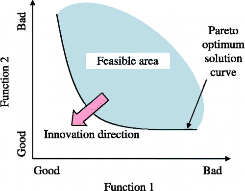
The results of multi-objective optimisation methods are often given as Pareto optimum solution sets. A Pareto optimum solution implies that no improvement in the value of one objective function is possible without a corresponding degradation in the value of the other objective function, which also expresses the trade-off relationship between the evaluated items. An example of a Pareto optimum solution set is shown in Figure . Methods that support the selection of alternative designs that best achieve target values when a design includes restricted constraints and has trade-off relationships are an important subject of research and one such method is trade-off analysis (Kuroiwa Citation2005). In trade-off analysis, alternative designs are compared to examine which design variables and constraints dominate the Pareto optimum solution set, to clarify the relationships between design variables and evaluative items. Such analysis aims to determine optimal design variable values and enable breakthrough solutions by making it easier for design engineers to understand the essence of particular product design problems.
4. Applied example
4.1 Machine tool modelling and design variables
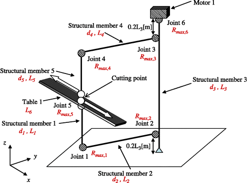
A vertical milling machine is selected as an applied example and its fundamental structure is modelled as shown in Figure , with five beam members, a work table and a motor. The size and weight of these parts are subject to the following assumptions: beam cross-sections are square with d
i
m representing the length of one side and L
i
m () representing the beam length; the table dimensions are width L
6 m, depth 0.5 L
6 m and thickness 0.2 L
6 m; the motor has a fixed mass of 5 kg.
The primary performance characteristic of the machine tool is the machining accuracy and examples of evaluative items influencing this accuracy include the static rigidity, resistance to thermal deformation, durability and response to vibration. The static rigidity is adopted here as the most important evaluative characteristic and the product performance is evaluated using the static compliance F
s, the inverse of static rigidity, i.e. the displacement in the x direction of the cutting point divided by the cutting force in the case where two parallel but opposite forces along the x-axis are applied at the upper and lower sides of the cutting point, as shown in Figure . Here, the direction of the force applied is assumed to be along the x-axis because the stiffness in the x direction has the smallest value, when compared with the values along the y- and z-axes in the model shown in Figure . The lifecycle cost C
total and the environmental impact value EI
total are also used as evaluative items in addition to the product performance F
s. The stages considered for the product's lifecycle in this example are manufacturing, use, disposal and recycling. The design variables used in the optimisation analysis are the side length d
i
of square cross-section members, the maximum value of the contact surface roughness R
max, j
[m] in joints between two adjacent members, the longitudinal length L
i
of members and the material used for the members. The respective design variable constraints for length d
i
and surface roughness R
max,j
are and
. The normal boundary intersection (NBI) method that is a highly efficient algorithm for solving nonlinear multi-objective optimisation problems, a function available in the commercial Optimus software package, is used in the optimisation analysis (Das and Dennis Citation1998). However, since the NBI method cannot handle discrete variables, these are handled as design parameters in the following analyses.
4.2 Formulation of static compliance
Static compliance F s is affected by two design aspects, one pertaining to the beam members and the other pertaining to the joints responsible for the integrity of the assembled machine structure. The deformation at the cutting point δ1 for the assembled members when an external force P (N) is applied at the cutting point can be determined by using a representation based on Castigliano's theorem, as expressed in the following equation. Here, U 1 is the strain energy of members, and E and G are respectively Young's modulus and the modulus of transverse elasticity for the material used to construct the members, and I i is the moment of inertia for the cross-sectional area of member i.
Additionally, the deformation at the cutting point δ2 is determined according to the structure of the joined parts, again using a representation based on Castigliano's theorem but this time in combination with Kragelskii's contact theory (Kragelskii Citation1965) as follows:
Here, U 2 is the strain energy of the joint contact surface, and K j and K′ j are respectively the values of equivalent axial and circumferential rigidity for joint contact area j of the members, obtained via Kragelskii's contact theory. Consequently, the static compliance, defined as the deformation caused by a unit force of 1 (N), is represented as the following equation.
4.3 Formulation of lifecycle costs
The total lifecycle cost C total is expressed as the sum of the manufacturing cost C manufacture, usage cost C use, disposal cost C disposal and recycling cost C recycle as follows:
The manufacturing cost is assumed to be the sum of the material cost C M and machining cost C J.
The material cost C M is calculated by multiplying the total mass M of the milling machine's component members by the unit mass cost c of the material used and is expressed as follows:
The machining cost C J is the cost of machining the contact surfaces of the joints used to connect adjacent component members together in the assembled milling machine. In this example, the relationship between the surface roughness (maximum height type) R max of the joint contact surface and the machining cost per unit area U u yen/m2 is expressed in the following equation, based on cost data for representative surface machining processes.
Next, the usage cost C use is assumed to be simply the cost of electric power C E required to operate the machine. That is,
To calculate the electric consumption P, the cross-sectional dimensions of the milling machine members, the size of the milling machine and the density of the material used in its construction are substituted in the electricity consumption estimation formula proposed by Narita et al. (Citation2005). In this analysis, the considered masses that move are the mass of work table moving along the x-axis, the mass of work table and the mass of member 1 moving along the y-axis, and the mass of member 5 moving along the z-axis. The electric utility rate C e is assumed to be 10 yen/kW h.
The cost of the disposal stage C disposal is calculated based on the abandoned mass M dis, and a given coefficient of disposal per unit mass of the material C dis as follows:
Although the recycling of abandoned machines has inherent costs, it is here assumed that the members used in the construction of the milling machine will contain recycled material. We assume that the cost of the recycling stage C recycle is included in the material cost of the manufacturing stage and that the cost of the recycling stage is zero. (Refer to Section 3.6). That is,
4.4 Formulation of environmental impacts
The environmental impacts are calculated based on the Eco-indicator 99 method and the total environmental impact EI total is assumed to be the sum of four environmental impacts pertaining to the manufacturing, usage, disposal and recycling stages, as follows:
The environmental impact of the manufacturing stage EI manufacture is calculated using M new, the mass of new, non-recycled material used to make the machine and a given index for the new material, IND new, as follows:
The environmental impact of the usage stage EI use is calculated using the total electricity consumption P in the usage stage and IND electricity, a coefficient of consumption per unit electric power, 0.027 point/kW h, as follows:
The environmental impact of the disposal stage EI disposal is calculated using the mass of the abandoned material M dis within the total material used for the milling machine and the index of abandoned material, IND dis, a coefficient of disposal per unit mass of material, as follows:
The environmental impact of the recycling stage EI recycle is calculated using the mass of recycled material M rec within the total material used for the milling machine and the index of recycled material, IND rec, a coefficient of recycling per unit mass of material.
All of the above descriptions are intended as generalised expressions. In the highly simplified example provided here, the mass of the material which is either disposed or recycled is the same as the total mass M of the milling machine's component members represented in Equation (Equation9) in Section 4.3. M
dis is zero when the material is entirely recycled and analogously, M
rec is zero and M
dis is equal to the mass M when all the material is disposed and none is recycled. The case studies explained in Section 5.2.1, in which the machine's material is steel, cast iron or aluminium alloy have the material entirely recycled, while in the case where alumina ceramic is employed, all the material is disposed.
4.5 Machining assumptions
The relative advantages of the optimal design solutions provided by the proposed method vary depending on the sizes of workpieces machined, though for the calculation of electric power cost, machining operations are assumed to be continued for 10 years in the same pattern. To examine the impact that workpiece size has on the design results, three workpiece sizes, S, M and L are chosen as shown in Table . All workpieces are made of cast iron, have similar square cross-sections and the ratio of the x, y and z dimensions are 1:2:3 as shown in Table . Also shown in the table are the radii R of the end mills used, which vary according to the workpiece size.
Table 1 Work piece and tool sizes.
4.6 Discrete design variables
Although the cross-sectional side length of the milling machine's structural members is assumed to be a continuous design variable in this example, the material used for the members and their longitudinal lengths are assumed to be discrete design variables. Four kinds of materials are considered and Table shows the values of their characteristics, namely, density ρ, Young's modulus E, modulus of transverse elasticity G, material unit price c and disposal unit cost c dis. Table also shows Eco-indicator 99 indices for the various environmental impacts. Steel, cast iron and the aluminium alloy are assumed to have perfect recyclability, so no new material is required to produce the milling machine members using these materials. On the other hand, the alumina ceramic cannot be recycled at all, so machine members require a completely new material. Although alumina ceramics are not used to make large machine tool structures, this material is included as a representative high-performance material that offers comparatively lower density and higher stiffness, non-recyclability and a higher material unit price.
Table 2 Material properties and data related to the cost and environmental impact.
Because the optimal lengths of members L i ultimately depend on the size of workpiece to be machined, the assumed values for L i and the cross-section side lengths d i for three different sizes of milling machine (S, M and L) that appropriately match three different workpiece sizes (S, M and L) are as shown in Table .
Table 3 Structural sizes and design variable range.
5. Results and discussion
5.1 Advantages of the proposed design method
Although the original problem includes three objective functions, i.e. static compliance, lifecycle cost and environmental impact, only the static compliance and lifecycle cost are used here in a two-objective optimisation procedure, to streamline the trade-off analysis. This is because the lifecycle cost does not conflict with the environmental impact since the environmental impact of the usage stage, which is based on the consumption of electricity, is much larger than the environmental impact of the other stages and the usage cost is proportional to the total environmental impact. The environmental impacts are evaluated after optimising the above two-objective optimisation problem. First, we compare the results obtained using the proposed design method that considers the product's lifecycle cost with a conventional optimal design method that only considers the manufacturing cost. For the conventional method, the objective functions of the multi-objective optimisation analysis are the manufacturing cost and static compliance, whereas for the proposed method they are the lifecycle cost and the static compliance.
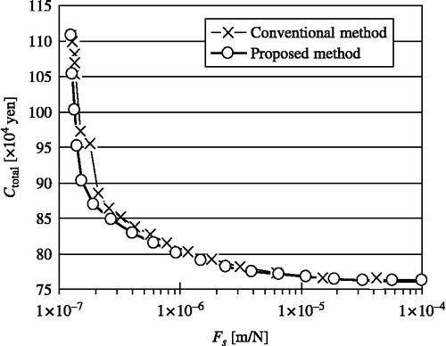
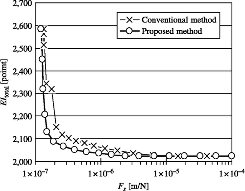
Based on these assumptions, Pareto optimum solutions were obtained for cases using the proposed method and the conventional method. The Pareto optimum solution sets pertaining to the static compliance and total lifecycle cost are shown in Figure , and the Pareto optimum solution sets pertaining to the static compliance and total environmental impact are shown in Figure . The material used to obtain these results is steel and the structural size of the machine and the workpiece size are both S. Concerning the total lifecycle cost C total of the conventional method in Figure , this cost is the sum of the manufacturing cost (obtained as an optimum solution) and the usage cost calculated using the values of design variables in Pareto optimum solutions. On the other hand, concerning the total environmental impact EI total of the conventional method solution illustrated in Figure , this value is the sum of the environmental impact of the usage stage and the environmental impact of the recycling stage calculated using the values of design variables in Pareto optimum solutions, the same as in Figure .
These results show how more preferable solutions can be obtained using the proposed method than with the conventional method, when lifecycle cost and environmental impact are considered simultaneously. To precisely examine differences in the Pareto optimum solutions, each cost and environmental impact over the lifecycle stages and the values of design variables d 4 and d 5 when the value of the static compliance is equal to 1 × 10− 6 m/N are all shown in Table . We selected 1 × 10− 6 m/N as the value for the static compliance because this value lies near the centre of the Pareto optimum solution set plots shown in Figures and .
Table 4 Lifecycle cost, environmental impact and design variables for conventional and proposed methods.
Concerning the lifecycle cost, the proposed method, aiming to minimise the total lifecycle cost, yields a more preferable usage cost C use, whereas the conventional method yields a lower manufacturing cost C manufacture since that is its goal. On the other hand, concerning environmental impact, the environmental impact during the usage stage EI use is approximately 500 times larger than that during the recycling stage EI recycle, as shown in Table . The proposed method provides an environmental impact during the usage stage EI use that is smaller than that provided by the conventional method, but the latter, aiming to minimise the mass of recycled material, provides better results for the recycling stage. That is to say, it is clear that the usage stage greatly influences both the lifecycle cost and the environmental impact in this model.
Next, concerning the cross-section side length of the beam members, design variable d, the proposed method obtains a smaller side length d 5 for moving member 5 than that of the conventional method, but the side length d 4 of fixed member 4 is correspondingly larger. This is because the member that moves must be made lighter to reduce the cost of electric power consumed and the fixed member becomes heavier in compensation, to maintain an appropriate value for the static compliance of the entire structure.
5.2 Improving Pareto optimum solutions by manipulating discrete design variables
In this applied example, the cross-sectional side length of beam members is dealt with a continuous design variable but the material used to construct the members and the overall size of the machine tool are discrete design variables. Below, we examine differences in the Pareto optimum solutions that result from using different values for these discrete design variables.
5.2.1 Changes in material
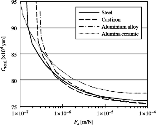
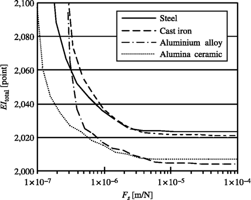
The Pareto optimum solution sets pertaining to the static compliance and total lifecycle cost, and the static compliance and total environmental impact are respectively shown in Figures and , when machining is performed by machine tools constructed from the four given materials. In this case, the size of the machine structure and the workpiece are both S, as represented in Tables and .
Considering the lifecycle cost, the optimal material for constructing the milling machine depends on the selected value of the static compliance, as shown in Figure . For instance, when the static compliance value is 1 × 10− 6 m/N, reduced total lifecycle costs are seen for the materials in the sequence of cast iron, steel, aluminium alloy and alumina ceramic. On the other hand, in Figure , where environmental impact is considered, the same value for the static compliance yields a material sequence from best to worst of alumina ceramic, aluminium alloy, steel and cast iron. Values for lifecycle costs and environmental impacts for all lifecycle stages and the four materials when the value of the static compliance is 1 × 10− 6 m/N are shown in Table .
Table 5 Lifecycle cost and environmental impact for the four materials.
Viewing Table , we see that cast iron offers the lowest manufacturing cost, with steel, aluminium alloy and alumina ceramic in order of increasing cost, similar to the order for the four materials seen when considering lifecycle cost, due to the impact of material cost. On the other hand, as shown in Table , materials with lower density provide lower usage cost, but differences in the manufacturing cost among the four materials are larger than those in the usage cost. This is because the machining conditions (e.g. feed rate and cutter rpm) are major factors in the usage cost while the physical characteristics of the material are minor. The order of the materials from best to worst is the same for both the total lifecycle cost including the usage cost and the manufacturing cost. However, the range of manufacturing costs for the four materials is larger than that of the total lifecycle costs, so it is likely that differences in the usage costs will have a greater effect on the total lifecycle cost as the structure of the machine, machining conditions and material characteristics are varied.
Although the material density, Young's modulus and modulus of transverse elasticity were selected as the material characteristics, since static compliance was the evaluative characteristic for the product performance here, there are a number of other evaluative items appropriate for machine tools, such as durability, resistance to thermal deformation and so on. To evaluate such items, additional material characteristics such as tensile strength, thermal conductivity and the coefficient of thermal expansion would have to be considered.
Considering the sum of the environmental impact values during the manufacturing and recycling stages (), which are affected by the mass of the materials used to construct the milling machine, the alumina ceramic provides the best, i.e. smallest, value among the four materials, as shown in Table . Because the alumina ceramic is not recycled, the value of EI
recycle is zero, and the value of EI
manufacture is small owing to its lower density and the low value of IND
new. On the other hand, the aluminium alloy, having the lowest density, shows values in close agreement with those of the higher density steel and cast iron materials, since the environmental impact IND
rec values in the recycling stage are large. Though steel, cast iron and aluminium alloy are assumed to be perfectly recyclable here, their environmental impact increases by factors of 4, 10 and 13, respectively, as shown in the IND
new, IND
rec indices of Table , if newly produced material is used to construct the milling machine. The disposal of alumina ceramic has hardly any effect upon the usage stage, and the environmental impact of the alumina ceramic in the usage stage is smallest of all. This is because the mass of the moving member is less for a given rigidity value, thanks to the lower density and higher stiffness of the ceramic, hence the electricity consumption is reduced. Consequently the total environmental impact of alumina ceramic is the smallest of all materials for the total lifecycle of the machine.
Here, only the mass of material used to construct the milling machine is considered and other factors in the manufacturing stage, such as machining, are not considered with respect to the environmental impact during manufacturing. The environmental impact during manufacturing may become large when the material used is difficult to machine even if the environmental impact of producing it is relatively small. These relationships indicate that materials whose characteristics are all advantageous are not required to achieve improved optimal design solutions. Materials that offer only one or two advantages, say in terms of weight or recyclability, can be the cause of improved optimum solutions.
5.2.2 Changes in milling machine size
When the machine tool size is selected in the designing process, the optimum size of the milling machine will vary depending on the size of workpiece to be machined. If the workpiece size is fixed, an appropriate size of milling machine can be considered optimal, but practical machining scenarios require accommodating a range of workpiece sizes. We therefore consider cases where two or three different sizes of workpieces are machined by the three different sizes of milling machine (S, M and L), data for which appears in Table . Milling machine is assumed to be made of steel. Two combinations of workpiece sizes (hereafter called a task pattern) are set to examine these cases, as shown in Table . One, two or three different sizes of milling machine are used to process the workpieces over a period of 10 years.
Table 6 Milling machine structural size.
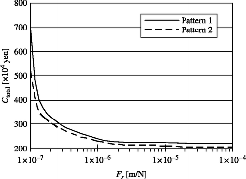
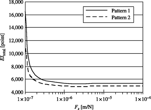
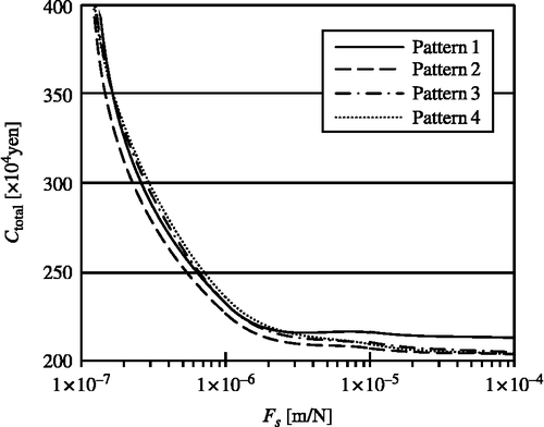
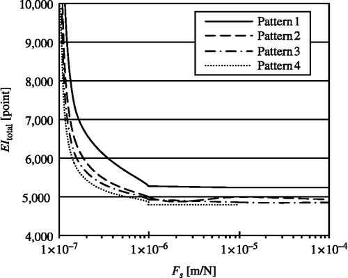
In task pattern (i), S-size workpieces are machined during the first half of the 10-year processing period and L-size workpieces are machined during the remaining five years. For task pattern (ii), S-, M- and L-size workpieces are machined in order for one-third of the 10-year period, each. Table shows candidate combinations concerning the structural sizes of the milling machine and the workpiece task patterns. For task pattern (i), Figure shows the Pareto optimum solution sets pertaining to the static compliance F s and total lifecycle cost C total, and Pareto optimum solution sets for static compliance F s and total environmental impact EI total are shown in Figures and , respectively, for structural size patterns 1 and 2. The figures indicate that structural size pattern 2 is more preferable both in terms of the lifecycle cost and environmental impact.
Table shows values for the various lifecycle costs, environmental impacts and total lifecycle cost for the static compliance value of 1 × 10− 6 m/N in both Figures and . The data in Table indicates that, for the manufacturing cost, pattern 1 is more preferable, whereas pattern 2 is preferable for the usage cost. This is because the manufacturing cost of pattern 1 is smaller because only the L-size machine is constructed, but the usage cost is not minimal because the structural size is not optimal for the entire task pattern. On the other hand, the manufacturing cost for structural size pattern 2 is larger, since two different sizes of milling machine are constructed, but the usage cost is less because optimal structural sizes are available for processing the different sizes of workpiece. Pattern 2 is thus more preferable for task pattern (i) due to the combination of these factors.
Table 7 Lifecycle cost and environmental impact for task pattern (i).
For task pattern (ii), Pareto optimum solution sets for the static compliance F s and total lifecycle cost C total, and for the static compliance F s and total environmental impact EItotal are shown in Figures and , respectively, for the four structural size patterns shown in Table are used.
The optimal structural size pattern pertaining to the lifecycle cost varies depending on the values chosen for the static compliance, due to the complexity of the task pattern. Table shows the lifecycle costs and environmental impacts for a static compliance value of 1 × 10− 6 (m/N) in both Figures and .
Table 8 Lifecycle cost and environmental impact for task pattern (ii).
Concerning task pattern (ii), as seen with pattern (i), the manufacturing cost for structural size patterns that require relatively fewer different sizes of machines is lower, but usage cost increases because the machine sizes are not optimal for the workpieces being processed. Conversely, the manufacturing cost of structural size patterns requiring a greater variety of machine sizes is larger, but usage cost decreases. In any case, for task pattern (ii), the total lifecycle cost is lowest when structural size pattern 2 is used, despite the fact that the manufacturing cost and usage cost are not optimal. That is to say, a structural size pattern which provides optimal values for certain of the lifecycle stages may not be optimal from the view point of total lifecycle cost. Thus, calculation of the total lifecycle cost is required to judge which structural size pattern is optimal for a given task pattern. Concerning the environmental impact, the structural size pattern that yields the lowest value during the usage stage is best for the total lifecycle cost because the value during the usage stage is proportionally much larger than the environmental cost of the other lifecycle stages.
6. Conclusions
For this research, a common machine tool product used for a long period of time was chosen as the design subject and an optimum system design method considering the product lifecycle was proposed. The results obtained in this research are summarised as follows:
-
It was confirmed that the cost advantages offered by an LCD approach when the product's entire lifecycle is considered can be quantitatively evaluated by comparing the design solutions when all lifecycle factors are considered with the solutions provided by a conventional method that only considers the manufacturing stage.
-
We examined a methodology for dealing with complex evaluative items and obtained optimum solutions through the use of a simplified product model. (We chose not to propose a novel optimisation method or technique.) Product designs were evaluated from the viewpoint of environmental impact as well as product performance and lifecycle cost. The proposed method supports decision making by designers while simultaneously evaluating product performance, lifecycle costs and environmental impacts.
-
Examination of the changes in product design Pareto optimum solution sets that occurred in response to changes in the value of discrete design variables revealed promising directions for further improvement of optimum solutions. Focusing on such details can effectively indicate practical directions for research and development that enables significant improvement of various design parameters.
-
It was confirmed that the proposed method provides design solutions where the size of the machine structure is optimal for the intended usage conditions. That is, the proposed method provides optimal combinations of the milling machine size according to given usage conditions of workpiece size, by allowing the comparison of different size combinations. A designer can thus evaluate and select the optimal machine product considering its lifecycle according to analyses that include usage parameters and alternative machine designs.
In our research, here, we focused on an optimal product design in which the overwhelming majority of the cost occurs during the usage stage. To increase the efficacy of the proposed method in practical scenarios, we hope to focus more upon evaluative items such as disassembly and reuse of the product, the reuse of parts, recycling of materials and so on, to achieve optimal designs for products where maintenance costs or, especially, disposal costs assume a larger portion of the total cost, as is often the case for mass-produced goods that are as yet not adequately recycled. In the future, we intend to develop an optimum design method for products that includes lifecycle issues and is able to consider the stages of maintenance and reuse, evaluate part longevities and the costs of reusing a product or its parts, and similar points. We also intend to investigate product models that more accurately reflect real-world examples.
Acknowledgements
We would like to express our profound gratitude to Dr Masao Nakagawa (Senior Engineer, Okuma Corporation) for his advice and kind assistance concerning the references listed in this research.
References
- Alting , L. 1993 . “ Life-cycle design of products: a new opportunity for manufacturing enterprises ” . In Concurrent engineering , 1 – 17 . New York : Wiley . In
- Asiedu , Y. and Gu , P. 1998 . Product life cycle cost analysis: state of the art review . International Journal of Production Research , 36 ( 4 ) : 883 – 908 .
- Bevilacqua , M. 2007 . Development of a sustainable product lifecycle in manufacturing firms: a case study . International Journal of Production Research , 45 ( 18–19 ) : 4073 – 4098 .
- Bras , B. and Emblemsväg , J. 1996 . “ Designing for the life-cycle: activity-based costing and uncertainty ” . In Design for X, concurrent imperatives , 399 – 423 . London : Chapman & Hall . Chap.19
- Cheung , W.M. 2007 . “ A study of life cycle costing in the perspectives of research and commercial application in the 21st century ” . In Proceeding of ASME international design engineering technical conferences , DETC2007-34425 In
- Das , I. and Dennis , J.E. 1998 . Normal boundary intersection: a new method for generating the pareto surface in nonlinear multicriteria optimization problems . Society for Industrial and Applied Mathematics Journal on Optimization , 8 ( 3 ) : 631 – 657 .
- Fragiadakis , M. , Lagaros , N.D. and Papadrakakis , M. 2006 . Performance-based multiobjective optimum design of steel structures considering life-cycle cost . Structural and Multidisciplinary Optimization , 32 ( 1 ) : 1 – 11 .
- Gershenson , J.K. , Prasad , G.J. and Allamneni , S. 1999 . Modular product design: a life-cycle view . Journal of Integrated Design and Process Science , 3 ( 4 ) : 13 – 26 .
- Goedkoop, M. and Spriensma, R., 1999. The Eco-indicator 99: a damage oriented method for life cycle impact assessment. Methodology Report, PRe Consultants
- Inverse Manufacturing Forum Supervision . 2004 . Handbook of inverse manufacturing , Edited by: Kimura , H. Tokyo : Maruzen .
- Itsubo , N. and Motoshita , M. 2005 . Life cycle assessment (LCA)(III-3): outline and current research issues of LCIA methodology LIME . Journal of the Japan Institute of Energy , 84 ( 10 ) : 872 – 878 .
- Kato , S. 2001 . Life cycle assessment estimation for eco-management of co-generation systems . Journal of Energy Resources Technology , 123 ( 1 ) : 15 – 20 .
- Kitagawa , M. and Yamamoto , R. , eds. 2005 . “ Science on sustainability 2006 ” . In Research on the scientific basis for sustainability , 215 – 238 . Tokyo : E-Square Inc .
- Kobayashi , H. 2004 . Life cycle design support in manufacturing company . Journal of Society of Instrument and Control Engineers , 43 ( 5 ) : 425 – 428 .
- Kragelskii , I.V. 1965 . Friction and wear , London : Butterworths .
- Kuroiwa , T. 2005 . Trade-off analysis method . Toshiba Review , 60 ( 1 ) : 48 – 51 .
- Masui , K. 2000 . QFD for product design based on life-cycle strategy . Journal of the Japan Society for Precision Engineering , 66 ( 4 ) : 567 – 571 .
- Narita , H. 2005 . Development of prediction system of environmental buraden for machine tool operation (1st report, proposal of calculation method of environmental burden) . Transactions of the Japan Society of Mechanical Engineers, Series C , 71 ( 704 ) : 1392 – 1399 .
- Newcomb , P.J. , Bras , B. and Rosen , D.W. 1998 . Implications of modularity on product design for the life cycle . Journal of Mechanical Design , 120 : 483 – 490 .
- Ogushi , Y. , Kandlikar , M. and Dowlatabadi , H. 2006 . “ Assessing product life cycle strategies in the Japanese market ” . In Innovation in life cycle engineering and sustainable development , Edited by: Brissaud , D. , Brissaud , D. and Brissaud , D. 49 – 64 . Berlin : Springer .
- Sandberg , M. , Boart , P. and Larsson , T. 2005 . Functional product life-cycle simulation model for cost estimation in conceptual design of jet engine components . Concurrent Engineering: Research and Applications , 13 ( 4 ) : 331 – 342 .
- Seo , K.-K. 2002 . Approximate estimation of the product life cycle cost using artificial neural networks in conceptual design . International Journal of Advanced Manufacturing Technology , 19 : 461 – 471 .
- Steen , B. 1999 . “ A systematic approach to environmental priority strategies in product development (EPS). Version 2000 ” . In Center for environmental assessment of products and material systems , Gotheburg, Sweden : Technical Environmental Planning, Chalmers University of Technology . In
- Takai , S. 2006 . “ A lifecycle-cost model of concept testing ” . In Proceeding of ASME international design engineering technical conferences , DETC2006-99605 In
- Takata , S. , Umeda , Y. and Kato , S. 2000 . Roadmap for life cycle design . Journal of the Japan Society for Precision Engineering , 66 ( 12 ) : 1853 – 1857 .
- Yoshimura , M. 2007 . System design optimization for product manufacturing , 37 Tokyo : Yokendo . (in Japanese)
