Abstract
In order to enable the manufacture of lightweight materials for transportation equipment, such as cars and aircraft, an improvement in the fatigue strength of materials is required, as these forms of transport are designed taking fatigue fracture into consideration. Surface treatment procedures, such as shot peening, are generally employed to improve fatigue strength. Shot peening deforms metallic materials to produce work hardening and introduce compressive residual stress, leading to improved fatigue strength. Although shot peening is an effective and reliable method against fatigue fracture, the shot eventually becomes dust and industrial waste. Recently, a peening method without the use of shot using cavitation impact has been developed. This is called ‘cavitation peening’. In the present paper, gears, which are typical machine components, were examined in order to demonstrate the improvement in fatigue strength by cavitation peening. Gears made of carburised chromium molybdenum steel were treated by cavitation peening and shot peening. The fatigue strength was evaluated using a power circulating-type gear test machine. Under the conditions employed, the gear lifetime was limited by fracture at the root of the tooth. The improvement in the fatigue strength of gears treated by cavitation peening was 24% and in those treated by shot peening it was 12% compared with non-peened gears. It was demonstrated that cavitation peening can improve the fatigue strength of gears without the use of shot.
Introduction
The manufacture of lightweight transport equipment is one of the strategies being employed to realise a sustainable society, as it reduces CO2 emissions and is also good from the point of view of petroleum resources. The size, i.e. the weight, of the metallic machine components of cars and aircraft is mainly determined by their fatigue strength. Surface modification techniques for improving fatigue life will lead to reduced material and energy consumption since it will lead to less frequent replacement of components. Consequently, there will be a reduction in new material extraction, processing, transport and eventual landfill. Shot peening is one of the effective surface modification processes used to improve fatigue strength and reliability. The impact of shot on the defects that are the source of fatigue fracture produces work hardening and introduces compressive residual stress (Al-Obaid Citation1990). However, the use of shot produces dust that is not only harmful to workers but also presents the danger of dust explosion. In addition, the broken shot eventually becomes industrial waste. Another disadvantage of shot peening is that the impact of shot causes an increase in surface roughness, which reduces the fatigue strength. If a peening method without the use of shot was to be established, it would support the development of lightweight materials for transport equipment, as the smooth surface would help improve the fatigue strength of the metallic machine components.
A peening method using cavitation impact, which normally causes severe erosion in hydraulic machinery, such as pumps and valves (Soyama et al. Citation1992, Brennen Citation1995), has been proposed. It is called ‘cavitation peening’ (Soyama Citation2006) or ‘cavitation shotless peening’ (Soyama et al. Citation2002, Citation2003a, Odhiambo and Soyama Citation2003) as shot is not required. The introduction of compressive residual stress using a cavitation tunnel (Blickwedel et al. Citation1987) and ultrasonic cavitation (Rawers et al. Citation1991) has been reported. In both cases, the cavitating area was limited. Thus, the treatment area was also limited and therefore these methods cannot be utilised for the surface modification of machine components. The introduction of compressive residual stress using a cavitating jet, i.e. a high-speed submerged water jet with cavitation bubbles, was proposed (Soyama et al. Citation1996a) and its efficacy was confirmed (Hirano et al. Citation1996). In the case of the cavitating jet, the cavitation bubbles can be produced wherever the impact is required and the intensity can be controlled by hydraulic parameters such as the upstream and downstream pressures at the nozzle (Soyama et al. Citation1998). A normal water jet, i.e. a water jet in air, can introduce compressive residual stress (Tönshoff et al. Citation1995). However, by using a cavitating jet for modifying the surface, the following advantages can be obtained: the impact pressure generated by the cavitating jet can be higher than that from a water jet in air at the same pump pressure and the treatment area with a cavitating jet can be much greater than that for a water jet in air (Yamauchi et al. Citation1995). Although a conventional cavitating jet has been produced by injecting a high-speed water jet into a water-filled chamber, a cavitating jet in air has to make do without the chamber. In this case, by injecting a high-speed water jet into a low-speed water jet, a cavitating jet in air for peening was successfully realised (Soyama Citation2004). The optimised cavitating jet in air was found to be more effective for peening than a normal cavitating jet in water (Soyama Citation2004), and the improvement in the fatigue strength of stainless steel treated by a cavitating jet in air was demonstrated using a plate bending fatigue test (Soyama Citation2007). As compressive residual stress is introduced by cavitation peening, it has been applied as preventive maintenance against stress corrosion cracking in nuclear power plants (Saitou et al. Citation2003). Laser peening has also been applied to nuclear power plants (Sano et al. Citation2008) and furthermore, it has been proposed for application to machine components. However, the cost of laser peening is nearly 10 times higher than that of conventional shot peening due to the expensive laser system. In the case of cavitation peening, an expensive plunger pump is not required as cavitation impact is used and high pressure is not required. The cost of cavitation peening is similar to or less than that of shot peening, as shot is not used. Cavitation peening can enhance the fatigue strength of metallic materials in the same way as shot peening. Although the improvement in fatigue strength of metallic materials treated by cavitation peening has been demonstrated using a rotating-bending fatigue test (Soyama et al. Citation2001, Citation2002) and a plate bending fatigue test (Soyama Citation2007), a real machine test is required.
Typical machine components requiring shot peening are gears. As shot peening roughens the surface, barrel polishing is subsequently required. The great advantage of cavitation peening is that the treated surface is very smooth compared with that after shot peening (Soyama et al. Citation2004). If the fatigue strength of gears can be enhanced by cavitation peening, this would be a powerful surface treatment method for them, considering the tribological problems related to the contacting surfaces. The strength or the lifetime of gears is determined by two damage patterns, i.e. fatigue fracture at the roots of the teeth and pitting damage on the tooth surface. If the fatigue strength and applied pressure of gears can be improved, lightweight gears can be realised. In a previous paper, the pitting damage on gears and rollers was reduced by cavitation peening (Seki et al. Citation2008). It has also been proven that cavitation peening improves the fatigue strength of gears evaluated by a bending fatigue test (Soyama and Macodiyo Citation2005). In the previous experiment, the gear under test was fixed, and with an applied load the gear fractured at the roots of the teeth. Although it was possible to enhance the fatigue strength of the gear under fixed conditions by cavitation peening, the fatigue strength should be examined using a power circulating-type gear test machine, in which the gear under test is rotated while the load is applied.
In the present paper, in order to demonstrate the effect of peening by cavitation impact without shot on an actual machine component, the fatigue strength of the gear was evaluated using a power circulating-type gear test machine. The gear was treated by cavitation peening and shot peening. This is the first report to demonstrate the improvement in fatigue strength of a gear treated by cavitation peening using a power circulating-type gear test machine and to compare it to one treated by shot peening.
Principle of cavitation peening
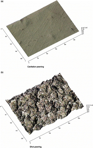
Cavitation is a phase change phenomenon, which means the water vaporises due to a decrease in pressure by increasing the flow velocity. Although much research has been done on spherical bubbles (Brennen Citation1995), longitudinal cavitation, which consists of tiny longitudinal cavitation bubbles, as shown in Figure , causes severe cavitation impact (Soyama et al. Citation1994). This means that longitudinal cavitation can be useful for cavitation impact applications. A schematic diagram of the development and collapse of longitudinal cavitation is shown in Figure . In the low-pressure region of the vortex core induced by an increase in flow velocity, cavitation nuclei, which are tiny bubbles desorbed in water, become cavitation bubbles. These are arranged longitudinally due to the vortex. When the flow velocity is decreased, the bubbles shrink and a micro jet is generated. The micro jet causes severe cavitation impact which can deform metallic materials. As the cavitation bubbles rebound in a short time, a shock wave is produced causing plastic deformation of the metallic material. These micro jets and shock waves can be used for peening in place of shot peening. In the case of cavitation peening, the surface is smooth compared with a shot-peened one, as there is no collision between solid materials. In order to demonstrate the difference in surface roughness induced by cavitation peening and shot peening, surfaces observed by a laser scanning microscope are shown in Figure . In this case, the treated material was tool alloy steel. Although plastic deformation pits induced by cavitation impact can be seen, the surface is smoother than that produced by shot peening. In addition, the arithmetic average roughness of the non-peened specimen, the shot-peened specimen and the cavitation-peened specimen made of tool alloy steel are 0.06, 1.00 and 0.18 μm, respectively (Soyama et al. Citation2003b). In the case of shot peening, the metallic material was peened by the impact between solid materials, whereas in the case of cavitation peening the material was peened by collapsing cavitation bubbles. Therefore, the increase in surface roughness of the specimen treated by cavitation peening is smaller than that by shot peening. The introduced residual stress of both cavitation peening and shot peening was about − 800 MPa (Soyama Citation2004). This means that cavitation peening can introduce compressive residual stress without an increase in surface roughness. Cavitation peening can also decrease micro-strain, which might be a source of fatigue fracture (Soyama and Yamada Citation2008).
Figure 1 Severe erosive longitudinal cavitation.
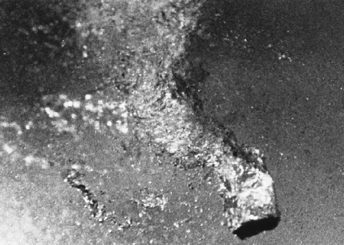
Figure 2 Schematic diagram of the development and collapse of longitudinal cavitation.
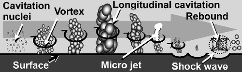
Figure 3 Aspect of peened surface: (a) cavitation peening and (b) shot peening.
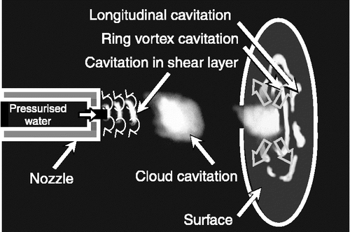
In the case of cavitation peening, cavitation bubbles are generated by injecting a high-speed water jet into water. This is called a cavitating jet. A schematic diagram of high-speed observation of a cavitating jet is shown in Figure (Soyama et al. Citation1995, Citation1996b). When pressurised water is injected into water, cavitation bubbles form in the low-pressure region of the vortex core in the shear layer around the jet. These vortex cavitations combine and become a cloud cavitation consisting of tiny bubbles. When the cloud cavitation impinges on the surface, it becomes a ring vortex cavitation. A part of the ring vortex cavitation collapses giving rise to longitudinal cavitation. The cloud cavitation was shedding periodically with a frequency of several kilohertz (Soyama et al. Citation1995). This means that a cavitating jet frequently produces longitudinal cavitation.
Figure 4 Schematic diagram of cavitating jet.
Experimental facilities and procedure
Figure illustrates the cavitating jet apparatus used for cavitation peening in the present experiment. The test chamber, where the test or mating gears were set, was filled with tap water and then a high-speed water jet, pressurised by a plunger pump, was injected through a nozzle into the chamber. Details of the apparatus can be found in the following references (Soyama et al. Citation2002, Citation2008, Soyama and Macodiyo Citation2005, Seki et al. Citation2008). Considering the results of previous work, the injection pressure p 1 and the pressure of the chamber p 2 were selected to be 30 and 0.42 MPa, respectively. In the present article, the pressures given are the absolute pressures. The throat size of the nozzle used was 2 mm in diameter. The stand-off distance is defined as the distance from the upstream corner of the nozzle throat to the surface at the root of the gear tooth. This was set at 80 mm. These conditions for cavitation peening were optimised in a previous report (Soyama Citation1998). Both the test and mating gears were treated by cavitation peening for 5 min, rotating at a constant speed of 20 rpm.
Figure 5 Cavitating jet apparatus for cavitation peening.
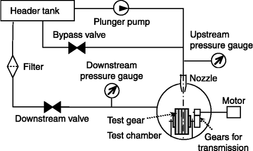
Table describes the properties of the test and mating gears, which are spur gears with teeth with involute profiles and a module of 2.4 mm. Both the test and mating gears are made of chromium molybdenum steel, approved by Japanese Industrial Standard JIS SCM420H, and were finish ground after carburising. The gears were treated by cavitation peening or shot peening. A non-peened gear, labelled the NP gear, was prepared for comparison. This was finished by barrel polishing to make the gear teeth to be the same shape and for them to engage in the same fashion as the other specimens. The shot peening conditions were as follows: the injection pressure of the shot was 0.2–0.3 MPa and the diameter and Vickers hardness of the shot were 0.3 mm and 700, respectively. After shot peening, the gears were finished by barrel polishing in the same way as the NP gear. In the case of cavitation peening, the gears were treated by cavitation peening after barrel polishing, as the surface treated after cavitation peening was very smooth compared with the shot-peened surface.
Table 1 Properties of the gears.
In this study, a power circulating-type gear test machine was used. The test gear was set to be the driving gear, the mating gear was set to be the driven one and the driving speed for the fatigue test was 2600 rpm. In the present study, the torque D n was used to refer to the loading on the surface of the gear tooth, and the number of cycles N to fracture was measured. The D n –N curve was determined. The temperature of the lubricant was controlled to be 353 ± 2 K and pressure lubrication was implemented.
Experimental results
Figure illustrates a pure aluminium surface that has been exposed to a cavitating jet for 1 min using the present conditions in order to show the area treated. The erosion pattern is typical of that induced by a cavitating jet. The erosion at the centre of the jet is only slight and the main erosion region is an annular ring with an outer diameter of about 33 mm and an inner diameter of about 17 mm. Cavitation clouds around the jet hit the surface, spread out and then collapse as shown in Figure . As the impact is produced as the bubble collapses, the main erosion region, i.e. the peened area, has an annular shape. Since the width of the teeth of the test and mating gears was 7 and 10 mm, respectively, the cavitation bubbles cannot develop sufficiently on the surface of the gear teeth. Therefore, the test and mating gears were each stacked with three other dummy gears of the same type, as shown in Figure . For reference, a 25 mm diameter dotted circle is shown in Figures and . The test or mating gear for the fatigue test was set at position No. 1 and the centre of the jet was set to the centre of the dummy gear at position No. 3.
Figure 6 Appearance of eroded pure aluminium surface induced by a cavitating jet.
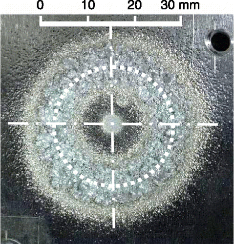
Figure 7 Set-up of test gear with dummy gears for cavitation peening.
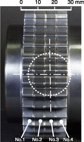
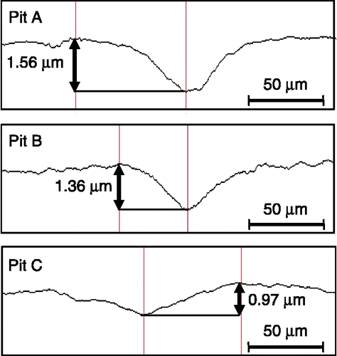
Figure shows a surface treated by cavitation peening observed using a laser microscope. Several pits have appeared on the surface. As the surface has not been eroded, these pits are plastic deformation pits without mass loss. The diameters of the pits are from a few tens of micrometre to about 100 μm. Three typical pits, i.e. pits A–C in Figure , were measured individually using the laser microscope, and the profiles of these are shown in Figure . The depths of pits A–C are 1.56, 1.36 and 0.97 μm, respectively. That is, the plastic deformation pits induced by cavitation impact are narrow. In the case of shot peening, the shape of the pit is generally hemispherical because small balls are generally used for shot. The pressure distribution between the shot and the surface is a half-elliptic pressure distribution because of Hertz contact (Al-Obaid Citation1990). On the other hand, Soyama reported that the pressure distribution of an individual cavitation impact is cone shaped with a maximum intensity at the cone centre (Soyama and Saito Citation2003). These pressure distributions can affect the shape of pits after peening techniques.
Figure 8 Emergence of pits on the tooth surface induced by cavitation impacts.
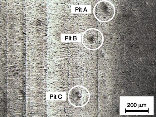
Figure 9 Profiles of pits induced by cavitation peening.
Figures and show the fractured NP gear and the fractured cavitation-peened gear, respectively. In these figures, an overview of the fractured tooth, placed back on the gear after breaking, is shown in (a), and the origins of the break are indicated by arrows. The surface of the gear tooth is shown in (b), and the limits of the contact area are indicated by arrows. Both with and without peening, the gear tooth broke at the dedendum circle and the fracture was initiated at the surface. Although the contact area is shown by the shiny line as seen in Figures (b) and (b), pitting damage was not observed. Under the present conditions, the gear was fractured at the root of the tooth.
Figure 10 Fractured NP gear. (a) The arrow shows the origin of the break. (b) The arrow shows the limits of the contact area.
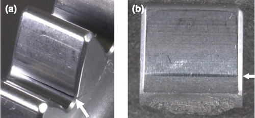
Figure 11 Fractured gear treated by cavitation peening. (a) The arrow shows the origin of the break. (b) The arrow shows the limits of the contact area.
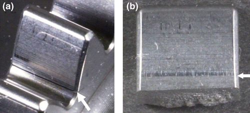
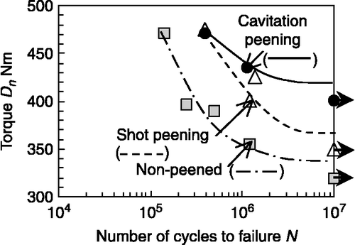
Figure shows the D n –N curve obtained using the power circulating-type gear test machine. The fatigue torque at 107 cycles was determined by Little's method (Little Citation1972), which showed it to be 337 Nm for the NP gear, 376 Nm for the shot-peened gear and 418 Nm for the caritation peened gear. Incidentally, Little's method is used for calculating the fatigue strength using small sample fatigue-limit response data. The fatigue torque of the test gear treated by shot peening was increased by 12% and that of the gear treated by cavitation peening was increased by 24% compared with that of the NP gear. Under the present test conditions, it is clear that the improvement in fatigue strength of the test gear treated by cavitation peening is greater than that treated by shot peening. Considering the material mechanics, the maximum bending stress occurs at the dedendum circle of the gear, and the gears are fractured at the dedendum circle as shown in Figures and . However, the introduction of compressive residual stress and the hardness at the dedendum circle of the gear can have an effect on improving the fatigue strength after cavitation peening. In a previous paper, it was reported that a compressive residual stress of approximately 200 MPa was introduced into the dedendum circle of the gear, and the gear was work hardened after cavitation peening (Seki et al. Citation2008). In the case of cavitation peening, the cavitation bubble flows into the dedendum circle more easily than the shot in shot peening. In addition, the increase in surface roughness after cavitation peening is smaller than that after shot peening, the fatigue crack initiation life of cavitation-peened specimen is longer than that of non-peened specimen (Masaki et al. Citation2008), and the micro-strain, which is caused by adjacent grains and random strain in grains, is reduced by cavitation peening (Soyama and Yamada Citation2008). Thus, the fatigue strength after cavitation peening is greater than that after shot peening.
Figure 12 Improvement in the fatigue strength of the test gear by cavitation peening.
Conclusions
In this study, a shot-free surface modification method was proposed for the improvement of fatigue strength in metallic materials to enable lightweight transport equipment to be developed in a more sustainable way. Although shot peening is an effective way of improving the fatigue strength of metallic machine components, unfortunately, shot produces industrial waste and the danger of dust explosion. A peening method without shot using the cavitation impact induced by a cavitation bubble collapsing is called ‘cavitation peening’.
In order to demonstrate the improvement in the fatigue strength of gears by cavitation peening, gears treated by cavitation peening and shot peening were investigated using a power circulating-type gear tester. Under the conditions used here, the improvement in the fatigue torque of a test gear treated by shot peening was 12% compared with that of a nNP gear, while that of a gear treated by cavitation peening was 24%. Thus, the fatigue strength of gears treated by cavitation peening was increased, with double the improvement gained by shot peening. It can be concluded that cavitation peening is a more effective surface modification method than shot peening.
Acknowledgements
This work was partly supported by the Japan Society for the Promotion of Science under Grant-in-Aid for Scientific Research (A) 20246030. The power circulating-type gear test was carried out at Honda R&D Co., Ltd., working cooperatively with Mr Takashi Tanaka. The authors express their appreciation to both.
References
- Al-Obaid , Y.F. 1990 . A rudimentary analysis of improving fatigue life of metals by shot-peening . Journal of Applied Mechanics, Transactions of the ASME , 57 ( 2 ) : 307 – 312 .
- Blickwedel , H. 1987 . “ Modification of material structure by cavitation and liquid impact and their influence on mechanical properties ” . In 7th International conference on Erosion by Liquid and Solid Impact Edited by: Fields , J.E. and Dear , J.P. 31 – 36 . 7–10 September, Cambridge
- Brennen , C.E. 1995 . Cavitation and bubble dynamics , New York, NY : Oxford University Press .
- Hirano , K. 1996 . Effects of water jet peening on corrosion resistance and fatigue strength of type 304 stainless steel (in Japanese) . Journal of the Society of Materials Science, Japan , 45 ( 7 ) : 740 – 745 .
- Little , R.E. 1972 . Estimating the median fatigue limit for very small up-and-down quantal response tests and for S-N data with runouts . ASTM STP , 511 : 29 – 42 .
- Masaki , K. , Ochi , Y. and Soyama , H. 2008 . “ Fatigue property improvement of type 316L steel by cavitation shotless peening ” . In 10th International conference on Shot Peening Edited by: Tosha , K. 105 – 110 . 15–18 September, Tokyo
- Odhiambo , D. and Soyama , H. 2003 . Cavitation shotless peening for improvement of fatigue strength of carbonized steel . International Journal of Fatigue , 25 ( 9–11 ) : 1217 – 1222 .
- Rawers , J.C. , McCune , R.A. and Dunning , J.S. 1991 . Ultrasound treatment of centrifugally atomized 316 stainless steel powders . Metallurgical Transactions A , 22 ( 12 ) : 3025 – 3033 .
- Saitou , N. 2003 . Development of water jet peening technique for reactor internal components of nuclear power plant . Journal of Jet Flow Engineering (in Japanese) , 20 ( 1 ) : 4 – 12 .
- Sano , Y. 2008 . “ Laser peening without coating: process, effects and applications ” . In 10th International conference on Shot Peening Edited by: Tosha , K. 423 – 428 . 15–18 September, Tokyo
- Seki , M. 2008 . Rolling contact fatigue life of cavitation-peened steel gear . Tribology Online , 3 ( 2 ) : 116 – 121 .
- Soyama , H. 1998 . Material testing and surface modification by using cavitating jet . Journal of the Society of Materials Science, Japan , 47 ( 4 ) : 381 – 387 .
- Soyama , H. 2004 . Introduction of compressive residual stress using a cavitating jet in air . Journal of Engineering Materials and Technology, Transactions of the ASME , 126 ( 1 ) : 123 – 128 .
- Soyama , H. 2006 . Surface modification of metallic materials by cavitation peening (in Japanese) . Materia Japan , 45 ( 9 ) : 657 – 663 .
- Soyama , H. 2007 . Improvement of fatigue strength by using cavitating jets in air and water . Journal of Materials Science , 42 ( 16 ) : 6638 – 6641 .
- Soyama , H. and Macodiyo , D.O. 2005 . Fatigue strength improvement of gears using cavitation shotless peening . Tribology Letters , 18 ( 2 ) : 181 – 184 .
- Soyama , H. and Saito , K. 2003 . “ Relationship on cavitation shotless peening between residual stress and pressure distribution of cavitation impact (in Japanese) ” . In The mechanical engineering congress, 2003 Japan (VI) 145 – 146 . 5–8 August, Tokushima
- Soyama , H. and Yamada , N. 2008 . Relieving micro-strain by introducing macro-strain in a polycrystalline metal surface by cavitation shotless peening . Materials Letters , 62 ( 20 ) : 3564 – 3566 .
- Soyama , H. , Kato , H. and Oba , R. 1992 . “ Cavitation observations of severely erosive vortex cavitation arising in a centrifugal pump ” . In 3rd International conference on Cavitation , Edited by: Grist , E. 103 – 110 . Cambridge. London : Institution of Mechanical Engineers . 9–11 December
- Soyama , H. 1994 . High-speed observations of highly erosive vortex cavitation around butterfly valve . Transactions of the Japan Society of Mechanical Engineering, Series B , 60 ( 572 ) : 1133 – 1138 .
- Soyama , H. 1995 . High-speed observations of the cavitation cloud around a high-speed submerged water jet . JSME International Journal, Series B , 38 ( 2 ) : 245 – 251 .
- Soyama , H. 1996a . Marked peening effects by highspeed submerged-water-jets – residual stress change on SUS304 (in Japanese) . Journal of Jet Flow Engineering , 13 ( 1 ) : 25 – 32 .
- Soyama , H. , Lichtarowicz , A. and Momma , T. 1996b . “ Vortex cavitation in a submerged jet ” . In ASME fluids engineering division summer meeting July , Edited by: Coleman , H.W. 415 – 422 . San Diego, NY : American Society of Mechanical Engineers . 7–11 July, Jan Diego
- Soyama , H. , Lichtarowicz , A. and Lampard , D. 1998 . “ Useful correlations for cavitating jet ” . In 3rd International symposium on Cavitation Edited by: Michel , J.-M. and Kato , H. Vol. 2 , 147 – 156 . 7–10 April, Grenoble
- Soyama , H. , Kusaka , T. and Saka , M. 2001 . Peening by the use of cavitation impacts for the improvement of fatigue strength . Journal of Materials Science Letters , 20 ( 13 ) : 1263 – 1265 .
- Soyama , H. , Saito , K. and Saka , M. 2002 . Improvement of fatigue strength of aluminum alloy by cavitation shotless peening . Journal of Engineering Materials and Technology, Transaction of the ASME , 124 ( 2 ) : 135 – 139 .
- Soyama , H. 2003a . Cavitation shotless peening for improvement of fatigue strength of metallic materials (in Japanese) . Transactions of the Society of Automotive Engineers of Japan , 34 ( 1 ) : 101 – 106 .
- Soyama , H. 2003b . Cavitation shotless peening for surface modification of alloy tool steel . JSME International Journal, Series A , 46 ( 3 ) : 398 – 402 .
- Soyama , H. , Macodiyo , D.O. and Mall , S. 2004 . Compressive residual stress into titanium alloy using cavitation shotless peening method . Tribology Letters , 17 ( 3 ) : 501 – 504 .
- Soyama , H. 2008 . Improving the fatigue strength of the elements of a steel belt for CVT by cavitation shotless peening . Journal of Materials Science , 43 ( 14 ) : 5028 – 5030 .
- Tönshoff , H.K. , Kroos , F. and Hartmann , M. 1995 . “ Water peening – an advanced application of water jet technology ” . In 8th American Water Jet Conference , Edited by: Labus , T.J. 473 – 487 . St. Louis : Water Jet Technology Association . 26–29 August, Houston,
- Yamauchi , Y. 1995 . Suitable region of high-speed submerged water jets for cutting and peening . JSME International Journal B , 38 ( 1 ) : 245 – 251 .
