Abstract
The competitiveness among the manufacturers has been forcing the manufacturing processes to be eco-friendly so as to deliver products with lesser impact on the environment, energy demand and other resources consumption. In this regard, this article presents the unique environmentally friendlier aspects associated with an innovative welding process namely friction welding of tube-to-tube plate using an external tool (FWTPET). This process is capable of generating robust weld joints with lesser energy consumption. A comparative analysis of FWTPET with conventional tungsten inert gas welding process has been narrated.
Keywords:
1. Introduction
Friction welding is a manufacturing method that is being used extensively in recent times due to its advantages, such as low-heat input, low production time, ease of manufacture and environment friendliness. Friction welding can be used to join different types of ferrous metals and non-ferrous metals that cannot be welded using the existing fusion welding methods. It is a solid-phase welding process that produces a weld under compressive force contact of workpieces rotating or moving relative to one another to produce heat and plastically displace material from the faying surface. Under some circumstances, a molten film may be produced at the interface. However, the final weld will not show evidence of a molten state because of the extensive hot working during the final upset stage of the process (Brien Citation1991). Some of the disadvantages of liquid-phase manufacturing methods such as high-heat input and usage of non-matching filler wire can be avoided using friction welding. To produce good-quality weld joints, it is vital to set proper welding process parameters. In general, the welding process is a multi-input and multi-output process in which there exists a close relationship between the quality of joints and the welding parameters. This process of identification of a suitable combination of input process parameters so as to produce the desired output parameters necessitates the conduct of several experiments, which consume significant amount of time and cost (Kalyanmoy Citation1996, Senthilkumaran et al. Citation2010b, Citation2011). Several efforts have been taken to understand the impact of process parameters on material flow behaviour, microstructural formation and mechanical properties of friction-welded joints. As a milestone in the field of friction welding, the process of friction welding of tube-to-tube plate using an external tool (FWTPET) was invented in the year 2006 by one of the present authors (Muthukumaran Citation2008) and a patent was granted in the year 2008. FWTPET is an innovative solid-state joining process in which the material that is being welded does not melt and recast. On account of the absence of melting of parent metal, the FWTPET process is observed to offer several advantages over fusion welding such as no problems of solidification cracks and porosity (Muthukumaran Citation2010).
We can enhance our quality of life and reduce environmental impacts by making improvements in product design. Considering the environment when we design, choose and use technology, we can play an important part in building a better world for the future (Hadj Taieb et al. Citation2010). Also, the modern engineers are forced to evolve eco-friendly products. Environmental friendly manufacturing is a holistic approach for creating eco-friendly products. Leading manufacturers have been adopting such eco-friendly aspects. The specialisation in materials engineering witnessed several advancements. Welding is an important metal-joining process that has numerous applications. In this contest, this article reports a study that narrates the environmentally friendlier aspects associated with the FWTPET process. Also, a comparison with conventional tungsten inert gas (TIG) welding process is also presented.
2. Experimental details
2.1 FWTPET process
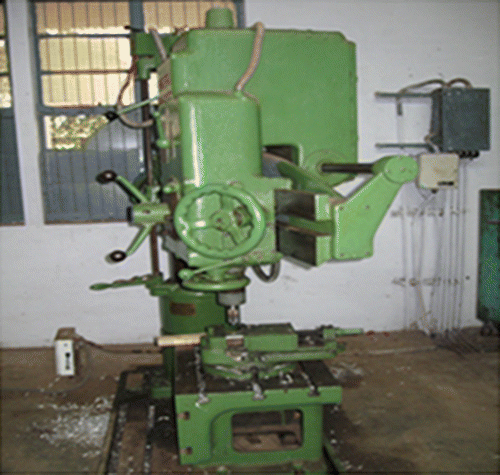
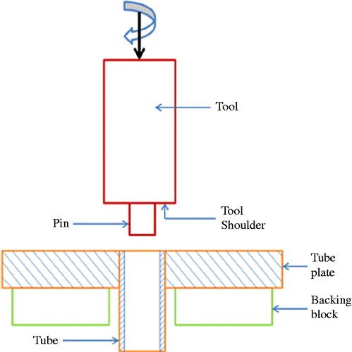
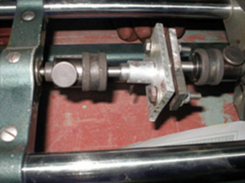
FWTPET process is capable of producing robust weld joints with enhanced metallurgical and mechanical properties. The FWTPET machine developed in-house is shown in Figure . The external tool consists of a shoulder and pin (Figure ). The tube to be welded was cleaned, and holes or slots were made along the faying surface of the tube. A suitable hole was drilled in a plate, and the tube was fitted and assembled in the FWTPET machine table.
The FWTPET machine consists of a tool holder, spindle, table and a supporting structure. The tool was lowered while in rotation, and heat was generated on account of friction when the shoulder touches the plate. The temperature generated in this process was approximately in the range of 0.6–0.7 times the melting point of the material. At this temperature, the plasticised metal flows towards the centre of the tool axis, and further metal flow was restricted by the cylindrical pin. Thereby pressure was developed at the interface between the tube and the plate. Thus, metallurgical bonding takes place between the tube and the plate. The temperature distribution in the plate is not uniform, and it results in the formation of fine-grained structure near the interface, which is flanked by a coarse-grained structure. Both the tube and the plate used in this study were made of commercially pure aluminium, and their chemical composition is given in Table .
Table 1 Chemical composition of parent metal.
Commercially pure rolled aluminium plates of 6 mm thickness were cut into the required size (50 mm × 70 mm) using a power hacksaw, and suitable external diameter tubes were cut into the required size. Then, suitable diameter holes according to the tube diameter were drilled in the centre of the plates (Senthilkumaran et al. Citation2010c). The use of backing block in the FWTPET process leads to a defect-free weld joint, less distortion and higher strength (Senthilkumaran et al. Citation2010a). The assembled work piece was fixed on the machine table with the fixtures, and the tool was fixed to the spindle. Tools made of tool steel were used to fabricate FWTPET joints in this study, and the chemical composition of the tool material is shown in Table . The assembly of the work piece was clamped on the machine table, and the tool was fixed to the spindle of the machine.
Table 2 Chemical composition of tool materials.
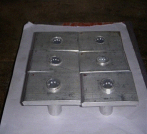
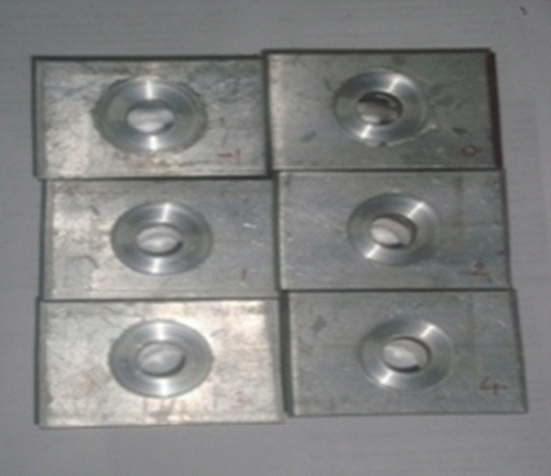
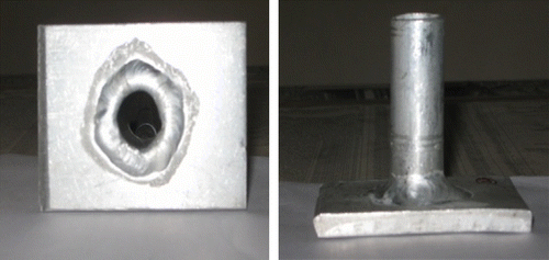
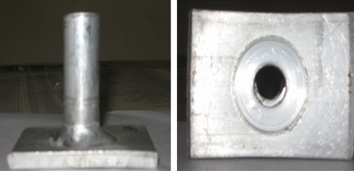
Figures and show the friction welded joint before and after performing the friction-welding process, respectively. Joints thus prepared were subjected to tensile test using a tensometer. Figure shows the tensile test specimen fixed in the tensometer.
2.2 Macrostructural studies
After the completion of welding, the tube-to-tube plate joints were sliced for macrostructural studies, and the rough scratches on the surfaces were removed using a belt grinder. The fine scratches were removed using emery sheet of different grades, and further polishing were done using alumina and diamond paste using a disc polishing machine. This was followed by etching the macrostructures using Tucker's reagent (composition: 4.5 ml HNO3, 2.5 ml H2O, 1.5 ml HCl, 1.5 ml HF). Then, the sample was washed, dried and observed under a macroscope.
2.3 Microstructural studies
The microstructural aspects of the friction-welded joints were studied through an optical microscope and the integrity of joints was analysed through the micrographs of the weld zone. Keller etchant was used for microstructure studies (composition: 2 ml HF, 3 ml HCl, 5 ml HNO3, 190 ml distilled water).
2.4 Gas tungsten arc welding
Gas tungsten arc welding or TIG welding is an arc welding process that uses an arc between the electrode (non-consumable) and the work pieces. Shielding gas is used in this process and can be performed with or without addition of filler metal. In this study, circumferential TIG welding was performed at different condition, as shown in Table and TIG parameters are shown in Table
Table 3 Different conditions for TIG welding.
Table 4 TIG welding parameters.
Commercially pure rolled aluminium plates of 6 mm thickness were cut into the required size (50 mm × 70 mm) using a power hacksaw, and 19 mm external diameter tubes were cut into required sizes. Then, 19 mm diameter holes were drilled in the centre of the plates. Then, circumferential TIG welding was carried over the tube-to-tube plate welded joint. Samples were joined with various combination such as carrying out TIG welding after friction welding and vice versa. Figures and show TIG and combination of FWTPET+TIG after welding, respectively.
2.5 Evaluation of pitting corrosion resistance
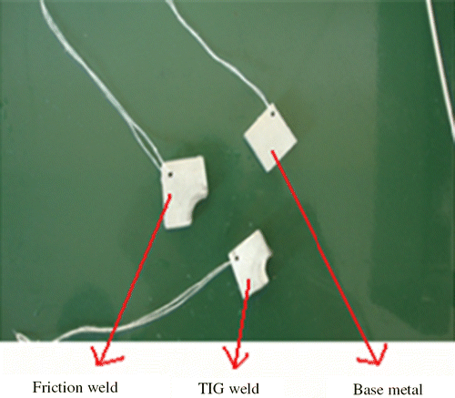
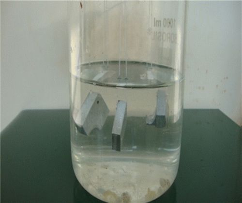
Immersion corrosion test was used to study the corrosion behaviour of AA2024 in sodium chloride solution (Obispo et al. Citation2000). The pitting corrosion test was carried out according to ASTM G110-92. Immersion tests were performed on 1 μm diamond polished surfaces. The longitudinal cross sections of welds were immersed in the solution for 24 h. Before immersion in the test solution, each specimen was immersed in etching solution for 1 min. The etching solution consists of Poltroon 20 ml (12 ml HCl, 6 ml HNO3, 1 ml HF, 1 ml H2O)+10 ml HNO3+16 ml chromic acid (3 g chromic acid, 13 ml H2O). The specimens were then rinsed in the reagent water and again in distilled water and dried in moving air, and then they were immersed in the test solution. The test solution consists of 57 g of sodium chloride (NaCl) and 10 ml of hydrogen peroxide (H2O2), H2O2 is diluted to 1 L with reagent water. The volume of the test solution per exposure area is 5 ml/cm2. The exposure time was 6–24 h. After exposure, each specimen was rinsed with reagent water and allowed to dry. Examination of specimens was done according to the ASTM G110-92 specification. The depth of intergranular and pitting corrosion is observed on transverse cross sections by optical microscopy. Figures and show the arrangement of immersion corrosion of test samples.
3. Environmental friendlier aspects
The eco-friendly aspects associated with FWTPET process are presented as follows.
3.1 Mass of the material
3.2 Material lost during machining
3.3 Mass of the filler metal added during welding
3.4 Percentage waste
3.5 Percentage of mass utilisation
3.6 Labour cost
3.7 Consumables charges
3.8 Power charges
4. Results and discussion
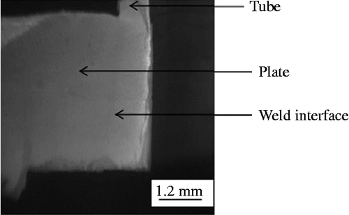
On the basis of tensile strength observation, it was found that a maximum strength occurred in FWTPET welds compared with the bottom side TIG welds, top side friction welds and both sides TIG welds. It was observed that friction welding possesses maximum tensile strength compared with other welding conditions because of better bonding that occurs between the tube and the tube plate. When more quantity of plate material which is in plastic condition is forced through small holes, the tube surfaces surrounding the holes may reach plastic condition. Hence, better metallurgical bond is achieved in the case of small holes. Hence, a maximum tensile strength that has been achieved by the FWTPET process mainly depends on weld conditions. Figures show the macrostructural observations pertaining to different welding processes. On the basis of the macrostructural observation, it is found that the FWTPET process, compared with top friction welding and bottom TIG welding and both side TIG welding, is a defect-free welding process, whereas to remaining welding methods are susceptible to defective welds because of improper bond between the tube and the tube plate. Fine grain structure was observed in the weld zone interface as shown in Figure (a). In solid-state welding, especially in friction welding, due to severe deformation, the refined grain structure is observed at the weld zone, which resulted in improved properties. However, the fine grain structure is not observed at the weld zone interface in the TIG welding process as shown in Figure (b). Therefore, the properties are not improved in the TIG process compared with FWTPET process. The consolidated aspects of TIG, FWTPET and the combined process (TIG+FWTPET) are presented in Table . The eco-friendly aspects of TIG and FWTPET are compared and presented in Table .
Figure 11 Macrostructure of FWTPET+TIG welding: (a) bottom side FWTPET macrostructure and (b) top side TIG welding macrostructure.
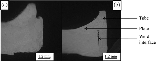
Figure 12 Macrostructure of TIG welding: (a) bottom side TIG welding macrostructure and (b) top side TIG welding macrostructure.
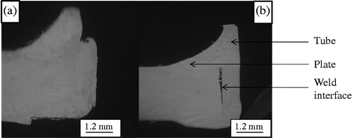
Figure 13 Microstructure of FWTPET+TIG welding: (a) microstructure of FWTPET welding and (b) microstructure of TIG welding.
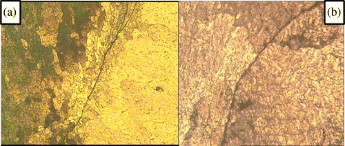
Table 5 Comparison of various aspects of TIG, FWTPET and (TIG+FWTPET).
Table 6 Comparison of eco-friendly aspects of TIG and FWTPET processes.
5. Conclusions
Competitiveness has forced the manufacturing organisations to recognise eco-friendliness as a vital concept for survival. The eco-friendly aspects associated with machining gain importance. In this context, this article presents the eco-friendly aspects associated with FWTPET process. The unique features of this process are capable of producing leak proof joints with lesser energy consumption. The comparative aspects of FWTPET with conventional TIG process from the perspective of eco-friendliness have been exemplified.
Acknowledgements
The authors wish to express their sincere thanks to the Ministry of Human Resource Development (MHRD), Government of India, for the financial support to carry out this investigation.
Notes
References
- Brien , R.L.O. 1991 . Welding handbook , 8th ed. , vol. 2 , New York : American Welding Society .
- Hadj Taieb , A. , Msahli , S. and Sakli , F. 2010 . Design concept for an ecological relaxing textile product using solar energy . International Journal of Sustainable Engineering , 3 ( 2 ) : 133 – 142 .
- Kalyanmoy , D. 1996 . Optimizations for engineering design – algorithm and examples , 290 – 333 . New Delhi : Prentice Hall of India .
- Muthukumaran, S., 2008. A process for friction welding of tube to tube sheet or a plate by adopting an external tool. Indian patent application no. 189/KOL/06 (filed on 07-03-2006), patent no. 217446 (Granted on 26-03-2008), IPR India
- Muthukumaran , S. 2010 . “ Friction welding of tube to tube plate using an external tool – a study ” . In Proceedings of International Welding Symposium 2010 241 – 245 . Indian Welding Society
- Obispo , H.M. 2000 . Copper deposition during the corrosion of aluminum alloy 2024 in sodium chloride solutions . Journal of Materials Science , 35 : 3479 – 3495 .
- Senthilkumaran , S. , Muthukumaran , S. and Vinodh , S. 2010a . Experimental and numerical investigation of weld joints produced by friction welding of tube to tube plate using an external tool . International Journal of Engineering, Science and Technology , 2 : 109 – 117 .
- Senthilkumaran , S. , Muthukumaran , S. and Vinodh , S. 2010b . Optimization of friction welding of tube to tube plate using an external tool . Structural and Multidisciplinary Optimization , 42 : 449 – 457 .
- Senthilkumaran , S. , Muthukumaran , S. and Chandrasekhar Reddy , C. 2010c . Effect of tube preparations on joint strength Friction welding of tube to tube plate using an external tool process . Experimental Techniques , DOI: 10.1111/j.1747-1567.2010.00700.x
- Senthilkumaran , S. , Muthukumaran , S. and Vinodh , S. 2011 . Optimization of friction welding of tube to tube plate using an external tool by hybrid approach . Journal of Alloys and Compounds , 509 : 2758 – 2769 .
