Abstract
The use of flowing water in embedded pipes to harvest heat energy from asphalt pavements and thereby reducing its temperature and the urban heat island effect has been proposed. A successful use of such an approach would require a complete understanding of the effect and the interaction of various mechanisms such as conduction, convection and radiation and factors such as solar radiation, diameter of pipe and rate of flow. A large-scale experiment was conducted to understand such effects, and numerical modelling was conducted for prediction of temperature. The experiment was modelled using finite element method, and a good match was obtained between predicted and experimentally obtained results. Effects of pipe diameter and flow rate were also analysed. This model could be used in future for selection of appropriate levels of critical variables and hence successful implementation of this concept to sustainable pavements.
Keywords:
Introduction
As pavements are an integral part of our society, developing sustainable pavements and integrating them into our urban landscape for energy utilisation is an important long-term goal. The concept of extracting solar energy from asphalt pavements has been proposed (Loomans et al. Citation2003, Hasebe et al. Citation2006, Mallick et al. Citation2008, Citation2009a, Citation2009b). The immediate motivation for extraction of energy from pavements is to reduce pavement surface temperature thereby reducing rutting. This is because the plastic strain (that leads to rutting) is primarily dependent on the temperature of the pavement (which has a significant effect on the stiffness of the mix), as indicated below (NCHRP Citation2002):
Currently, prevention of rutting is an expensive process, involving the use of very expensive polymers, which are produced through a very energy-intensive process; rehabilitation of pavements with rutting is also a very expensive and energy-intensive process, involving milling and paving. Furthermore, such rutting can occur in the rehabilitated pavement as well, leading to an endless cycle of rehabilitation and failure.
As pavements tend to absorb solar energy more than the ground, it also contributes to urban heat island effect. Therefore, reduction in pavement temperature may also aid in reducing urban heat island effects (Mallick et al. Citation2009a, Citation2009b, CitationChen et al. 2009). The basis for this assumption is that the amount of heat energy that is radiated back from the pavement is dependent on the difference of temperature between the pavement surface and the air, and is given as follows:
The extracted energy can be used for various applications in buildings and process plants, such as process heat, power and refrigeration/air conditioning systems.
The preliminary approach in this concept has been to flow fluid in pipes below the pavement surface. The fluid will rise in temperature, as it flows through the pavement, and the hot fluid can be used for different applications. In the process, the temperature of the pavement will be maintained at a lower than the normal temperature, and hence less heat will be radiated back into the air. As a consequence, the air quality will improve, the energy use of buildings adjacent to such pavements will be reduced and the pavement will be less susceptible to high temperature then reducing rutting.
Developing an engineering system based on this concept requires an understanding of the relationship between a host of different parameters including the incident solar radiation, temperature of inlet water and rate of flow of water and the pipe dimensions and spacing. All these factors significantly affect the heat energy that can be harvested which alters the surface temperature. Understanding the heat transfer characteristics between the pavement and the pipes carrying the fluid under different solar radiation and cooling load is essential for the advancement of this technology. All of the current literature that is available on this subject is related to experimental work and modelling for the evaluation of structural stress–strain in pavements. No literature is available on a comprehensive modelling and simulation of the heat transfer process between the incident solar radiation and the flowing fluid in embedded pipes. The authors of this paper have previously conducted modelling and validation using small-scale experiments. The study reported in this paper was conducted to develop models, simulate the process of heat transfer and validate the models with large-scale experiments. The validated models could then be utilised to simulate different types of solar radiation that are expected in different seasons and in the different parts of the world, so that an accurate evaluation of the heat transfer process and hence the energy harvesting process could be made.
Because of the complex relationship of heat transfer between conduction, convection and radiation and the multitude of piping dimensions and layout possible, it is imperative that optimisation will require a numerical approach. However, the development and adoption of a proper numerical model requires the validation through a large-scale experiment. Such a large-scale experiment was carried out under natural solar radiation in Worcester, MA, USA (42°N, 71°W).
Objective
The objectives of this study were to develop a finite element (FE) model (COMSOL Multiphysics Citation2009) of a setup of flowing water in pipe embedded in an asphalt pavement, develop an experimental setup, conduct experiments, compare the results of experiments with those from simulations run with the model and evaluate the effect of key parameters. The steps consisted of the following:
| 1. | build and instrument a pavement slab with copper pipe, | ||||
| 2. | flow water through the pipe and collect environmental and temperature data, | ||||
| 3. | develop a FE model, | ||||
| 4. | input initial conditions and collected environmental data, | ||||
| 5. | run simulations, | ||||
| 6. | compare the results obtained from experiments with those from FE simulations and | ||||
| 7. | evaluate the effect of key parameters. | ||||
Experimental and modelling work
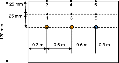
A slab (Figure (a)) was prepared with 125 mm thick HMA (dense graded hot mix asphalt typically used for surface) layer, with a frame of copper tube (Figure (b)) embedded inside. The copper tubes were provided for pumping water (heat exchanger) through the slab. Thermocouples (Figure (c)) were inserted along the depth and at various points in the slabs, including points in line with the copper tube locations, and inlet and outlet points of the water flowing through the copper tubes (Figure ). A copper tube frame with multiple tubes along the width and one tube along the length was placed approximately 38 mm below the surface during placement and compaction inside wood carts.
Figure 1 Slab with copper tube (a) experiment in progress, (b) compacted slab with pipes (without the top layer), (c) fixing of thermocouples on the compacted slab.
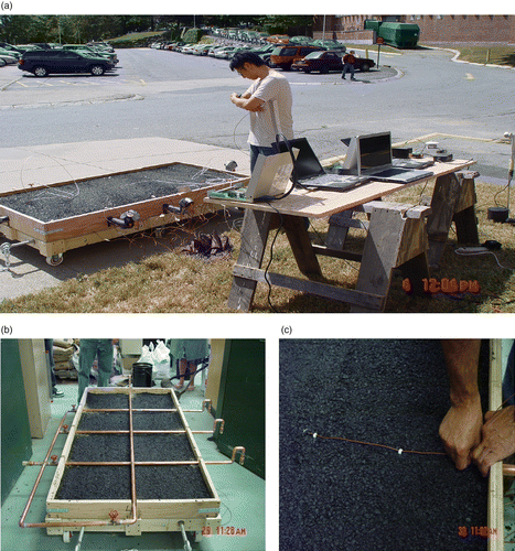
Figure 2 Copper tube frame inside slab and thermocouples on the slab (not to scale). Note: In this experiment, water was flown through only one of the three pipes – the one that is indicated by a blue filled circle.
Data acquisition system
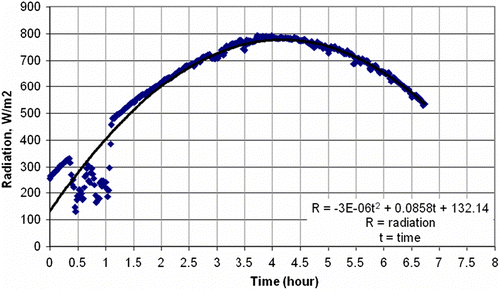
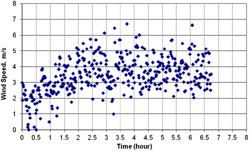
Wind speed and solar radiation were measured using an anemometer (Campbell Scientific, 014A-L) and a pyranometer (Kipp & Zonen/Campbell Scientific, CMP-3, Bohemia, NY, USA and Logan, Utah, USA), respectively. The solar radiation data were modelled with time, and the results are shown in Figure . The values ranged from approximately 255 to 800 W/m2. The data for the wind speed versus time are shown in Figure .
First, before any water was flown, the slab was kept under the sun for approximately 4 h, and temperatures at various depths at the centre of the slab were recorded. Next, water was pumped at 1, 2, 3 and 4 l/min, and temperature of the slab at the copper tube location as well as incoming and outgoing water was measured. The slab was allowed to heat up for 4.7 h followed by running water at increasing flow rates of 1 l/min at half an hour intervals.
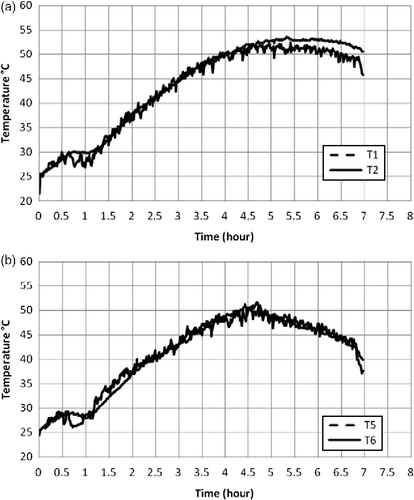
Temperature data were collected at several points in the slab (shown in Figure ), of which those at the surface and 25 mm below the surface are shown in Figure .
Modelling
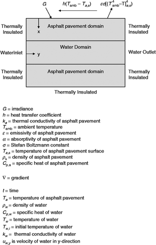
The heat transfer problem is a coupled conduction–convection–radiation problem with appropriate boundary conditions at the pavement–air and pavement–water interface. The problem is illustrated in Figure . The problem has two domains – the asphalt mix domain in which the transient conduction heat equation is solved and the water domain in which the convective terms play an important role. The mean water velocity was obtained from the conservation of mass. Appropriate values for boundary conditions were used. FE analysis was conducted using COMSOL (COMSOL Citation2009).
Boundary condition on the surface of asphalt pavement
Governing equation (asphalt domain)
Governing equation (water domain)
Boundary condition (interface between asphalt pavement and water)
Boundary condition (water inlet)
Boundary condition (water outlet)
Boundary condition of asphalt pavement below pipe:
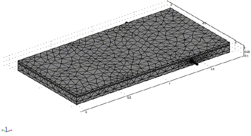
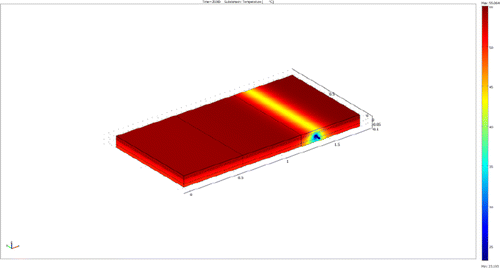
The experimental setup was modelled in finite element method (FEM) to determine the temperature at the different points. Even though three copper pipes were present in the slab, only one, through which water was flown, was modelled in the FE method. The reason for using one pipe was to allow running the models within a practical time limit with the available computational resources. Furthermore, with spacings used in the experiment, the effect of one pipe on another was not significant. A time-dependent solar radiation was used in the model. The details of model are shown in Figures and .
Results
The timing of the different events is shown in Table . The water was flown at varying flow rates to simulate a wide range of possible scenarios. The goal was to find the effect of flow rate on the temperature of the slab at various locations.
Table 1 Sequence of events.
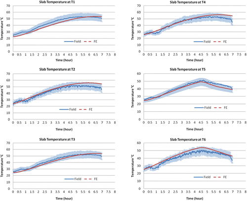
The temperature of all the thermocouples remained almost invariant for the first hour. This coincides with almost no change in incoming solar radiation for the first hour. The model assumes a polynomial profile for the first 1 h; therefore, predictions for the first hour are a bit off for the temperature in the slab. Between hours 1 and 4.7, the temperature profile shows an increase, reflecting the increasing solar radiation as the daylight increases. Because wind velocities were within a narrowly defined range, the temperature variation was not influenced by the wind speeds in the experiment. The numerical model was able to predict the temperature for all the thermocouples within the margin of error.
Because of the variation in solar radiation, it is important to take into consideration the temperature fluctuation due to the decrease in solar radiation after 4 h. By looking at thermocouples 1 and 2 (which can be treated as the part of the slab in which the effect of flowing water did not reach), it is apparent that the temperature went up for 30 min followed by almost a constant value for the next 3 h. This indicates that the asphalt pavement is a good energy storage system.
Once the water started to flow in the pipe as indicated in Figure , immediate drop in temperature was observed in T5 and T6 (Figure (b)). Overall in the next 3 h the slope was steeper for T5 than for T6 because it was 25 mm above the water pipe compared with T6 which was 50 mm above. Therefore, the flow of water was able to cool 50 mm around the pipe. However, none of the effect of the flowing water was felt in thermocouples 1–4 that were located over 0.6 m to the left. Another observation from the experiment was that it was not possible to detect the increasing effect of flow rate for every successive hour from 1 to 4 l/min over half-hour time steps. The surface temperature (as measured by T6) was found to decrease significantly with the flowing of water (approximately 10°C, when compared with T4). This observation is significant, because this indicates that the potential of reducing the amount of heat energy that is radiated back from the surface, with the help of the proposed system, is real.
The modelling was able to predict the temperature distribution of all the thermocouples as a function of time. It should be noted that the temperature distribution predicted at the surface (T2, T4 and T6) tended to be consistently higher than the measured temperatures, although the overprediction was within the margin of error (Figure ). Part of the error is in the inaccuracy of the thermocouple placement at the surface. However, the results indicate that it was possible to incorporate the variable boundary conditions and predict the temperature distribution before the water was flown and after the water was flown. The next step was to determine the height and depth around the pipe in which cooling could be achieved as a function of the flow rate and pipe diameter.
Figure 9 Plots of temperature versus time for field (experimental) and FE (simulation) data (shaded area denotes 10% error bars around field values).
Effect of pipe diameter and flow rate
FE simulations were performed to determine the temperature distribution within the slab due to the effect of pipe diameters (6.4, 12.5, 19 and 25 mm) and flow rates (1 l, 3 l, 5 l and 7 l/min). The slab dimension and solar radiation are indicated in Figures and .
The horizontal temperature profiles were taken at the water exit location after 5 h and 20 min and from the centreline of pipe/water (x = 1.3176 m) to the horizontal distance in which pavement temperature becomes steady (x = 1.7 m). The vertical temperature profiles were taken at water exit location when time = 5 h and 20 min and from the centreline of pipe/water (z = − 0.0635 m) to the surface of pavement (0 m).
Figure (a–d) shows the temperature distribution from the surface to the bottom layer of a slab with a 6.4, 12.5, 19 and 25 mm pipe and 1 l/min flow rate placed at 38 mm below surface.
Figure 10 (a) Temperature distribution (6.4 mm diameter pipe with 1 l/min). (b) Temperature distribution (12.5 mm diameter pipe with 1 l/min). (c) Temperature distribution (19 mm diameter pipe with 1 l/min). (d) Temperature distribution (25 mm diameter pipe with 1 l/min).
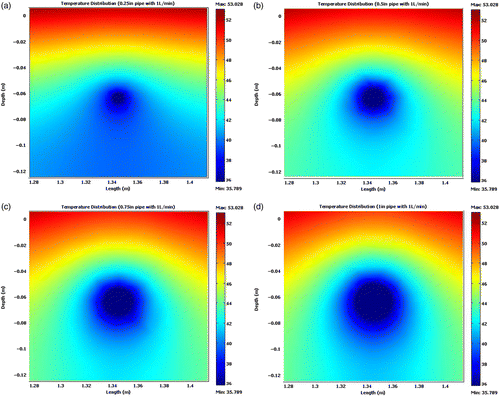
As can be seen from the contour plots, the temperature distribution within the slab is axi-symmetric. However, around the pipe the temperature distribution is uniform for a small diameter. This diameter is larger for the larger diameter pipe. This is the region in which the convection effects from the flowing water are predominant. Beyond that region the effects of conduction are apparent as one gets successive bands of increasing temperature profiles. The shape of these profiles varies as seen in the figures, with higher diameter pipes having more concave profile because of the varying curvature effects of the pipe. Clearly, the greater the diameter, the further is the effect of the flow in the slab.
Figure (d) clearly shows that the temperature variation around the large pipe is rapidly increased and lower temperature zone is created around the pipe; moreover, the slab temperature from the surface to the elevation of pipe is also reduced approximately by 5°C when comparing 6.4 and 25 mm diameter pipes.
Figure (a) shows different pipe diameters (6.4, 12.5, 19 and 25 mm) with 1 l/min flow rate (horizontal distance). First, a uniform water temperature can be seen from the centreline to the edge of pipe followed by increasing temperature in the pavement. The modelling was done with a uniform mean temperature of the fluid within the pipe. The temperature of the water was lowest in the highest diameter pipe. It also shows that when the pipe diameter increases, the steeper temperature variation occurs from pipe–water to adjacent pavement, which means that the larger pipe diameter results in lower water temperature and a higher rate of lowering of the pavement temperature.
Figure 11 (a) Different pipe diameters with 1 l/min flow rate (horizontal distance). (b) 0.75″ pipe diameter with different flow rates (horizontal distance).
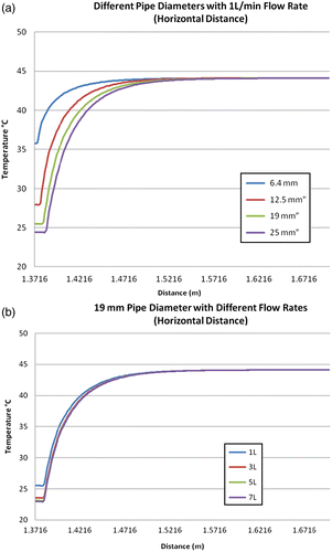
Figure (b) shows the flow rate increase from 1 to 7 l/min (horizontal distance). The adjacent pavement temperature slightly decreases as the flow rate increases. It also shows that when the flow rate increases, only a slight temperature variation occurs from pipe–water to adjacent pavement, which means that the increases in flow rate do not have as great an impact on the reduction in temperature as the pipe diameter.
Figure (a) shows the different (6.4, 12.5, 19 and 25 mm) pipe diameters with 1 l/min flow rate (vertical distance). The uniform water temperature can be seen from the centreline of pipe–water (z = − 0.0635 m) to the edge of pipe, and the temperature starts to increase towards the pavement surface. It shows that when the pipe diameter increases, the steeper temperature variation occurs from pipe–water to pavement surface, which means that the larger pipe diameter (location) results in lower water temperature and a higher rate of cooling of the pavement surface.
Figure 12 (a) Different pipe diameters with 1 l/min flow rate (vertical distance). (b) 0.75″ pipe diameter with different flow rates (vertical distance).
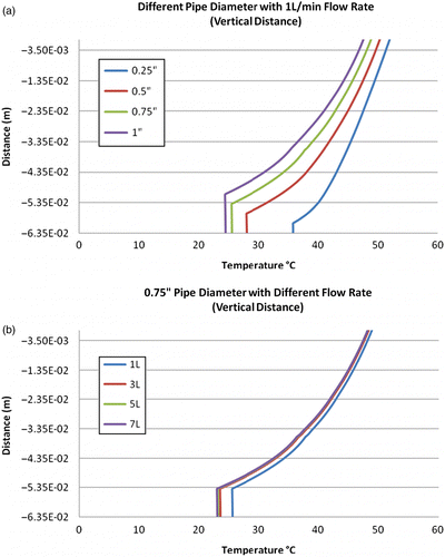
Figure (b) shows the effect of increase in flow rate from 1 to 7 l/min (vertical distance). The pavement surface temperature decreases slightly as flow rate increases. It also shows that when the flow rate increases, the slight temperature variation occurs from pipe–water to pavement surface, which also means that the increase in flow rate does not have as much impact on reducing temperature as increasing pipe diameters.
Discussion of results
Experimental and calculated temperature data from pipe with flowing water in asphalt pavement were compared. The experimental data were collected from the slabs subjected to solar radiation. The calculated temperatures were obtained from FE models and simulations. The calculated results show good agreement with the experimental results. The FE models were used to evaluate the effect of different parameters on the proposed system.
The harvesting of heat energy by transferring the solar radiation energy from the pavements to a fluid has many practical implications. First, the transferred energy can be utilised for useful purpose. Second, the transfer of energy will result in a reduction in the temperature of the pavement, thus enhancing its life. Third, if the temperature of the pavement is reduced by harvesting of heat energy, then the amount of heat that is emitted back from the pavement (which contributes to the urban heat island effect) could also be reduced. However, the effective use of this concept depends on a number of interdependent factors, the effects of which need to be understood properly. Such a proper understanding is critical for the construction of a control system that could regulate the flow of fluid through the pipes in the most optimum way so as to extract the maximum amount of heat energy from the pavements. The ultimate aim is to implement this concept with the help of a robust feedback controlled system in which the controller will be able to switch on the energy harvesting system when appropriate solar radiation/temperature/wind speed exists, and switch it off when such extraction is not feasible.
A key element of this control system is the input temperatures from the pavement system and the surrounding air. It is important to determine the critical input temperature that should prompt the controller to start the fluid flow and control it at a given flow rate. Various transient simulations need to be performed using different flow rates, pipe spacing, pipe diameters and finally boundary conditions (radiation–convection). This would allow one to create a matrix of transient temperature distribution of the pavement–pipe network and to determine the proper number of inputs to the controller.
Furthermore, scenario analysis of different thermal fluctuations will include long-term climate patterns as well as sudden changes in weather. The critical combination of temperature sensors in the pavement, air temperature sensor, wind speed and solar radiation that are required as input to the controller needs to be determined. Some of the questions that need to be answered are whether placement of temperature sensors in the road requires a critical set of locations, how important are the air temperature and wind speed in the damping system and whether they are required as input to the controller, does solar radiation override most of the factors? Can it be used as a single contributor for rapid change scenarios (e.g. fall of solar radiation due to cloud cover allows us to keep the control system off) and what are the required flow rates in the pumping system for the different scenarios? Without proper answers to these questions, the user runs the risk of investing a large amount of time, energy and effort in building a system that might not provide the expected harvesting of energy. And any such failure could actually prevent people from trying this concept in the future.
This is the first time that a numerical model of this concept has been developed and validated against a large-scale experiment. The validated model presented in this paper would allow the users to answer the above questions. It is recommended that the model be used for the simulation of different conditions and obtaining answers to the above questions. The use of this model could help in more widespread adoption and hence a better use of this technology for obtaining sustainable pavements.
Major conclusions
The major conclusions from this study can be listed as follows:
| 1. | It is possible to successfully model the conductive–convection–radiation problem of heat transfer through fluids in a pavement. | ||||
| 2. | The flowing of a cooler fluid through pipes in pavements is successful in both extracting heat energy and lowering the temperature of the pavement to a significant extent. | ||||
| 3. | The effect of heat extraction is limited within a zone around the pipe – whose extent depends on the pipe diameter and the flow rate. | ||||
| 4. | The effect of pipe diameter is more significant than the effect of flow rate. | ||||
Implementation of the proposed system
The implementation of the proposed system of harvesting heat energy requires three major steps. First, one needs to determine the amount of heat energy that is available at a specific depth in a pavement at a specific location, and thereby justify (or not) the amount of recourses that need to be spent. This can be accomplished using a user friendly macro-based spreadsheet that has been published by the authors (Mallick et al. Citation2011). The second step is to design an optimum system that could harvest the maximum amount of heat energy. The model presented in this paper could be utilised to accomplish the design. Note that copper pipes have been used in this study. It is very probable that non-metallic pipes will be used in actual implementation. The selection of a proper pipe will be possible with the help of the proposed model and simulation. The last step is to ensure the structural integrity of the system by conducting stress–strain analysis in response to loading and temperature fluctuations. The risk of selection of an improper system will be reduction in the structural life of the pavement.
Once implemented successfully, the extracted heat energy from the proposed system can be used for process heating, feedwater for other applications or as a heat exchanger fluid for heating cycle. The water at high temperature could be stored in insulated chambers for hydronic heating of buildings during heating seasons. Many industrial processes need elevated temperatures. For example, cleaning/degreasing/rinsing of metal parts is more effective at higher temperatures. Many food processing operations are done at elevated temperatures. The temperature of the fluid passing through a hot pavement could be low for pasteurisation, but might be good for other food processing. Anaerobic methane generation needs elevated temperature, greater than 30°C, to work (commonly used to ‘treat’ wastewater high in organics). So the hot water produced could be directed to internal or external heat exchangers in anaerobic methane generators. Also, a heat exchanger could be used to use the water to preheat domestic hot water in buildings – for example hot water for sinks and showers. The temperature of the water coming into the building (more than likely at a temperature significantly below room temperature) could be raised before the water enters the water heater. It would save energy needed for the water heater (electricity, natural gas, oil). Lastly, in many areas the hot fluid (e.g. glycol based with a low-freezing point) could be stored and utilised for deicing pavements during winter months.
Acknowledgements
Funding for this study was provided by Massachusetts Technology Collaborative, Inc. and Faculty Advancement Research (FAR) Award from Worcester Polytechnic Institute (WPI). The authors are deeply grateful to Gerard Moulzolf of American Engineering Testing, Inc. for providing the most valuable information and to Mr Ron Tardiff of Aggregate Industries and Mr Jeff Carlstrom of New Ulm Quartzite Quarries for providing the samples. Finally, this study would not have been possible without the laboratory and shop help from Ms Laura Rockett, Mr Don Pellegrino and Mr Dean Daigneault of the Civil and Environmental Engineering Department at WPI. The authors are also grateful to Mr Michael Hulen of Novotech, Inc. Mr Phillip Ingersoll-Mahoney and Mr Dennis Rice of Alternatives Unlimited, Inc.
Notes
References
- Chen , B.-L. , Sankha , B. and Mallick , R.B. 2009 . A laboratory study on reduction of the heat island effect of asphalt pavements . Journal of the Association of Asphalt Paving Technologists , 78 : 209 – 248 .
- COMSOL, 2009. Heat transfer module user's guide. COMSOL Multiphysics 3.2., COMSOL Inc., Bushington, MA, USA
- Hasebe , M. , Kamikawa , Y. and Meiarashi , S. 2006 . “ Thermoelectric generators using solar thermal energy in heated road pavement ” . In Proceedings of ICT '06. 25th international conference on thermoelectrics 697 – 700 .
- Loomans , M. 2003 . “ Design tool for the thermal energy potential of asphalt pavements ” . In 8th international IBPSA conference August 11–14, Eindhoven, The Netherlands
- Mallick , R.B. 2008 . “ Capturing solar energy from asphalt pavements ” . In International symposium on Asphalt Pavements and Environment, International Society for Asphalt Pavements Zurich, Switzerland
- Mallick , R.B. , Chen , B.-L. and Bhowmick , S. 2009a . “ Reduction of urban heat island effect through harvest of heat energy from asphalt pavements ” . In Presented and published in the proceedings of the 2nd international conference on Countermeasures to Urban Heat Islands Effect Berkeley, CA, September
- Mallick , R.B. , Chen , B.-L. and Bhowmick , S. 2009b . Harvesting energy from asphalt pavements and reducing the heat island effect . International Journal of Sustainable Engineering , 2 ( 3 ) : 248 – 214 .
- Mallick , R. 2011 . Evaluation of the potential of harvesting heat energy from asphalt pavements . International Journal of Sustainable Engineering, , 4 (2) : 164 – 171 .
- National Cooperative Highway Research Program (NCHRP) . 2002 . Design guide: Mechanistic-empirical design of new & rehabilitated pavement structures , Washington, DC : NCHRP .
